1. Introduction
The verification methods presented here aim at determining the collapse load of a hemispherical masonry dome subjected to an axisymmetric load on the crown. The same method is considered for the reinforcement of historical or overloaded domical structures by means of FRP strips.
The case study is a physical model with the same characteristics (about 2.2 m in diameter, 0.12 m thick with 0.20 m wide oculus on the top) and mechanical properties as detailed in [
1]. It was built and tested under a vertical load and in case of reinforcement until collapse in the laboratory of the IUAV in Venice [
2]. From these few mechanical tests, a series of numerical and analytical computations [
1,
3,
4,
5,
6,
7,
8,
9] have been performed to find the ultimate collapse load and the position of plastic hinges.
The method finds its significance and utility for both research and professional works. Indeed, all of the methods that were found in the literature are, in the abovementioned cases, expensive in terms of time and computational capacity or neglect important features of masonry [
10], while the proposal presented here is quick, it can be implemented in every simple finite-elements (FE) software and considers masonry tensile resistance and orthotropy. The method has been validated by the authors in precedent works on arches [
11] and domes [
12].
In the paragraphs below, the reader may find brief information about two ways of modelling for nonlinear analysis (involving brittle and ductile elements) and the consequent results. Finally, the second method of elastic perfectly ductile elements is applied to simulate the behaviour of FRP strips and demonstrate their efficacy.
2. Modelling Methods
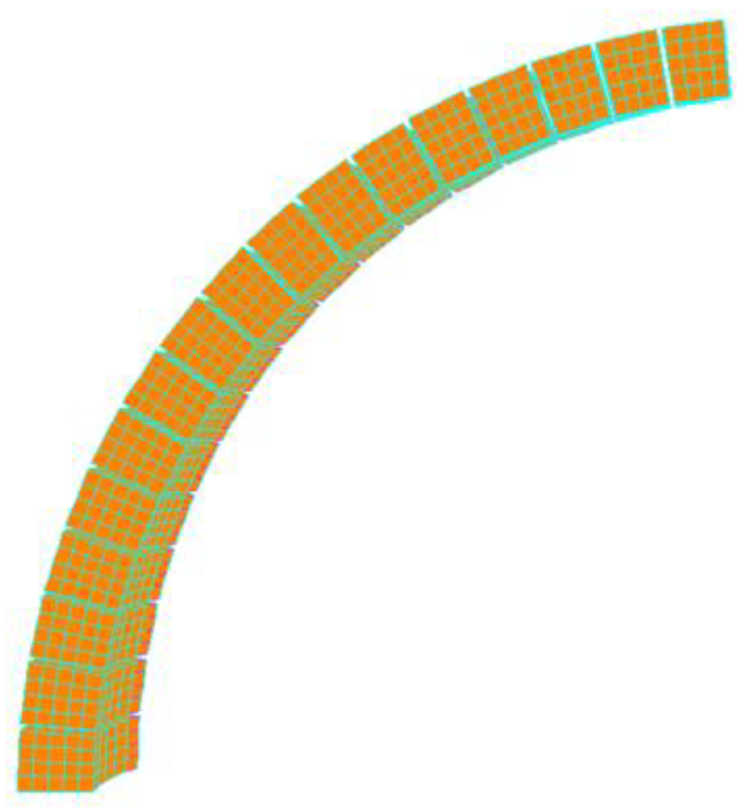
The modelling and the nonlinear analysis have been performed in a commercial FE environment. A meridian slice of a hemispherical dome (the reader may find an example in
Figure 1) was used to speed up computations and, finally, the results were made commensurate to the whole dome using simple math.
To replicate the axisymmetric load applied to the physical model, a point load on the upper crown, close to the oculus was set by imposing a unit displacement.
Considering that failures in such structures often occur at the mortar joints and not in the clay bricks, these have been modelled as elastic hexahedral elements (3D) and are never expected to fail. As masonry domes show material and geometrical nonlinearities, these have been lumped in the mortar joints, modelled by 1D finite elements—already implemented in the software used, namely Point Contacts (PCs) and Cutoff Bars (CoBs). The next two paragraphs detail and explain the choice.
2.1. Elastic Perfectly Brittle Joints: Point Contact
In the first way of modelling, joint nonlinearity is set by elastic perfectly brittle PCs, which are categorised as 1D “beam elements” and used under Heyman’s hypotheses of no-tension materials and the small displacements hypothesis. They are set to work in compression only. No sliding is accounted for.
Results
The results of such modelling are shown in the sensitivity analysis in
Figure 1. It compares the collapse loads resulting from small changes in the tensile resistance assigned to horizontal joints only (f
T,h), while vertical joints were set to be no-tension. The curves show some mutual differences in their behaviour in the first steps of the simulation (rectangle a in
Figure 2), with a progressive loss of structural stiffness and the development of plastic hinges. While in the steps near the end, they tend toward the asymptote value given by the lower-bound Limit Analysis (LA) found in [
9] (rectangle b in
Figure 2).
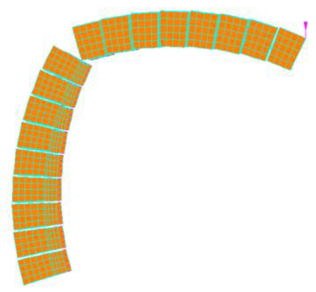
In spite of a largely conservative collapse load value, such an analysis gives an accurate position of the plastic hinge (at 45° from the vertical axis), visible in the deformed shape in
Figure 3.
2.2. Elastic Perfectly Ductile Joints: Cutoff Bars
The second type of model sees nonlinear joints configured as elastic perfectly ductile truss elements (1D) [
11] with predefined tensile and compressive strengths, namely CoBs. The cutoff values for tension and compression are suitably tuned to simulate masonry orthotropy.
Additionally, a rigid base larger than that of the point load (a scheme in
Figure 4a) is added to simulate the load distribution of a real architectural element on the crown of the dome. Then, to prevent out-of-plane sliding, shear resistance has been provided by a complex joint construction involving rigid beams, CoBs and shear trusses (the reader may refer to
Figure 4b for more clarity). The failure of this structure is explained by the formation of a plastic hinge. For the sake of brevity, no more information will be reported here.
Results
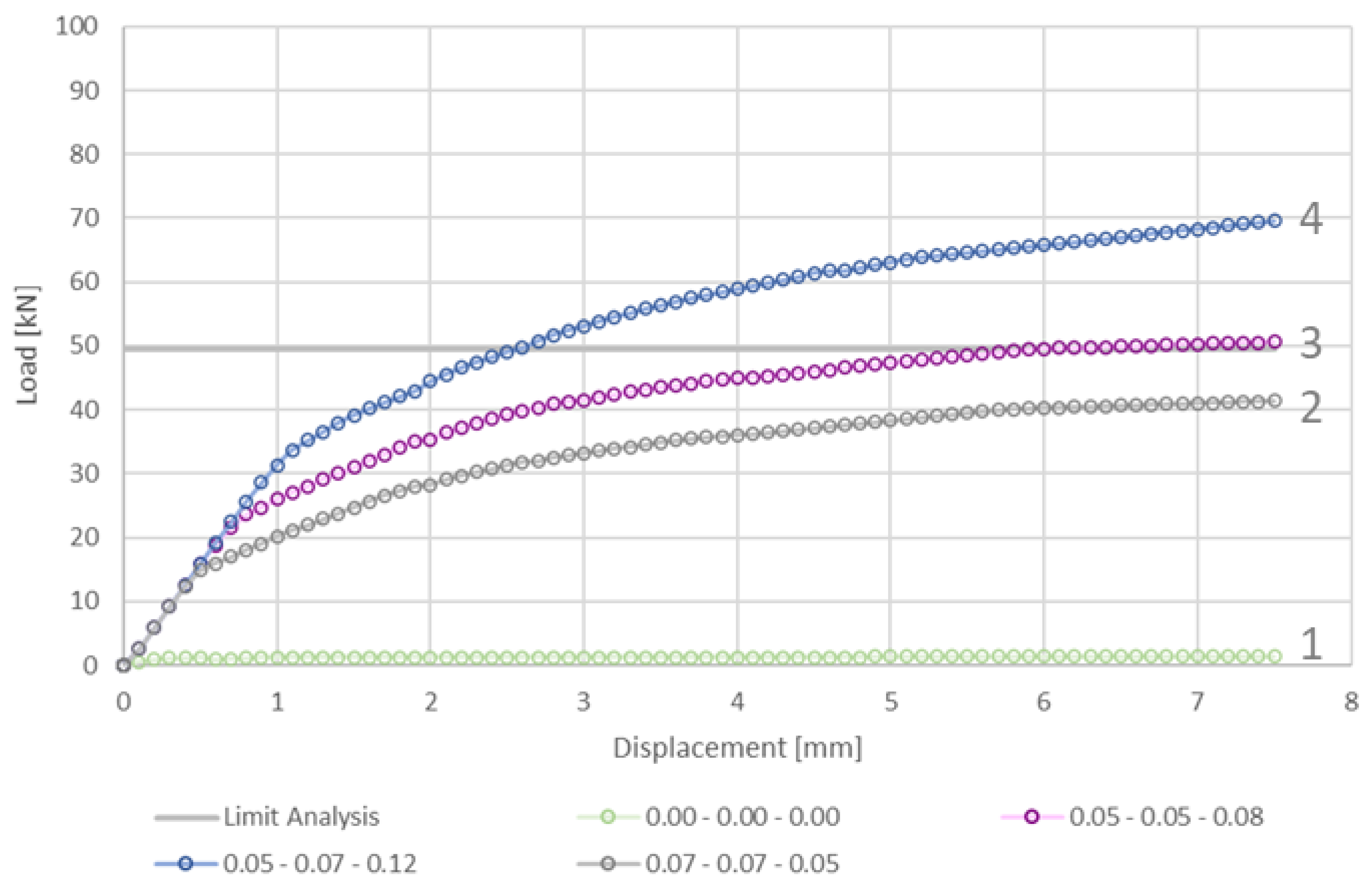
The results of the second model are shown in the essential sensitivity analysis of
Figure 5. Each curve results from tuning the tensile resistance values along horizontal (f
T,paralel) and vertical (f
T,meridian) directions. The values, collected in
Table 1, are always multiplied by the influence area of the joint, which depend on the position along the meridian.
In
Figure 5, it can be noted that a sensible increase in the load bearing capacity can be achieved by acting on the f
T,meridian. Comparison with the no-tension material case (curve 1) shows a far higher capacity when tensile resistances are accounted for. The other curves represent significant cases of the tuning of variables considering orthotropy and leading to correspondence with the literature above the lower-bound LA [
7] (Curve 3).
In
Figure 6 the deformed shape of the meridian slice is shown. As can be seen, there is no evident position of an intermediate plastic hinge, hence it is said to be “smeared”.
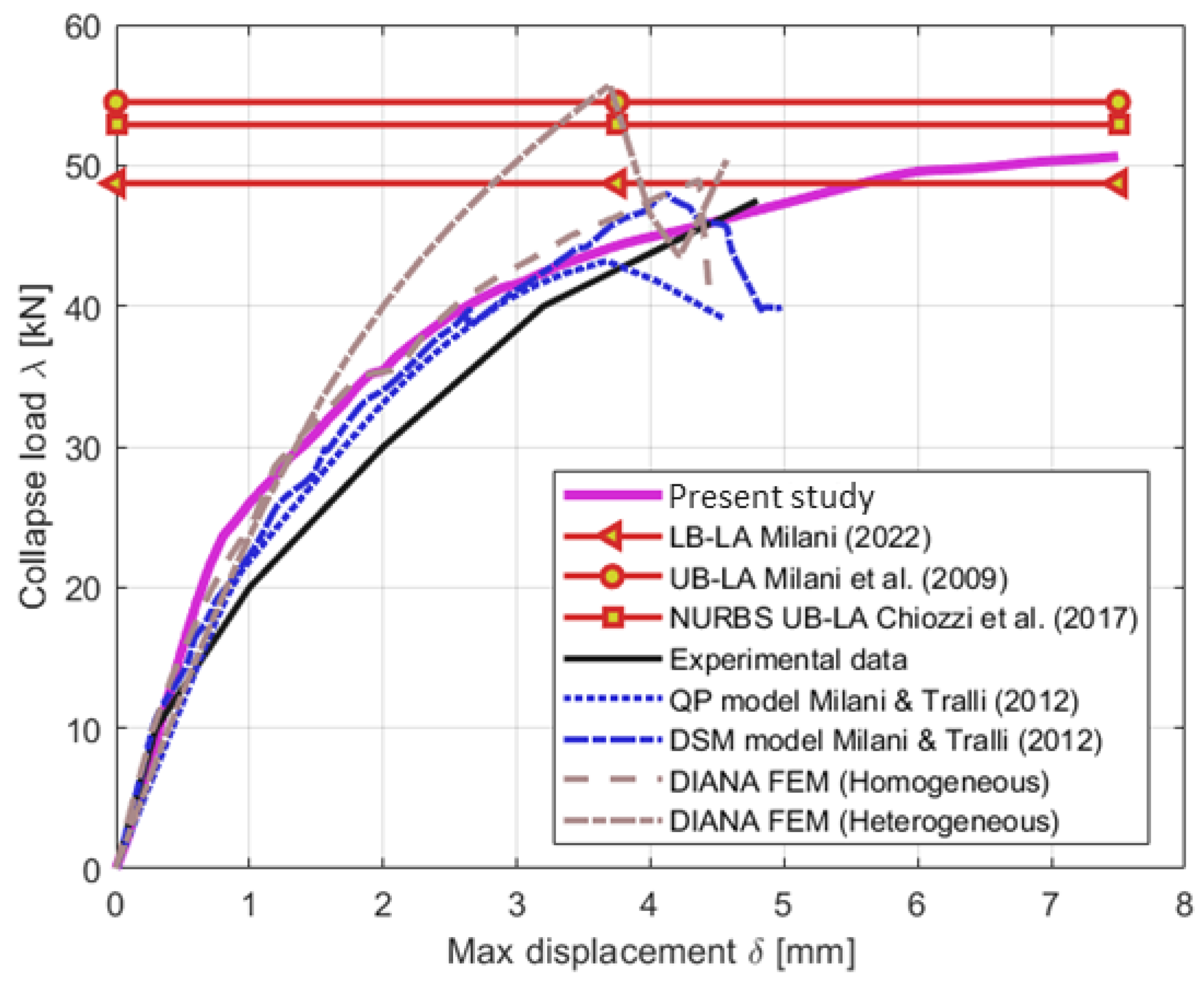
The chart in
Figure 7 shows the validation of the best result from the sensitivity analysis against those coming from the FE [
1,
3,
4,
7,
8] approaches from literature.
2.3. Elastic Perfectly Ductile Cutoff Bars Applied to FRP Hoop Reinforcement
In order to prove the efficacy of applying hoop reinforcement on the extrados of domes, FRP strips have been simulated by the addition of elastic perfectly ductile CoBs [
11,
12,
13,
14,
15,
16] with mechanical parameters and relative positions derived from [
1,
17,
17].
The following chart in
Figure 8 contains the collapse load computed by LA and DEM [
1]. As the reader may note, the agreement between final results is satisfying enough. The area in between the DEM curve (DIANA model, blue dotted line) and the FEM curve resulting from this method is due to a different way of modelling (more discretised nonlinearity in the DIANA model [
1]). Compared to the upper-bound LA, the FE model is shown to be more conservative but proves that FRP strips increase the collapse load of a dome by preventing the formation of meridian cracks.
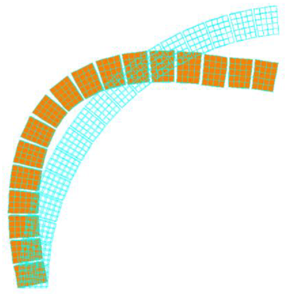
The following
Figure 9 indicates where the FRP strips exert their confinement action against the formation of meridian cracks and an annular hinge. By comparison between
Figure 9 and
Figure 6, the efficacy of FRP reinforcement is shown.
3. Conclusions
To recap the results that were obtained, the first method models masonry nonlinearity using elastic perfectly brittle PC, neglecting most of masonry’s tensile resistance (by Heyman’s hypotheses). Whereas in the second method, masonry nonlinearity is expressed by elastic perfectly plastic CoBs. The brittle behaviour of the first model ends in providing an accurate position of the plastic hinge but also a very conservative value in terms of collapse load. The contrary is achieved by the ductility imposed in the second model. This one was used as a baseline for the application of FRP strips, again by the addition of ductile CoBs. Indeed, the collapse load computed for the reinforced case (
Figure 8) was almost twice that of the unreinforced case (
Figure 9), demonstrating the efficacy of such interventions. The method itself proved to be robust and is therefore a very useful and practical way to model such additions for retrofitting or safety purposes.
Despite the simplicity of the modelling and the short computational time, the present method can be further implemented with automatic choices depending on some initial data to be input (from standards or surveys).
The methods can be applied to real masonry hemispherical domes, both in unreinforced and reinforced cases. They have both proven to be numerically stable and robust; useful for the purpose of verification (the first in finding the intermediate plastic hinge position, and the second and third in finding the collapse load); and to be trustworthy (by comparison with the analytical and numerical results). Hence, they may easily be used in professional life in parallel or in substitution of LA.
Author Contributions
Conceptualization, A.G., N.P. and G.M.; methodology, A.G., N.P. and G.M.; validation, A.G. and N.P.; formal analysis, A.G., N.P. and G.M.; investigation, A.G., N.P. and G.M.; resources, G.M.; data curation, A.G., N.P. and G.M.; writing—original draft preparation, A.G., N.P. and G.M.; writing—review and editing, A.G., N.P. and G.M.; visualization, A.G. and N.P.; supervision, G.M. All authors have read and agreed to the published version of the manuscript.
Funding
The study presented in the paper was partially developed within the research activities carried out in the frame of 2022-2024 ReLUIS Project—WP10 Masonry Structures (Coordinator—Guido Magenes). Such project has been funded by the Italian Department of Civil Protection. Note that the opinions and conclusions presented by the authors do not necessarily reflect those of the funding entity. The study was also partially developed within the studies carried out in the research project 2022-2024 MAECI financed by the Italian Ministry of Foreign affairs under the grant CUP D23C22000060006 and by the Department of Science and Technology (International Corporation Division), India under the research grant INT/Italy/P-29/2022. PIs are for the Italian part Gabriele Milani and for the Indian part Siddhartha Ghosh. The aforementioned funding agencies are not responsible for the findings and conclusions reported in this paper.
Institutional Review Board Statement
Not applicable.
Informed Consent Statement
Not applicable.
Data Availability Statement
Data will be made available on request.
Conflicts of Interest
The authors declare no conflict of interest.
References
- Milani, G.; Milani, E.; Tralli, A. Upper bound limit analysis model for FRP–reinforced masonry curved structures. Part II: Structural analyses. Comput. Struct. 2009, 87, 1534–1558. [Google Scholar] [CrossRef]
- Foraboschi, P. Strengthening of Masonry Arches with Fiber-Reinforced Polymer Strips. J. Compos. Constr. 2004, 8, 191–202. [Google Scholar] [CrossRef]
- Creazza, G.; Matteazzi, R.; Saetta, A.; Vitaliani, R. Analyses of Masonry Vaults: A Macro Approach based on Three-Dimensional Damage Model. J. Struct. Eng. 2002, 128, 646–654. [Google Scholar] [CrossRef]
- Creazza, G.; Saetta, A.; Matteazzi, R.; Vitaliani, R. Analyses of masonry vaulted structures by using 3-D damage model. In Proceedings of the European Congress on Computational Methods in Applied Sciences and Engineering, ECCOMAS 2000, Barcelona, Spain, 11–14 September 2000; pp. 11–14. [Google Scholar]
- Milani, G. Closed form solutions in limit analysis for masonry cloister vaults and domes subjected to concentrated vertical loads applied at the top crown. Int. J. Mason. Res. Innov. 2023. [Google Scholar] [CrossRef]
- Milani, E.; Milani, G.; Tralli, A. Limit analysis of masonry vaults by means of curved shell finite elements and homogenization. Int. J. Solids Struct. 2008, 45, 5258–5288. [Google Scholar] [CrossRef]
- Milani, G. Simple lower bound limit analysis model for masonry double curvature structures. Comput. Struct. 2022, 269, 106831. [Google Scholar] [CrossRef]
- Chiozzi, A.; Milani, G.; Tralli, A. A Genetic Algorithm NURBS-based new approach for fast kinematic limit analysis of masonry vaults. Comput. Struct. 2017, 182, 187–204. [Google Scholar] [CrossRef]
- Aita, D.; Milani, G.; Taliercio, A. Limit analysis of masonry domes with oculus and lantern: A comparison between different approaches. Math. Mech. Solids 2023. [Google Scholar] [CrossRef]
- Pavlovic, M.; Reccia, E.; Cecchi, A. A Procedure to Investigate the Collapse Behavior of Masonry Domes: Some Meaningful Cases. Int. J. Arch. Heritage 2016, 10, 67–83. [Google Scholar] [CrossRef]
- Pingaro, N.; Milani, G. Simple non-linear numerical modelling of masonry arches reinforced with SRG using elasto-fragile and elasto-ductile truss finite elements. Eng. Struct. 2023, 293, 116637. [Google Scholar] [CrossRef]
- Gandolfi, A.; Pingaro, N.; Milani, G. Simple non-linear numerical modelling for unreinforced and FRP-reinforced masonry domes. Buildings 2023, In press. [Google Scholar]
- Milani, G.; Tralli, A. A simple meso-macro model based on SQP for the non-linear analysis of masonry double curvature structures. Int. J. Solids Struct. 2012, 49, 808–834. [Google Scholar] [CrossRef]
- Pingaro, N.; Calabrese, A.S.; Milani, G.; Poggi, C. Debonding sawtooth analytical model and FE implementation with in-house experimental validation for SRG-strengthened joints subjected to direct shear. Compos. Struct. 2023, 319, 117113. [Google Scholar] [CrossRef]
- Milani, G. Simple model with in-parallel elasto-fragile trusses to characterize debonding on FRP-reinforced flat substrates. Compos. Struct. 2022, 296, 115874. [Google Scholar] [CrossRef]
- Bertolesi, E.; Milani, G.; Fedele, R. Fast and reliable non-linear heterogeneous FE approach for the analysis of FRP-reinforced masonry arches. Compos. B Eng. 2016, 88, 189–200. [Google Scholar] [CrossRef]
- CNR-DT 200 R1/2013; Istruzioni per la Progettazione, l’Esecuzione ed il Controllo di Interventi di Consolidamento Statico mediante l’utilizzo di Compositi Fibrorinforzati.Materiali, strutture di c.a. e di c.a.p., Strutture Murarie. Consiglio Nazionale Ricerche: Rome, Italy, 2013.
| Disclaimer/Publisher’s Note: The statements, opinions and data contained in all publications are solely those of the individual author(s) and contributor(s) and not of MDPI and/or the editor(s). MDPI and/or the editor(s) disclaim responsibility for any injury to people or property resulting from any ideas, methods, instructions or products referred to in the content. |
© 2023 by the authors. Licensee MDPI, Basel, Switzerland. This article is an open access article distributed under the terms and conditions of the Creative Commons Attribution (CC BY) license (https://creativecommons.org/licenses/by/4.0/).


