Abstract
The ankle exoskeleton is an auxiliary device designed to restore human independence. This paper proposes the development and initial testing of a passive ankle exoskeleton designed for movements with dorsal and plantar flexion. The device also includes a new mechanism design with four electric linear actuators, and the shank platform and the foot platform are connected to the ball by a swivel joint. Mechanical tests demonstrate the ability of the prototype to function adequately in the natural range of the ankle joint. Preliminary results show that the exoskeleton can reduce the activation of the calf muscles on the limb on which the device is installed. In the investigation of a passive ankle joint exoskeleton designed for movements with dorsal and plantar flexion, numerical test results can be highlighted by focusing on parameters such as speed, acceleration, and translation moment. These measurements provide valuable information about the performance and effectiveness of the exoskeleton. By focusing on these numerical test results, it is possible to obtain an idea of the performance of the exoskeleton, understand its impact on the movements of the ankle joint, and make informed decisions for further improvements or optimization of the design.
1. Introduction
Every year, millions of people around the world suffer from motor disabilities caused by a spinal cord injury (SCI), stroke, or cerebral palsy. These people suffer from a reduced muscular control capacity, manifested by a reduced torque generation and a lack of ability to modulate the mechanical impedance around the joints. They often experience symptomatic muscle control, for example, because of spasticity [1,2,3].
Exoskeletons are wearable devices that augment human movement and have been widely used in various fields, including military, healthcare, and sports.
Effective rehabilitation is a long-term process that also requires a trained physical therapist to help restore joint mobility. Therefore, robotics has been involved in rehabilitation therapy for constant patient observation and assisted motion [4].
Physiotherapy is one of the areas of medicine in which engineering works. Several devices designed to improve and support therapy are being studied and developed there. Mechanics and electronics, together with physiotherapy, are developing exoskeletons, which are electromechanical devices attached to limbs that can help the user move or adjust the movement of these limbs, providing automatic therapy with flexible and customizable programs to improve autonomy and meet the needs of each patient. Exoskeletons can increase the effectiveness of physiotherapy and shorten the rehabilitation time of patients [5,6].
Most past robotic designs are based on the static platform design, where a non-portable device requires the patient to hold a foot on a grounded platform (usually sitting) to perform rehabilitation [7,8,9,10]. Most of these structures are not only bulky, but also stationary in the field. Thus, patients must visit a hospital or an establishment where a rehabilitation device is installed, despite the potential impairment of mobility.
The Almaty ankle exoskeleton is a device designed to enhance the function of the ankle joint. Ankle exoskeletons have the potential to improve mobility and reduce the risk of injury in individuals with lower limb impairments.
The purpose of this article is to provide an overview of the development and testing of an ankle exoskeleton, including the design process, testing and evaluation, and potential applications. This article aims to provide a better understanding of ankle exoskeletons and their potential benefits, limitations, and challenges to inform future research and development in this field.
The virtual model of the device for rehabilitation of the ankle of the third degree of freedom, capable of performing all the necessary physical exercises, is shown in Figure 1.
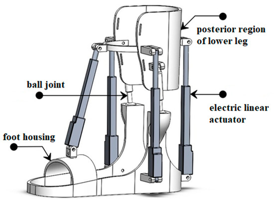
Figure 1.
Virtual model.
2. Background
Exoskeletons have been around for decades, starting from the development of full-body exoskeletons for military purposes in the 1960s. Since then, exoskeleton technology has advanced rapidly, and a variety of exoskeletons have been developed to improve mobility, strength, and endurance in individuals with mobility impairments, sports athletes, and military personnel [11,12].
Exoskeletons can be categorized into two types: passive and active. Passive exoskeletons use mechanical elements, such as springs or dampers, to reduce the load on the human body during movement, while active exoskeletons use actuators to provide external forces to assist or replace the human muscles.
Ankle exoskeletons, specifically, are designed to augment the function of the ankle joint, which plays a critical role in human mobility. Ankle exoskeletons can be passive or active and can aid during walking, running, and jumping. They have the potential to improve mobility and reduce the risk of injury in individuals with lower limb impairments, such as stroke survivors or individuals with cerebral palsy.
Research on ankle exoskeletons has grown significantly over the past decade, and several prototypes have been developed and tested in laboratory and clinical settings. The design of ankle exoskeletons is still a challenge, as the device must provide sufficient support and assistance without restricting natural human movement or causing discomfort. Additionally, the effectiveness of ankle exoskeletons varies depending on the individual’s gait pattern, body weight, and other factors.
3. Kinematic Design
The four-actuator ankle exoskeleton is a wearable device that can help or enhance ankle movements. The exoskeleton is designed to be placed around the tibia and foot and is powered by four electric motors that are connected to the ankle by transmission systems.
The exoskeleton case is made of PLA plastic, which is a biodegradable thermoplastic material widely used in 3D printing. PLA plastic is lightweight, durable, and easy to mold, making it the ideal material for custom-made exoskeletons.
The degree of freedom (DOF) of an ankle exoskeleton refers to the number of independent directions in which it can move. Generally, ankle exoskeletons are designed to provide one DOF, corresponding to plantarflexion and dorsiflexion movements.
The spatial mechanism of the ankle exoskeleton involves a combination of rigid and flexible components that work together to achieve the desired range of motion. The mechanism typically includes a footplate that attaches to the wearer’s foot and a rigid frame that attaches to the lower leg. The footplate is connected to the frame by a hinge joint that allows for rotation in the sagittal plane, corresponding to plantarflexion and dorsiflexion movements.
According to Figure 2, it can be calculated by the formula calculated by the Somov–Malyshev formula, the number of degrees of freedom of the mechanism for the spatial kinematic structure is determined as follows:
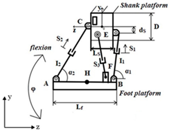
Figure 2.
Kinematic design with parameters.
The application of this formula is possible if no additional conditions are imposed on the movements of the links that make up the mechanism (the axes of all rotational pairs were parallel, intersected at one point, etc.). These additional requirements change the nature of the movements of the mechanism and, accordingly, change the form of its structural formula.
In a spherical mechanism, all three kinematic chains impose the same connections, and the axes of all pairs intersect at one point. In the proposed design, there are three power screws and three kinematic mutual screws. These are the zero parameter screws. To determine the number of degrees of freedom, we apply the Dobrowolski formula:
If the last rotational pairs are replaced by spherical ones, then in this case each chain imposes one bond. The number of degrees of freedom is determined by the Somov–Malyshev formula:
4. Hardware Architecture and Mathematical Modeling
Hardware architecture and mathematical modeling are two important aspects of many technological systems, including exoskeletons used for rehabilitation or other applications.
The hardware architecture of the exoskeleton is crucial for its performance, security, and functionality. It includes solutions related to the type of materials used, mechanical design, placement of the sensor and actuator, power supply, and communication interfaces. Hardware architecture is usually designed with specific exoskeleton requirements in mind, such as desired range of motion, strength, weight, and durability.
To develop a mechatronic design of a rehabilitation device for ankle joint rehabilitation, several methods were used, such as the introduction of quality functionality, industrial, and structural designs. The proposed three-dimensional rehabilitation device consists of a foot platform and elements controlled by four linear electric actuators. Thanks to this, with the help of this device, it is possible to achieve natural movements of the ankle joint. In addition, this device provides an extensive workspace that provides the necessary movement of the lower part of the leg. Figure 3 illustrates the comprehensive rehabilitation system.
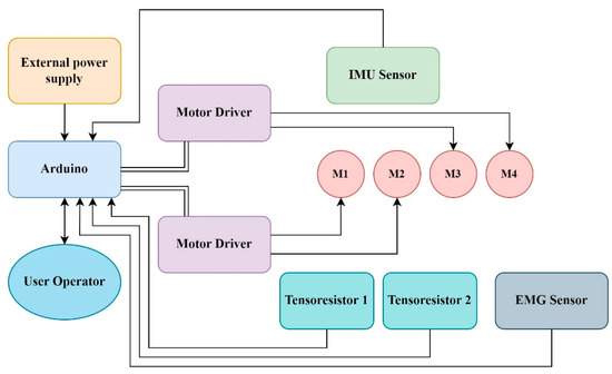
Figure 3.
Hardware architecture.
Given the three movements, it is very difficult to simulate the dynamics regulating the operation of the ankle rehabilitation device, since the overall system is nonlinear. Due to some practical conclusions, the main task of mechatronics is to control devices using simplified models. Thus, they can be made more resistant to some external influences. In this regard, the individual dynamics of the ankle joint rehabilitation device for controlling the main movements were first considered. The main reason is that during passive rehabilitation, certain types of exercises are performed first, which ensure the stability and functionality of the ankle joint.
Mathematical modeling involves the use of mathematical equations and methods to describe and analyze the behavior or characteristics of a system. In the context of exoskeletons, mathematical modeling can be used to describe mechanical, electrical, and control aspects of a system, as well as interactions with the human body.
Mathematical models can be used to model and predict the behavior of an exoskeleton, such as its kinematics (motion), dynamics (forces and torques), and control algorithms. These models can help in understanding the performance, stability, and safety of the exoskeleton and can also be used to optimize design, evaluate performance, and develop control algorithms.
Consider Figure 4, where determines the angle of movement of dorsiflexion and plantar flexion, is an absolute coordinate system, is a movable coordinate system, determines the beam of force, because the force comes from some part of the weight of the ankle (the weight of the entire foot is not provided, since the patient relies only on, for example, if we take the patient’s sitting position), then it also describes the stiffness of the tibial–ankle joint, is a constant distance, and is the torque transmitted by the motor to adjust the angular orientation.
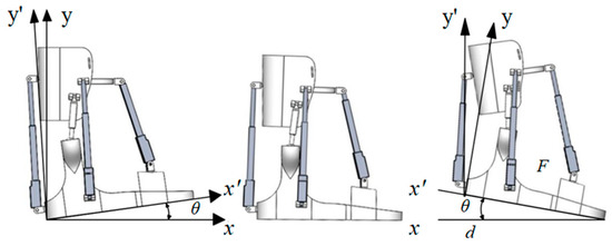
Figure 4.
Angle describing dorsiflexion and plantarflexion movements θ.
For the control of the angular position during the dorsiflexion and plantarflexion movements of the foot platform, only individual dynamics are provided, not for combined movements. The mathematical model that governs the dynamics of motion can be obtained by applying Newton’s second law:
where is the moment of inertia and is the coefficient of friction.
It is recommended to use the PID controller to realize the desired position according to predetermined trajectories.
The dynamics of a closed system with a controller controlling the trajectory proposed above, the error of which , is given as follows:
.
The parameters , , and are chosen so that the characteristic polynomial (3) is the Hurwitz polynomial to ensure that the model dynamics are globally asymptotically constant.
The desired trajectory of motion is given by the following Bezier polynomial:
where and are the initial and final necessary positions, thus the rehabilitation process is carried out by slowly and smoothly moving from the initial position to the next position.
5. Experimental Test Bed for Prototype
The four electric drives in the exoskeleton provide the necessary force to help or increase ankle movement. The motors can be controlled by a microcontroller, which can adjust the speed and direction of rotation of the motors depending on the movement of the user.
As shown in Figure 5, the ankle joint rehabilitation system that we have implemented consists mainly of a PC (personal computer), a microcontroller, an activated exoskeleton, and a device for recording myoelectric signals (EMG). The PC has three functions: it interacts with the operator (who may be a therapist or even the patient himself) using a graphical interface, registers and processes the patient’s myoelectric signals, and, finally, communicates with the microcontroller via a serial connection to transmit commands or receive sensory information. The microcontroller generates the necessary control signals for the drives and monitors their actual position using sensors on them. The actuators affect the exoskeleton of the patient.
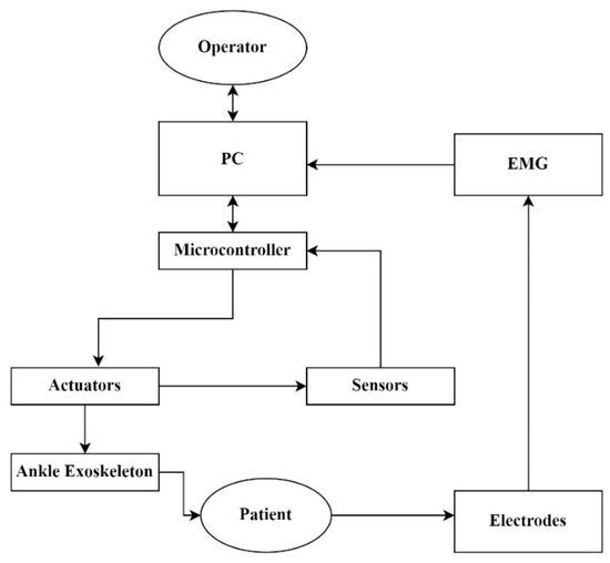
Figure 5.
Technological control scheme of the ankle exoskeleton for rehabilitation.
The exoskeleton can be used to rehabilitate after an ankle injury, to help people with mobility impairments, or to improve athletes’ performance. The exoskeleton can be customized for each individual user to ensure convenient fit and optimal performance.
As shown in Figure 6, the description is a prototype of an ankle exoskeleton with four electric linear actuators, consisting of the following components:
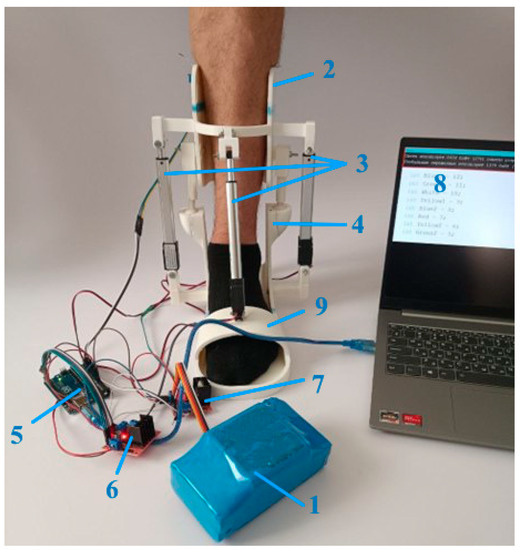
Figure 6.
Experiment test bed: 1—battery, 2—shank platform, 3—actuators, 4—ball joint, 5—microcontroller, 6, 7—drivers, 8—PC, 9—foot platform.
- Lower body: This component provides structural support and contains exoskeleton components.
- Rear drive mounting: The rear drive mount serves as the attachment point for the rear of the exoskeleton, providing stability and alignment.
- Front-wheel drive mounts: Front-wheel drive mounts fix and position the front of the exoskeleton, contributing to stability and alignment.
- Electric Linear Actuator (S1): Located at the front, this electric linear actuator creates linear motion to aid or resist certain ankle movements.
- Electric linear actuator (S2): An electric linear actuator located at the rear provides actuation of the movements of the ankle joint.
- Electric Linear Actuator (S3): Located on the right side, this electric linear actuator is associated with a certain movement of the ankle and promotes assistance or resistance.
- Electric Linear actuator (S4): Located on the left side, this electric linear actuator is responsible for actuating the movements of the ankle joint.
- Installation of the right drive: This component refers to the attachment mechanism for attaching the components of the right drive of the exoskeleton.
- Left drive attachment: Similarly, this component is an attachment mechanism for attaching the components of the left drive of the exoskeleton.
- Foot housing: This component provides the support and structure of the user’s foot inside the exoskeleton.
The exoskeleton provides actuation and control of the movements of the ankle joint using four electric linear actuators. The front drives (S1 and S2) provide forward and backward movement, and the side drives (S3 and S4) facilitate lateral movements. This configuration provides coordinated and targeted assistance or resistance to certain movements of the ankle joint.
6. Experimental Testing of a Prototype
After the design and development of the four linear electric drives, their performance was tested and evaluated to ensure that they met the required specifications. The testing and evaluation process typically involves several key steps:
- Functional testing: The first step is to perform functional testing to ensure that each of the linear electric drive’s functions correctly. This includes testing the engine, gearbox, and other mechanical components as well as control electronics and software.
- Load testing: After completion of functional testing, the next step is to perform load testing. This includes applying the required loads and effort to linear electric drives to ensure that they can handle the required workload.
- Speed testing: In addition to load testing, speed testing is also required to ensure that linear electric drives can reach the required speed. This includes speed testing under different loads and conditions to ensure that it meets the required specifications.
- Durability check: To ensure the durability of linear electric drives and their ability to withstand long-term use, it is also necessary to test their durability. This includes multiple uses of actuators to simulate long-term use and identify any potential durability problems.
- Safety check: Finally, a safety check is also necessary to ensure the safety of linear electric actuators. This includes checking for potential hazards such as electrical shock or mechanical failure and ensuring that the actuators meet all necessary safety standards and regulations.
Overall, the testing and evaluation process is crucial to ensure that linear electric drives meet the required specifications and are safe and reliable in use. Any problems identified during testing should be addressed before the drives are put into production and used in real applications.
The possibility of dorsiflexion and plantarflexion positions of the ankle joint depends on several factors, including the anatomy of the joint, the integrity of the surrounding ligaments, and the strength and flexibility of the muscles involved.
Figure 7 shows the movements of the platform that the exoskeleton used to rehabilitate the ankle joint during testing of the device, which vary depending on several factors, including the specific goals of rehabilitation, the condition and needs of the person undergoing rehabilitation, as well as the design and capabilities of the exoskeleton itself.
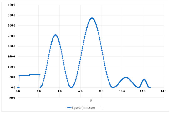
Figure 7.
The results of testing the device in the position of the back and plantar flexion of the ankle joint speed.
Judging by the graph, movements in all directions have peaks of maximum values of 350 deg/s2 in 12 s.
During device testing, the speed of the exoskeleton can be adjusted to achieve specific rehabilitation goals, such as improving range of motion, strength, balance, or gait. It is important that the speed of the exoskeleton is set at a level that is safe and suitable for a person undergoing rehabilitation to avoid any potential risk or discomfort.
The exoskeleton has adjustable settings that allow the user to adjust the speed individually and gradually over time as the human condition improves. The speed may start at a slower pace and gradually increase as the person’s ability to tolerate and benefit from the rehabilitation program improves.
It is important to note that the appropriate speed for the rehabilitation of the ankle joint with an exoskeleton during the testing of the device should always be determined by a qualified medical professional or therapist who will consider the specific needs and condition of the person and follow the established protocols and recommendations for rehabilitation to ensure safety and effective rehabilitation results.
Figure 8 shows the acceleration of the exoskeleton used for ankle rehabilitation. During testing, the device may vary depending on several factors, including the specific goals of rehabilitation, the condition and needs of the person undergoing rehabilitation, as well as the design and capabilities of the exoskeleton itself.
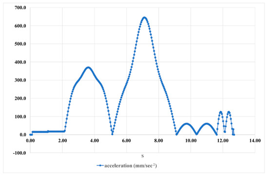
Figure 8.
The results of testing the device in the position of the back and plantar flexion of the ankle joint acceleration.
Acceleration can affect the comfort, safety, and effectiveness of the rehabilitation process.
During testing of the device, the acceleration of the exoskeleton can be adjusted depending on the person’s condition, progress, and comfort level, as well as any specific protocols or guidelines for rehabilitation.
Exoskeletons used for ankle joint rehabilitation can have adjustable acceleration parameters, which allows individual and progressive adjustments to be made over time as a person’s condition improves. Acceleration can start at a lower level and gradually increase as a person’s ability to tolerate and benefit from a rehabilitation program improves.
The translational motion relative to the angle is shown in Figure 9, which shows 14 s of 60 Newton-seconds. The translational moment, also known as the moment arm or lever arm, of an exoskeleton used for ankle joint rehabilitation during device testing refers to the distance between the axis of rotation of the ankle joint and the line of force. It determines the torque or rotational force applied to the ankle joint, which can affect the biomechanics and effectiveness of the rehabilitation process.
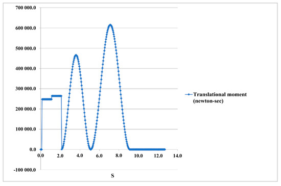
Figure 9.
The results of testing the device in the position of the back and plantar flexion of the ankle joint—translation moment.
The translational moment can be set in such a way as to provide an appropriate level of load and stimulation of the ankle joint without causing discomfort or risk of injury.
7. Conclusions
In conclusion, the design and development of four linear electric drives involves several key steps, including specification of requirements, component selection, mechanical system design, electrical system integration, prototype development, testing, and production. The testing and evaluation process is critical to ensure that the linear electric drives meet the required specifications and are safe and reliable to use. These drives have a wide range of potential applications across various industries, including industrial automation, robotics, aerospace and defense, medical devices, automotive, and entertainment. As technology continues to advance, the use of linear electric drives is likely to increase, providing efficient, precise, and reliable linear motion for various applications. It is important to note that for the rehabilitation of the ankle joint using an exoskeleton during testing, the devices should always be determined by a qualified medical professional or therapist who will consider the specific needs and condition of the person and follow the established protocols and recommendations for rehabilitation to ensure safe and effective rehabilitation results. During the rehabilitation process, it may be necessary to regularly monitor and adjust the parameters of the translational moment to optimize the benefits and safety of ankle rehabilitation using an exoskeleton.
Author Contributions
Conceptualization, N.Z., T.I. and G.B.; methodology, N.Z.; software, N.Z. and G.B.; data analysis, N.Z., G.B. and B.B.; data interpretation, N.Z. and G.B.; writing—preparation, N.Z. and T.I.; writing—editing, N.Z. and T.I.; visualization, N.Z. All authors have read and agreed to the published version of the manuscript.
Funding
This research has been funded by the Ministry of Science and Higher Education of the Republic of Kazakhstan, Grant No. AP14972221.
Institutional Review Board Statement
Not applicable.
Informed Consent Statement
Not applicable.
Data Availability Statement
Data are obtained in the article.
Conflicts of Interest
The authors declare no conflict of interest.
References
- Nasiri, R.; Shushtari, M.; Arami, A. An Adaptive Assistance Controller to Optimize the Exoskeleton Contribution in Rehabilitation. Robotics 2021, 10, 95. [Google Scholar] [CrossRef]
- Lance, J.W. The control of muscle tone, reflexes, and movement: Robert Wartenbeg Lecture. Neurology 1980, 30, 1303–1313. [Google Scholar] [CrossRef] [PubMed]
- Cha, Y.; Arami, A. Quantitative Modeling of Spasticity for Clinical Assessment, Treatment and Rehabilitation. Sensors 2020, 20, 5046. [Google Scholar] [CrossRef]
- Velandia, C.C.; Tibaduiza, D.A.; Vejar, M.A. Proposal of Novel Model for a 2 DOF Exoskeleton for Lower-Limb Rehabilitation. Robotics 2017, 6, 20. [Google Scholar] [CrossRef]
- Venkata Sai Prathyush, I.; Ceccarelli, M.; Russo, M. Control Design for CABLEankle, a Cable Driven Manipulator for Ankle Motion Assistance. Actuators 2022, 11, 63. [Google Scholar] [CrossRef]
- Alvarez-Perez, M.G.; Garcia-Murillo, M.A.; Cervantes-Sánchez, J.J. Robot-assisted ankle rehabilitation: A review. Disabil. Rehabil. Assist. Technol. 2020, 15, 394–408. [Google Scholar] [CrossRef] [PubMed]
- Jamwal, P.K.; Hussain, S.; Ghayesh, M.H.; Rogozina, S.V. Impedance Control of an Intrinsically Compliant Parallel Ankle Rehabilitation Robot. IEEE Trans. Ind. Electron. 2016, 63, 3638–3647. [Google Scholar] [CrossRef]
- Rodríguez-León, J.F.; Chaparro-Rico, B.D.M.; Russo, M.; Cafolla, D. An Autotuning Cable-Driven Device for Home Rehabilitation. J. Health Eng. 2021, 2021, 6680762. [Google Scholar] [CrossRef] [PubMed]
- Sung, E.; Slocum, A.H.; Ma, R.; Bean, J.F.; Culpepper, M.L. Design of an Ankle Rehabilitation Device Using Compliant Mechanisms. J. Med. Devices 2011, 5, 011001. [Google Scholar] [CrossRef]
- Nurahmi, L.; Caro, S.; Solichin, M. A novel ankle rehabilitation device based on a reconfigurable 3-RPS parallel manipulator. Mech. Mach. Theory 2019, 134, 135–150. [Google Scholar] [CrossRef]
- Zhetenbayev, N.; Balbayev, G.; Iliev, T.; Bakhtiyar, B. Exoskeleton for the Ankle Joint Design and Control System. In Proceedings of the 2022 International Conference on Communications, Information, Electronic and Energy Systems (CIEES), Veliko Tarnovo, Bulgaria, 24–26 November 2022; pp. 1–6. [Google Scholar] [CrossRef]
- Zhetenbayev, N.; Balbayev, G.; Aknur, D.; Zhauyt, A.; Shingissov, B. Developing of a wearable ankle rehabilitation robotic device. Vibroeng. Procedia 2023, 48, 36–41. [Google Scholar] [CrossRef]


Disclaimer/Publisher’s Note: The statements, opinions and data contained in all publications are solely those of the individual author(s) and contributor(s) and not of MDPI and/or the editor(s). MDPI and/or the editor(s) disclaim responsibility for any injury to people or property resulting from any ideas, methods, instructions or products referred to in the content. |
© 2023 by the authors. Licensee MDPI, Basel, Switzerland. This article is an open access article distributed under the terms and conditions of the Creative Commons Attribution (CC BY) license (https://creativecommons.org/licenses/by/4.0/).