1. Introduction
Building automation (BA) and control systems are a collection of automated systems [
1]. Each building is equipped with multiple subsystems that ensure its functionality (e.g., electrical, plumbing, lighting, heating, ventilation and air conditioning—HVAC, etc.) [
2,
3]. The “smart home” technology, which was talked about and written about a lot in recent years, is probably the closest to the idea of an intelligent building [
4,
5,
6]. The progress of BA technologies paves the way for new systems and applications characterized by intuitiveness, flexibility and more autonomous behavior [
7]. The expectations of specialists are that they become part of the environment in which people perform their tasks and live. It is believed that today’s user interface will gradually be replaced by technologies that allow communication in smart buildings to be based on speech, gestures and emotions [
8]. Thus, based on human–computer interaction, it will move to human–computer cooperation. The development of smart buildings is also inextricably linked with new materials, micro- and nanoelectronics and technologies for the production of microsystems, including biomicrotechnology. It includes the use of sensors to measure blood pressure, temperature, weight, respiratory activity, to monitor eating patterns, gait, sleep and others. This highlights, again, the complexity of the “smart home” strategy. Technological development naturally leads to the creation of new opportunities to help and facilitate people’s lives. This is a challenge that implies the continuous monitoring of all changes and combining the results of different technological fields into useful concepts. Modern buildings require advanced control systems, an example of which is given in
Figure 1. The hierarchy structure of the building system consists of three levels vertically, which is fundamental for the control strategy. The so-called “field level” is formed with the English term: field bus level. Through the field devices, such as sensors and actuators, the control laws can be applied. Different communication protocols are increasingly used in various company’s solutions like ZigBee, Bluetooth, Wi-Fi, LoRaWAN, etc. The second level is known as a “control level”. It contains the control devices themselves and industrial networks. The “high level” can be assumed as a management level—allowing both monitoring and implementation of some control functions [
1]. Usually, it is associated with software for Supervisory Control and Data Acquisition (SCADA). Many specialized environments can be used for the development of this layer—DesigoCC [
9], EcoStructure Building [
10], Open SCADA [
11,
12], etc.
The fieldbus level is a basis that includes many and various devices that allow the management of technological quantities such as indoor/outdoor temperature sensors, analog/digital control valves, humidity and pressure sensors, freezing and boiling temperature sensors, communication modules, etc. Automation equipment manufacturers are grouped into various organizations supporting one or another field communication standard. The communications at the Fieldbus level determines greater market share. Hence, many of the established specifications for field networks were originally developed as company concepts. For this reason, despite the widely declared openness of field networks, in practice, devices from different manufacturers are not compatible. Widely used communication protocols are ZigBee, Bluetooth, Wi-Fi. The second level takes place mainly in the distributed hierarchy of the BA and ensures demands intersection between other layers. At this place, the real-time process control is conducted, and the configuration and interaction of various types of controllers, personal computers, operator stations, diagnostic and programming devices are performed. The appropriate communication protocols, which take place here, are DALI, KNX, LonWorks and Modbus. The high level defines and collects all control tasks of the whole building. At this place, the software development for parameter monitoring, as a SCADA projects, management of the resource and cost planning, time schedules and reference settings are included. The database collection may properly be stored in cloud or dedicated servers. A benchmark of a room-heating system is considered to illustrate the benefits of the design paradigm using fuzzy logic. The benefit of the work is that to apply intuitive logic to the heating room model with an easy way to shift the results to real building management system—BMS, a part of BA. The main idea of the work is to develop and to apply fuzzy control action for temperature stabilisation in building heating system. This way can improve and obtain better transient response compared to the case with bigger disturbance (outside temperature) that classical control is not able to deal with and it can keep the response quality. Furthermore, the experimental results can be used in more complex control strategies applied to the plants with variable parameters. The paper is organized as follows: Section Basic fuzzy logic expression is devoted to the fuzzy logic statement and control development; Section A Building automation description describes the building floor model and structure of the BA; the control system structure in simulation environment is presented in Section Control system design; the experiment statements and transient responses results are given in Sections Simulation experiments and Results, respectively; in the last section, Conclusions, the advantages of the developed application are summarized.
2. Basic Fuzzy Logic Statements
Fuzzy control uses fuzzy linguistic variables. It is based on the concept of fuzzy logic. In so-called artificial intelligence, fuzzy logic takes a major part. It was introduced in the mid-twentieth century and was proposed by Lotfi Zadeh. In order to clarify its essence, a comparison will be made again with classical theory, or, more precisely, with classical logic. In that meaning, it is ordinary logic, i.e., every conclusion is made by the simple construction.
Fuzzy set theory was born in 1965 with the article “Fuzzy sets” in the journal
Informatics and Management by Prof. Lotfi Zadeh from the University of California, USA. He developed fuzzy set theory as a mathematical discipline, although the main ideas were already presented earlier by philosophers and analysts. The great interest in fuzzy sets started in the 1970s with their practical application in a number of technical disciplines. In automatic control systems, it entered in the 1980s, together with the appearance of the first fuzzy controllers—fuzzy control systems, which form one of the areas of artificial intelligence systems, also date from that time. The fuzzy control theory is one that uses fuzzy linguistic variables. It is based on the concept of fuzzy logic. In order to clarify its essence, a comparison will be made again with classical theory, or, more precisely, with classical logic. From the classical point of view, every conclusion is made according to the simple construction:
Therefore, the general form of the rules—R
i—is:
where:
x is the input (premise) linguistic variable, Aj is the linguistic value (fuzzy set), which is active for the i-th rule,
j = 1, 2, …, N is the fuzzy sets number of x.
y is the output (consequence) linguistic variable, Bj is the linguistic value (fuzzy set), which is active for the j-th rule,
j = 1, 2, …, M is the fuzzy sets number of y.
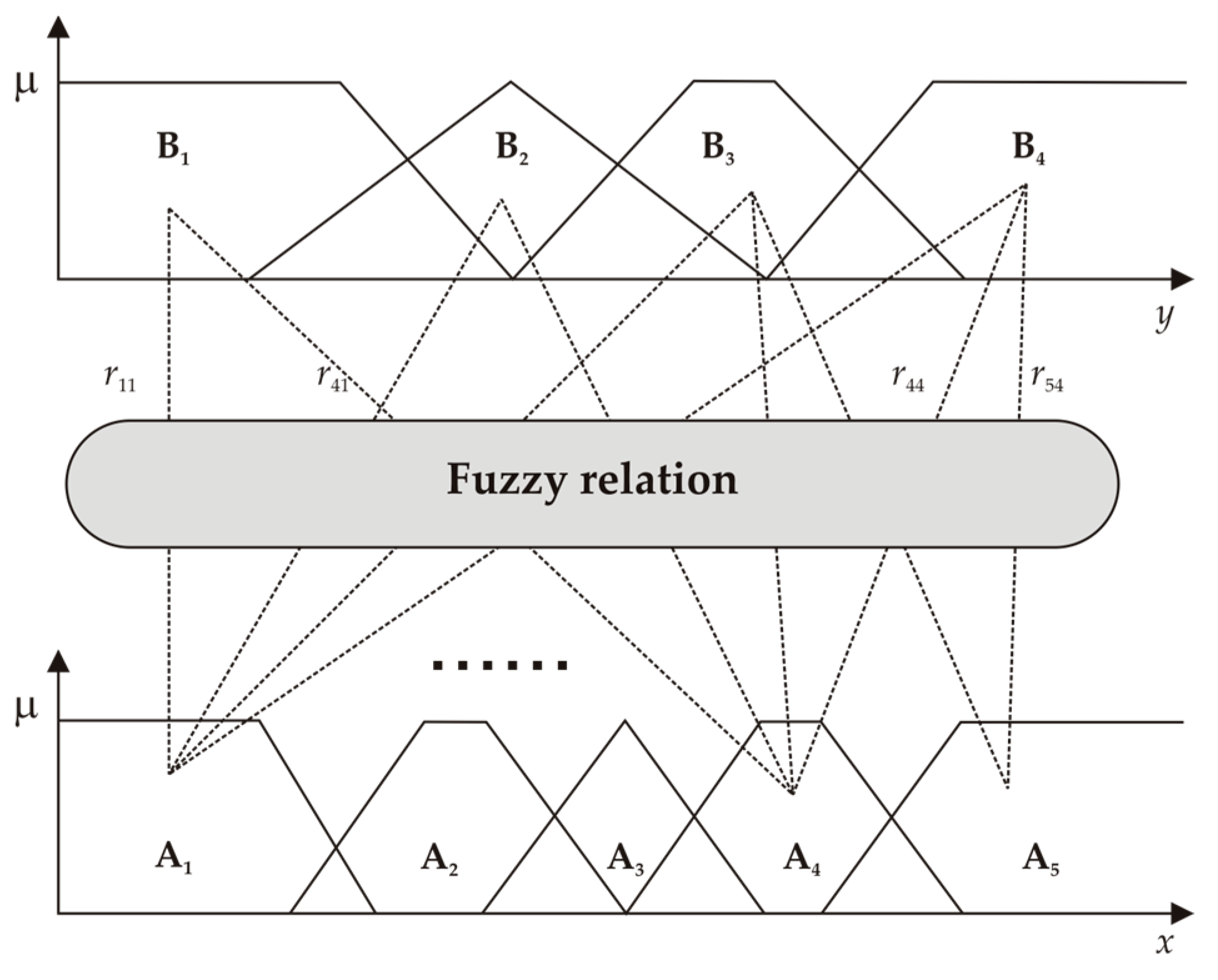
It is known as Pedrycz’s fuzzy relational models, in which the relationships between input linguistic variables A
j = {A
j,l|l = 1,2, …, N
j}) in rules and output consequences (B = {B
l|l = 1,2, …, M}) using fuzzy relations are expressed (
Figure 2). The individual elements of the relation reflect the strength of the interconnection of the fuzzy sets in it.
Let us consider the already described linguistic fuzzy model, which is built from the following fuzzy relations depicted with
r, the general formula of all rules is then:
The feature of the fuzzy model is that the fuzzy rule Formula (2) expresses an exact relation S between the activated fuzzy sets A
j of the input quantities in the premise part and the activated fuzzy set B of the output quantity in the consequent part:
In the rule consequence, all fuzzy sets of the output variable are included with waited coefficient rij. In this way, the precise setting of the fuzzy model can be made.
3. Fuzzy Logic Design
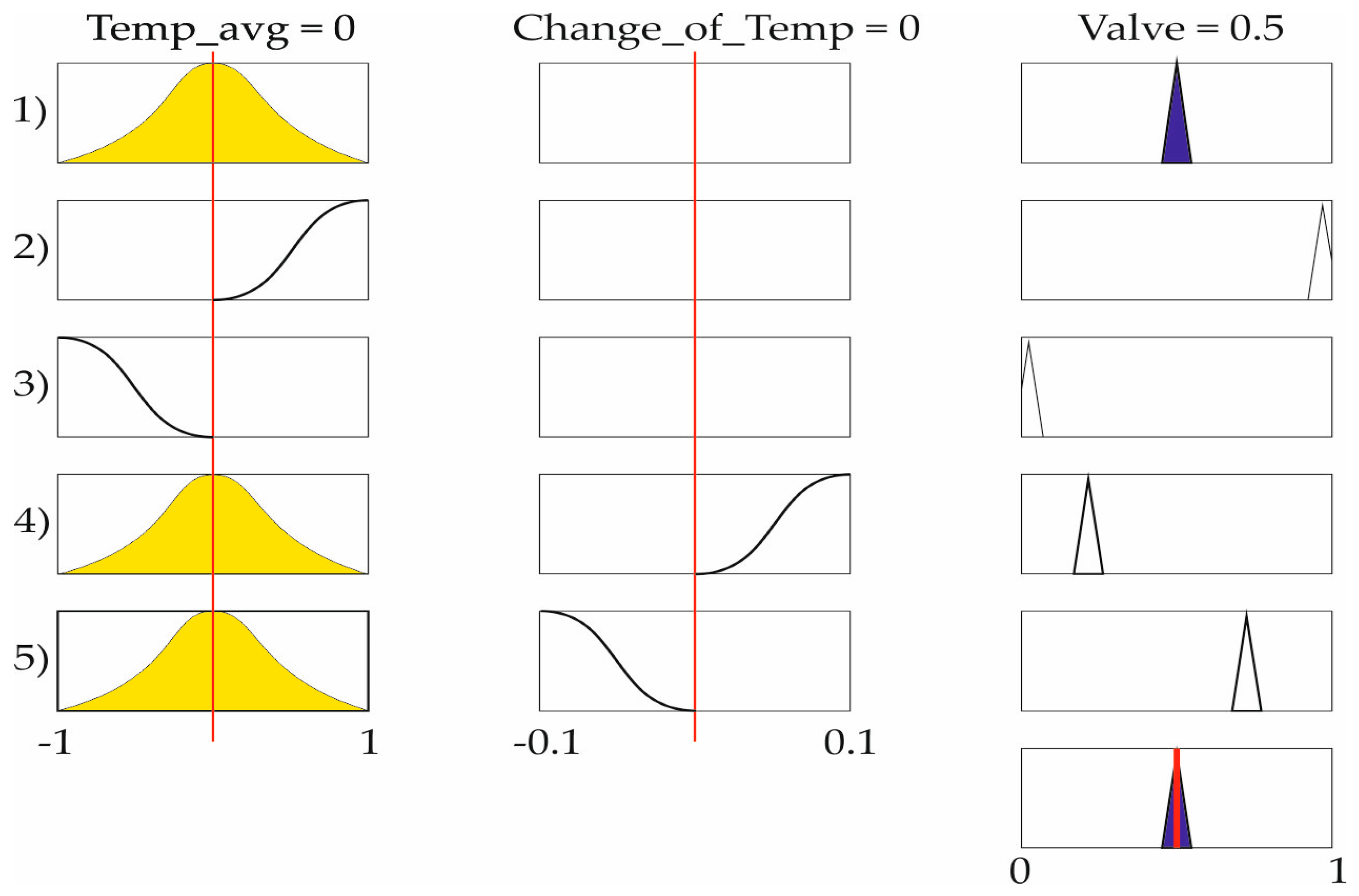
In this work, the fuzzy logic was used for control action calculation. The controller development included two inputs and one output with Mamdani inference mechanism. The system error was the first input and was calculated as a difference between the reference and the mean value of temperature—Temp_avg (
x). The second input was the difference of this error—Change_of_Temp (
). The control action was applied to the fuel control valve (
u). The Gaussian membership function (MF) for the fuzzification of the two input signals was used. The linguistic sets were as follows: “Ref”, “High”, “Low”, “Positive”, “None”, “Negative”. For the first input the MF from 1) to 5) are given with yellow. In the middle with two MF is presented the change of temperature. For the output control signal, five triangle MF (blue colour) were used, as depicted in
Figure 3.
The control signal is described with five linguistic variables: “close_fast”, “close_slow”, ”no_change”, ”open_slow”, ”open_fast”. Generally, the number of rules is determined by the product of the number of fuzzy sets of the input variables, (5).
In our case, the fuzzy logic rules had a simple construction:
The maximum number of rules is a combination of the fuzzy sets of the three variables. For the developed regulator, the number of rules is obtained experimentally. Hence, the fuzzy logic rule base consists of five rules. The variable representation occupies the normalized and universal ranges [−1;1]. The yellow color shows the so-called “activation” of the MF, as seen in
Figure 3. This is when the incoming values is within of its range. The blue color is about the activated MF of the control signal. All parameters of the developed fuzzy controller were as follows: number of the inputs—2, number of the outputs—1, number of the linguistic rules—5, number and type of the MF: for the system error and its change—3 MF, for the output—5 MF, ranges of the variables for the system error and its change the range is [−1;1], for the output the range is [0;1].
4. A Building Automation Description
Initially, BA was used widely pneumatic or air-based elements and devices. Hence, it was generally limited to controlling various aspects of the HVAC system. The control or automation of buildings may find out described with terms as: Building Automation and Control Systems (BACS), Building Control System (BCS), and/or Building Management System (BMS), Energy Management System (EMS), Smart Building (SB), etc. By the definition, one may assume that the BMS includes a control system. It can be the well-known SISO type—Single Input Single Output—hence, the system has one control loop. Then, a complex case has multi inputs and multi outputs—MIMO type. Such systems can be used to monitor, setup and control the electrical, mechanical and electromechanical devices in a facility. Thus, services can include power, heating, ventilation, air conditioning, physical access control, pumping stations, elevators and lights. At the very beginning, BA includes control of mechanical, electrical and plumbing systems. For example, the ventilation, heating and air-conditioning system is almost always controlled, including control of its various equipment such as: air handling units, boilers, fans, chillers, heat pump units, lighting, security, fire alarms, etc. Recently, the automation system is hidden, as hardware devices are mounted to equipment or underfloor or in the ceiling. The user can make some personal settings through panels or other devices. From a centralized management point of view, the BA resides as software on an operator workstation or a computer, or is available as a web view. This paper presents a model of a building heating system. It generally includes radiators, a heater of the water, average temperature calculation and outdoor temperature as a disturbance and control approach. Therefore, having single input, single output as to the temperature control loop, in our case, the system was SISO type.
Plant Model Description
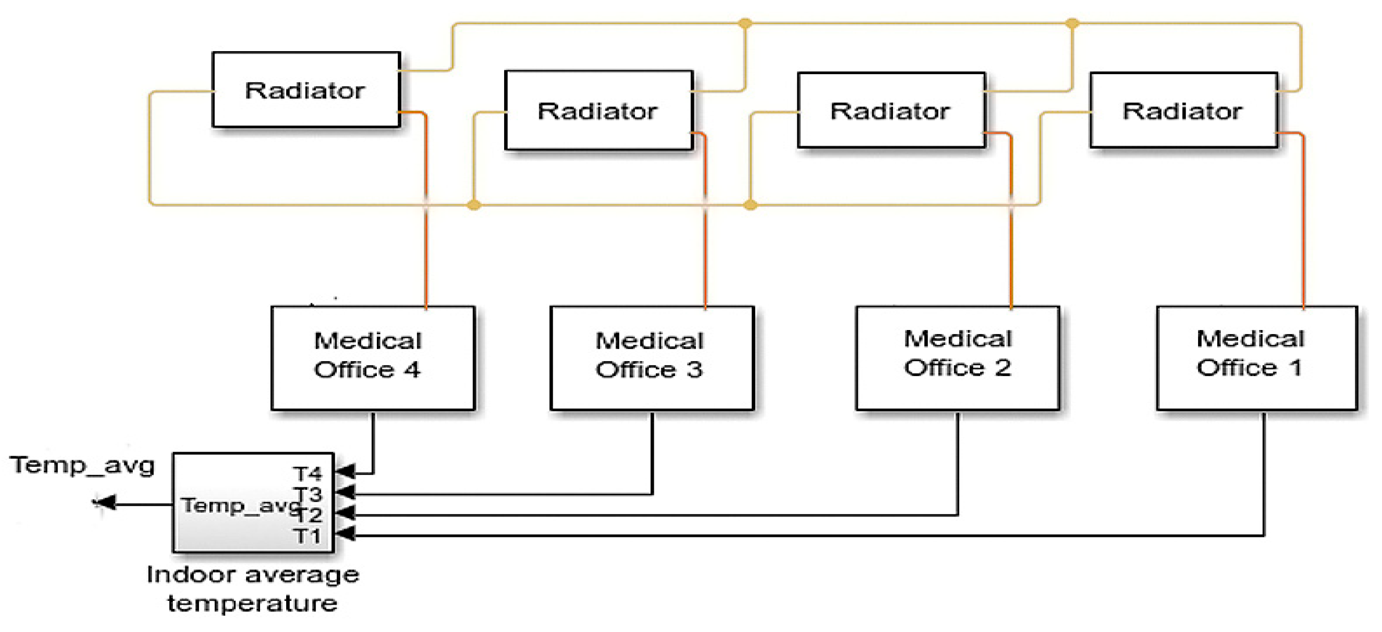
In this section, a model of the Medical Center Heating System (MCHS) is described. The overall floor view consists of four offices, as seen in
Figure 4. This model is an example of a simple building heating system. It contains a heater, a controller and a house structure with four radiators and four premises. All exchange heat with the environment through its exterior walls and roof. Each path is simulated as a combination of a thermal convection, thermal conduction and the thermal mass. It is assumed that heat is not transferred internally between rooms. They are equipped with a temperature sensor and a radiator. The mathematical equations describe air, wall thermal mass, some leakage and are considered in the simulation model, introduced by MathWorks [
4].
The blocks, which represent the rooms, are part of internal energy storage in a thermal network. The rate of temperature increase is proportional to the heat flow rate into the material and inversely proportional to the mass and specific heat of the material. Each radiator is included of a thermal network as well.
The MCHS has a heat exchanger in a thermal liquid network. It is added to the model, given in the section and is directly connected to and affects the control action, Heat is transferred to an external fluid whose flow is controlled by physical signal inputs. The heating system is assumed to be a complete oxidation of a simple hydrocarbon fuel. The fuel mass flow rate, fuel temperature, humidity ratio and air temperature are set by physical signal inputs. The controller starts pass fuel into the heating part if the overall average temperature of rooms falls below 21 °C and it stops if the temperature exceeds 25 °C.
5. Control System Design
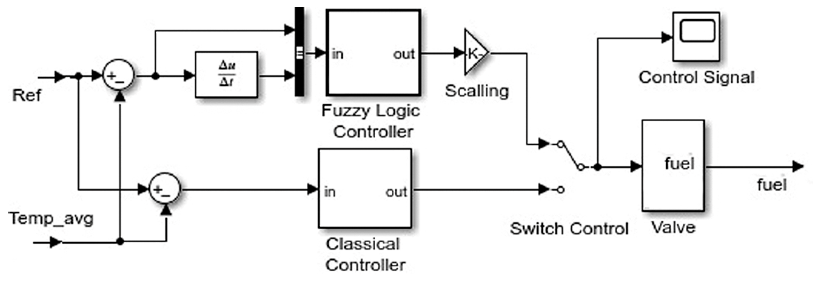
The fuzzy logic basement was used to design control strategy. The fuzzy action is developed and applied to a floor of the thermal network into medical center model. The MATLAB toolbox was used for rule base representation, which was described in the previous section. The fuzzy logic controller (FLC) block is placed in control system scheme (
Figure 5). It calculates the control action regarding to the system’s error e (6). In simulation environment, the manual switching is used to allow control changes. This allows comparative experiments about the behavior of classical and fuzzy types of control.
The goal of the controlling is to reach the predefined temperature reference value, known as an operation point. To achieve process stabilization, good response quality and reach reference the control action is applied to the actuator. The classical control law is used in all cases with low disturbances with small amplitudes and for one operating point. In the case of disturbance signals being bigger than 10% of the reference, this control strategy cannot guarantee the quality and stabilization of the process parameters no matter that it has one operating point. The outdoor temperature changes can be assumed as main disturbance for the control system loop. Actually, it is out of this acceptable mentioned range of changes. Daily amplitude of the outdoor temperature may vary between 4 °C and 20 °C. Furthermore, the transient response quality is affected by this fluctuation as well. In the present case study, the disturbances were changed between −10 °C and 15 °C. It is necessary to readjust the control parameters (for instance: proportional, differential and integration coefficients) or to implement a cascading control scheme. The heating system has constant parameters and not need more complex or adaptive control approach. In this work, it was very appropriate to apply fuzzy logic in control strategy, even than the adaptive and more complex another one. It can deal in wide range with no readjusting of the control parameters. In this work, for the controller development, the tool in MATLAB was used as an initial experimental with the MCHS model. Furthermore, the obtained results can be used to shift from simulation to real implementation of the control parameters and experience. Based on these results, if the plant has variable parameters, the combination of the fuzzy rules in a complex strategy can be created.
6. Simulation Experiments
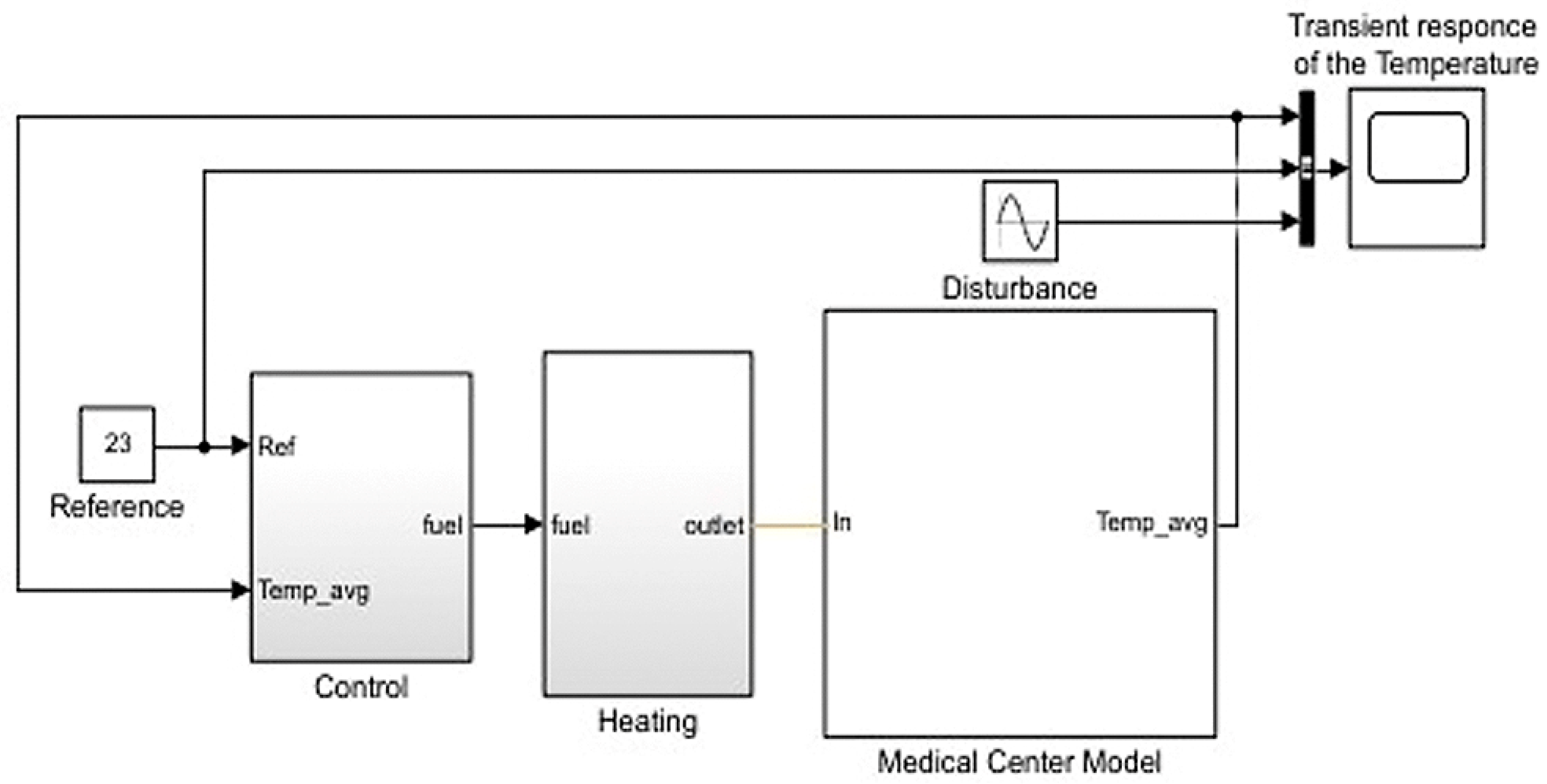
The popular MATLAB/Simulink environment for experiments was used. The block scheme of the whole MCHS model is given in
Figure 6. This was considered as a case study example to illustrate the benefits of the design paradigm. It presented three main items: a model with four rooms and radiators—multizone heating system for the medical center under consideration, heating part and control unit. It was assumed that, for each room, the heat was exchanged with environment through its exterior walls, roofs and windows and was not transmitted internally between them. The model was found in the MATLAB environment and was developed and applied fuzzy logic control to the valve as an actuator.
7. Results
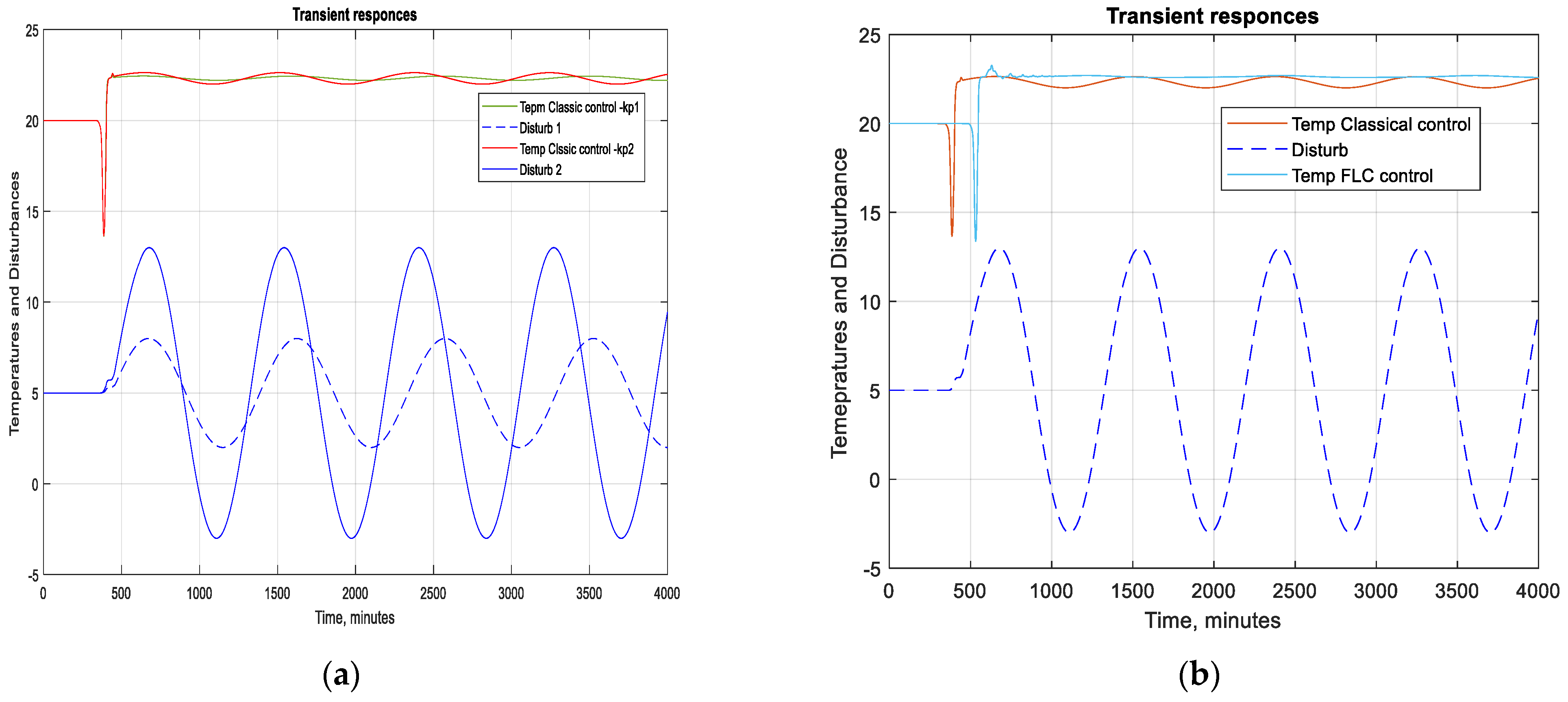
The simulation environment was used for experiments with model of the plant and control development application. Furthermore, the parameters and control strategy can be shifted to the real heating system. These responses were obtained with classical control action. The figure had four signals: reference, responses with classical control actions—red and green lines, with different proportional coefficients Kp, respectively, and two lines for disturbances with blue color below. The statement that the process needed readjusting was confirmed. Generally, the two basic algorithms used were P and PI. The different coefficients values of the conventional law were used like proportional and integral gains, respectively, Kp, Ki and integral time Ti for the experimentations. The output of the controller was changes in the response to a disturbance, because the set point was the same. The actuator of the heating system had integral behavior. Hence, the combination between control action and valve had the PI mode in close loop response. With higher values of the external temperature to keep the quality of response, the controller parameters had to be updated. The fuzzy controller can deal with the disturbance but classical one was not good enough. The proportional gain with better process quality was in the range from 0.5 to 1.
The response comparison with different control action and bigger outside temperature was made (
Figure 7a). In
Figure 7b, the blue line represents transient response with applied fuzzy action. The red line represents transient response with classical control one. It is evident that the FLC ensured better quality of the process with bigger disturbance (
Figure 8a).
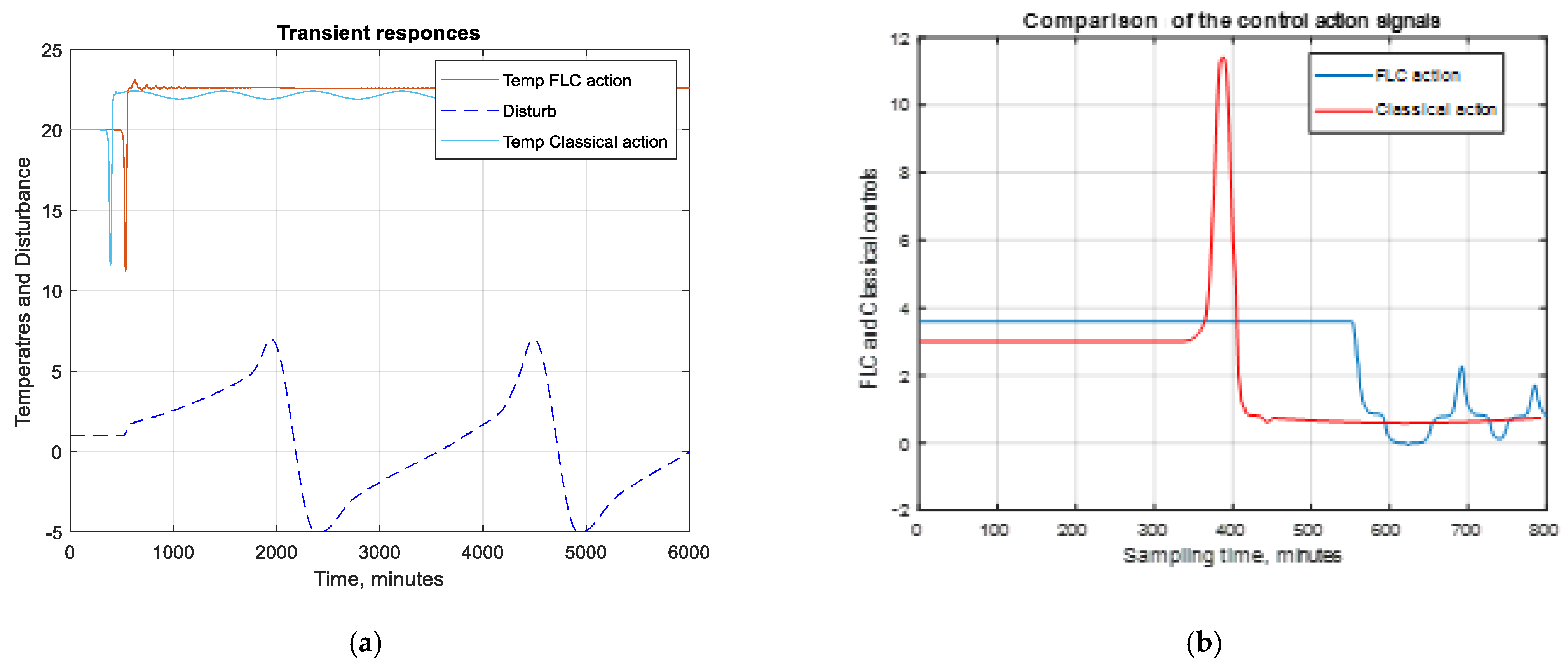
With larger amplitudes of the external temperature, the classical control laws could not stabilise the quality without readjustment. Compared to these features, the FLC control approach maintained the quality of process. This was one of the advantages of the developed strategy work. From a different point of view, the control action behavior is important. After control value calculation, by using conventional laws or fuzzy rules, the actuator has to be able to deal with it. In this work, the comparison experiment was made to show the character of the control signals (
Figure 8b). The graphic presents the control action signals. The red line depicts the conventional control behavior. It had undesired peak connected to the system error changes. In real implementation, this can damage the actuator in the heating equipment. To overcome this, there are many tuning methods, but they still need readjustments. The signal type of the FLC controller does not have such peaks. This is another advantage of the proposed control approach. The changes of the control signal regarding the system error are acceptable and applicable to the heating actuator.
8. Conclusions
The paper contained a description of the building model structures and fuzzy control strategy. The basements and the design aspects of a fuzzy logic control in the frame of classical control system manners of its realization were presented and were considered and carried out. The benefit of the work was to apply intuitive logic to the heating room model with an easy way to shift the results to a real building management system—BMS. This example showed that it can be assumed as a model of a simple building heating system. The aim of work was to describe fuzzy logic applied to the temperature control approach. The Simulink model of a widely popular building automation was used. The simulation experiments with applied fuzzy control were conducted and comparison results with conventional control law were obtained. The predefined experience can be incorporated in more complex control strategies to the plants with changeable parameters and disturbances. The work can be viewed as an intelligent control development as simple as a basement for further improvement. The simulations with applied fuzzy and classical control actions were depicted. The obtained comparison results highlighted the advantages. The model of the room heating system and simulations confirmed that the fuzzy control can deal in more wide range with no readjusting of the control parameters. The advantage was that operating range is bigger than range of classical law and be used in real building management strategy. The benefits of the work were the developed and applied fuzzy logic control approach to the model of the medical center heating system; experiment investigations in simulation environment and comparison with conventional control law.


