Proceeding Paper

Lensless Hyperspectral Phase Retrieval via Alternating Direction Method of Multipliers and Spectral Proximity Operators †

Computational Imaging Group, Faculty of Information Technology and Communication Sciences, Tampere University, 33720 Tampere, Finland
*
Author to whom correspondence should be addressed.
Presented at the International Conference on “Holography Meets Advanced Manufacturing”, Online, 20–22 February 2023.
Eng. Proc. 2023, 34(1), 19; https://doi.org/10.3390/HMAM2-14146
Published: 13 March 2023

Abstract

:
We consider the application of a recently developed hyperspectral broadband phase retrieval (HSPhR) technique for spectrally varying object and modulation phase masks at 100 spectral components. The HSPhR method utilizes advanced techniques such as Spectral Proximity Operators and ADMM to retrieve complex-domain spectral components from multiple spectral observations. These techniques filter out noisy observations and strike a balance between noisy intensity observations and their predicted counterparts, resulting in accurate retrieval of the broadband hyperspectral phase even for low signal-to-noise ratio components. Both simulation and physical experiments have confirmed the effectiveness of this approach.

1. Introduction

Hyperspectral imaging (HSI) is a well-known technique for spectral observations. It is used in various applications, e.g., earth surface remote sensing [1], and medical and bio-medical diagnostics [2]. HSI retrieves information based on images obtained across a wide spectrum range with hundreds to thousands of spectral channels. These images are stacked in 3D cubes, where the first two dimensions are spatial coordinates, and the third dimension is a spectral channel, represented by either wavenumber or wavelength.
Phase HSI is a special class of HSI where images of interest are complex-valued, and both phase and amplitude are visualized. It is a promising technique because the amount of retrieved information is doubled compared to real-valued HSI. It goes directly from the nature of complex-domain imaging, where each image is complex-valued with phase and amplitude. Phase brings information about the light delay refracted/transmitted from/through an object. This delay might be recalculated into valuable information, e.g., dry mass [3], refractive index [4], or thickness [5].
Recently, HS digital holography has been developed, which, additionally to conventional holography, is able to recover spectrally resolved phase/amplitude information (e.g., Refs. [6,7]). In our previous papers [8,9,10], the phase HSI formulation was done for the observation model provided that the parametric model of the object is known and has been used for phase delay recalculation between spectral channels. As a result, the HS absolute phases of the object are reconstructed. In the papers [8,9,10], we used an observation model where separate diffraction patterns were registered for separate wavelengths and masks. More close papers are [11,12], where we based our algorithms on the Fourier spectroscopy. In Ref. [11], we used the model for the object with the connection between the spectral phases through the thickness. However, the proposed new model for phase HSI is different from the Fourier spectroscopy approach as it does not use any instruments for spectral analysis, such as the harmonic reference beams and precise scanning phase delay stages [6,7]. The spectral resolution for the considered approach is based on the diversity of spectral properties of the image formation operators and masks [13].
In this paper, we consider applying the developed in Ref. [13] HS phase retrieval algorithm for an object whose phase and amplitude are characterized on a spectrum with 100 spectral components in simulation and physical experiments.

2. Hyperspectral Phase Imaging

In this section, we briefly describe the HS phase retrieval algorithm developed in Ref. [13]; for a detailed derivation of the solutions, please follow the pioneering paper [13].
To solve the lensless phase retrieval problem, we utilize random phase masks M t , k C T × N which, along with propagation operator A t , k , encode information about an object U o , k into the observations Y t [14]:
Y t = k K | A t , k ( M t , k U o , k ) | 2 ,   t = 1 , , T ,
where Y t R N , and A t , k C K × N is an image formation operator modeling propagation of 2D object images from the object plane to the sensor, and ‘∘’ stands for the element-by-element product of two vectors. For the object of interest, it is the vector U o , k C K × N , N = n m , where n and m are the width and height of 2D image; k stays for the spectral variable.The HS phase retrieval is a reconstruction of a complex-valued object U o , k C K × N ,   k K , from these intensity measurements Y t (1). For essential noisy observations with additive noise ε t , observations Y t are complemented by noise ε t :
Z t = Y t + ε t ,   t T .
The total intensity measurement Y t R N is a sum of intensities from all spectral components K, which means that spectral information is severely mixed in the observations.

2.1. HS Phase Retrieval Solution (HSPhR)

Traditionally, the solution U o , k is found by measuring the mismatch between the observations and the prediction of the intensities of U t , k summarized over the spectral interval. We realize it through a neg-log-likelihood of the observed { Z t } , t T , as l ( { Z t } , k K | U t , k | 2 ) , where U t , k are the complex-valued object wavefronts at the sensor plane calculated as U t , k = A t , k ( M t , k U o , k ) . In the following text, the curly brackets signify a group of variables. We use an unconstrained maximum likelihood optimization to reconstruct the object 3D cube { U o , k } ,   k K , from the criterion of the form:
min { U o , k } l ( { Z t } , k K | A t , k ( M t , k U o , k ) | 2 ) + f r e g ( { U o , k } ) ,
where a second summand is an object prior. We solve it by alternating direction method of multipliers (ADMM) [15,16,17,18]. Next, Equation (3) is reformulated as a constrained optimization:
min { U t , k ,   U o , k } l ( { Z t } , k K | U t , k | 2 ) + f r e g ( { U o , k } ) , w . s . t .   U t , k = A t , k ( M t , k U o , k ) .
We resolve (4) by the unconstrained formulation with the parameter γ > 0 :
J = l ( Z t , k | U t , k | 2 ) + 1 γ t , k | | U t , k A t , k ( M t , k U o , k ) | | 2 2 + f r e g ( { U o , k } ) .
The second summand is the quadratic penalty for the difference between A t , k ( M t , k U o , k ) and the splitting U t , k . In the optimization of (5), U t , k A t , k ( M t , k U o , k ) as γ 0 . The minimization algorithm iterates min { U t , k } J with given U o , k and min { U o , k } J with given U t , k :
U t , k ( s + 1 ) = arg min U t , k ( l ( Z t , k | U t , k | 2 ) + 1 γ t , k | | U t , k A t , k ( M t , k U o , k ) ( s ) | | 2 2 ) ,
U o , k ( s + 1 ) = arg min U o , k ( f r e g ( { U o , k } ) + 1 γ t , k | | U t , k ( s + 1 ) A t , k ( M t , k U o , k ) | | 2 2 ) .
For the iterative solution of (6) and (7), we introduce the Lagrangian variables Λ t , k [19]:
U t , k ( s + 1 ) = arg min U t , k J ( { U t , k , U o , k ( s ) , Λ t , k ( s ) } ) , U o , k ( s + 1 ) = arg min U o , k J ( { U t , k ( s + 1 ) , U o , k , Λ t , k ( s ) } ) , Λ t , k ( s + 1 ) = Λ t , k ( s ) 1 γ ( U t , k ( s + 1 ) A t , k ( M t , k U o , k ( s + 1 ) ) ,
where s is the iterative variable.
Minimizing (7) on U o , k , we replace the regularization term f r e g ( { U o , k , k K } ) with noise suppression in { U o , k , k K } . It is done by Complex Cube Filter (CCF) [20], developed specifically for 3D hyperspectral complex-domain images. Then, the solution for U o , k is of the form
U o , k = t A t , k H M t , k H ( U t , k Λ t , k ) t A t , k H A t , k + r e g ,
where the regularization parameter r e g > 0 is included if t A t , k H A t , k is singular or ill-conditioned.
Minimization on U t , k (6) depends on the noise type in observations { Z t } . We consider two types of noise: Poisson and Gaussian. For the Gaussian noise, the loss function is
J = 1 σ 2 t | | Z t k | U t , k | 2 | | 2 2 + 1 γ t , k | | U t , k A t , k ( M t , k U o , k ) Λ t , k | | 2 2 .
And for the Poisson noise, considering its multiplicative nature, the loss function is the following.
J = t χ k | U t , k | 2 Z t log ( k | U t , k | 2 χ ) + + 1 γ t , k | | U t , k A t , k ( M t , k U o , k ) Λ t , k | | 2 2 + f r e g ( { U o , k } k K ) ,
where χ > 0 is a scaling parameter for photon flow, it is proportional to the camera exposure time and defines the noise level of a signal. The signal-to-noise ratio E { Z t } 2 / v a r { Z t } = Y t χ takes larger values for larger χ .
To minimize min { U t , k } J , we need to calculate the derivatives with respect to U t , k * and then evaluate the necessary minimum conditions by setting the derivative to zero. This process involves solving a set of complex-valued cubic equations for Gaussian observations (10):
2 σ 2 ( k K | U t , k | 2 Z t ) + 1 γ U t , k = 1 γ ( A t , k ( M t , k U o , k ) + Λ t , k ) .
With a solution in the form
U ^ t , k = A t , k ( M t , k U o , k ) + Λ t , k 1 + 2 γ σ 2 ( k K | U ^ t , k | 2 Z t ) .
For Poisson observations (11), minimization leads to the set of non-linear equations with respect to U t , k :
χ Z t k K | U t , k | 2 + 1 γ U t , k = 1 γ ( A t , k ( M t , k U o , k ) + Λ t , k ) .
With a solution in the form
U ^ t , k = A t , k ( M t , k U o , k ) + Λ t , k 1 + γ χ + γ Z t k K | U t , k | 2 ,   k K .
The solutions for min { U t , k } J can be interpreted as spectral proximity operators (SPO), generated by minimizing the likelihood items with a quadratic penalty, for both Gaussian and Poisson:
U ^ t , k = p r o x f γ ( A t , k ( M t , k U o , k ) + Λ t , k ) ,
where f stays for the minus-log-likelihood part of J and γ > 0 is a parameter.
These operators solve two problems: First, they extract and separate complex-valued spectral components U t , k from the real-valued observations Z t , in which these components are mixed into the total intensity of the signal. Thus, it provides the spectral analysis of the signals. Second, the noisy observations Z t are filtered with the power controlled by the parameter γ compromising Z t and the power of the predicted signal A t , k ( M t , k U o , k ) at the sensor plane. For a detailed derivation of the solutions, follow the pioneering paper [13].

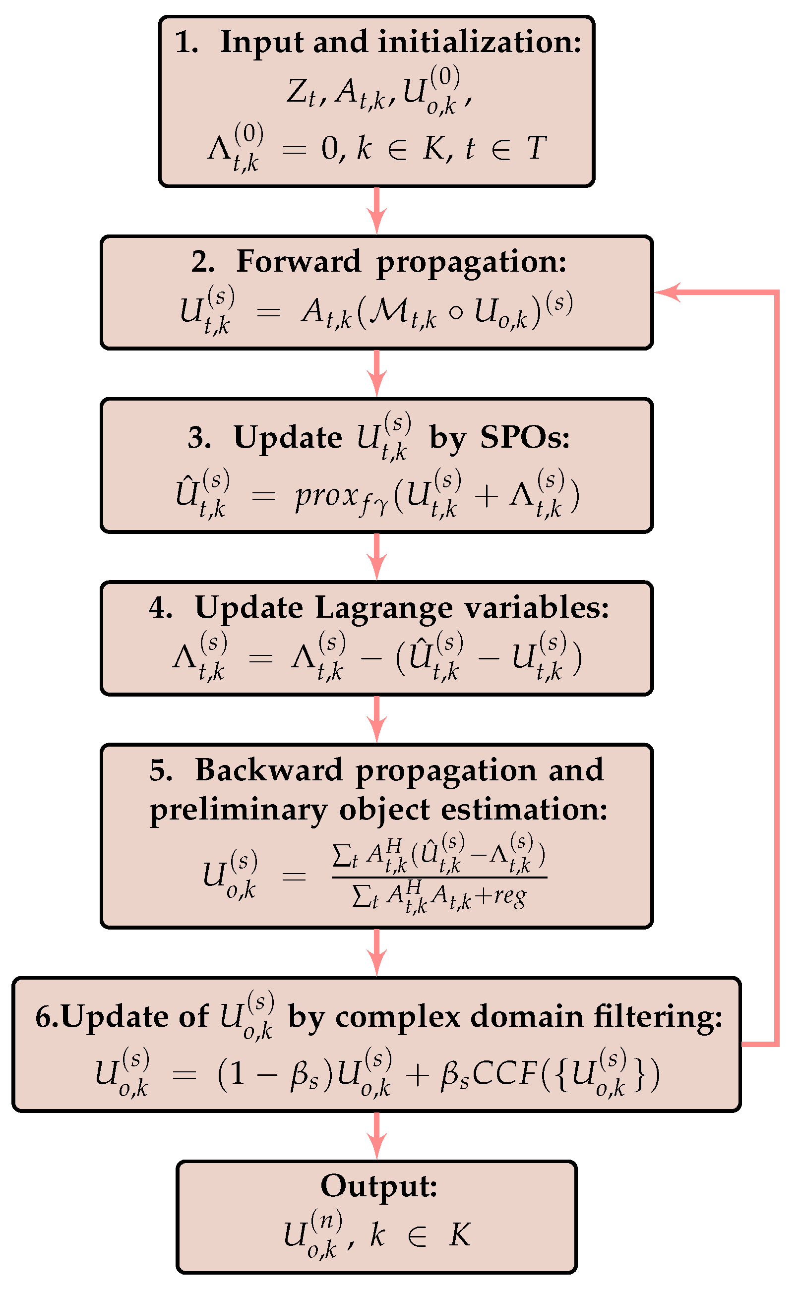
2.2. Developed Algorithm

A block scheme of the algorithm is shown in Figure 1. Complex domain initialization (Step 1) is required for the considered spectral domain k K . In our experiments, we make a 2D random white-noise Gaussian distribution for phase and a uniform 2D positive distribution on (0,1] for amplitude, which are independent for each k. The Lagrange multipliers are initialized by zero values, Λ t , k = 0 . The forward propagation is realized through the angular spectrum approach and produced for all k K and t T (Step 2). The update of the wavefront at the sensor plane (Step 3) is produced by the proximal operators (SPO). For the Gaussian observations, this operator is defined by (13), and for the Poisson observations—by (15). Calculating k K | U ^ t , k | 2 requires solving the polynomial equations, cubic or quadratic, for the Gaussian and Poisson cases, respectively. In Step 4, the Lagrange variables are updated. The backward propagation of the wavefront from the sensor plane to the object plane is combined with an update of the spectral object estimate in Step 5. The sparsity-based regularization by Complex Cube Filter (CCF) [20] is relaxed by the weight-parameter 0 < β < 1 at Step 6. The iteration number is fixed to n.

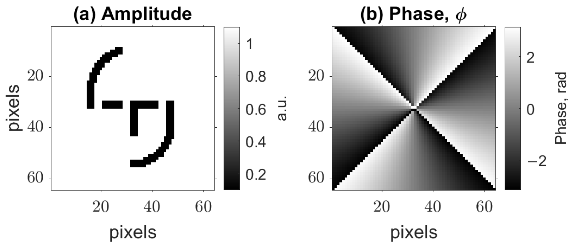
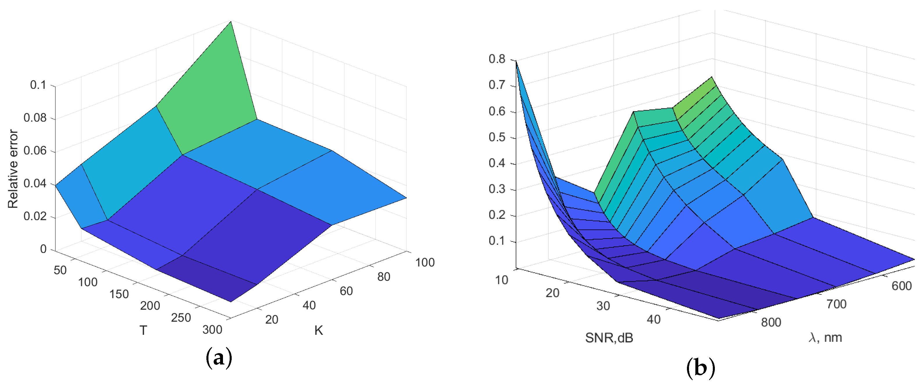
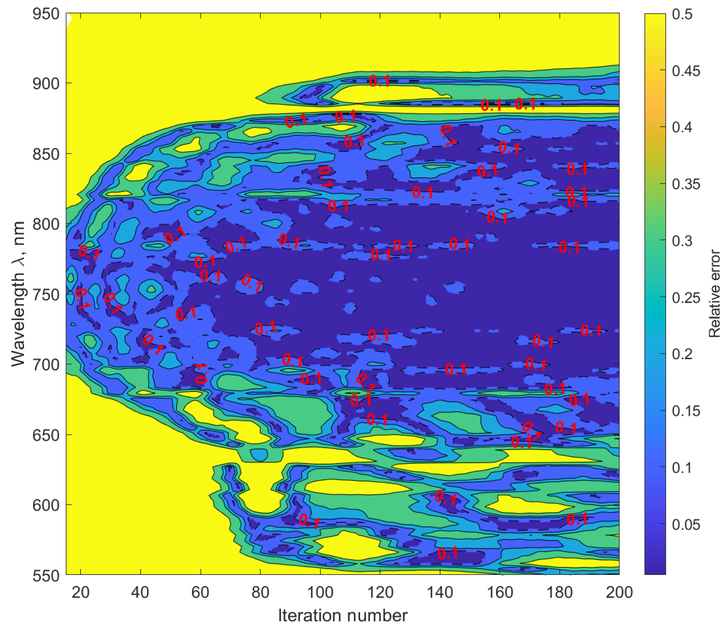
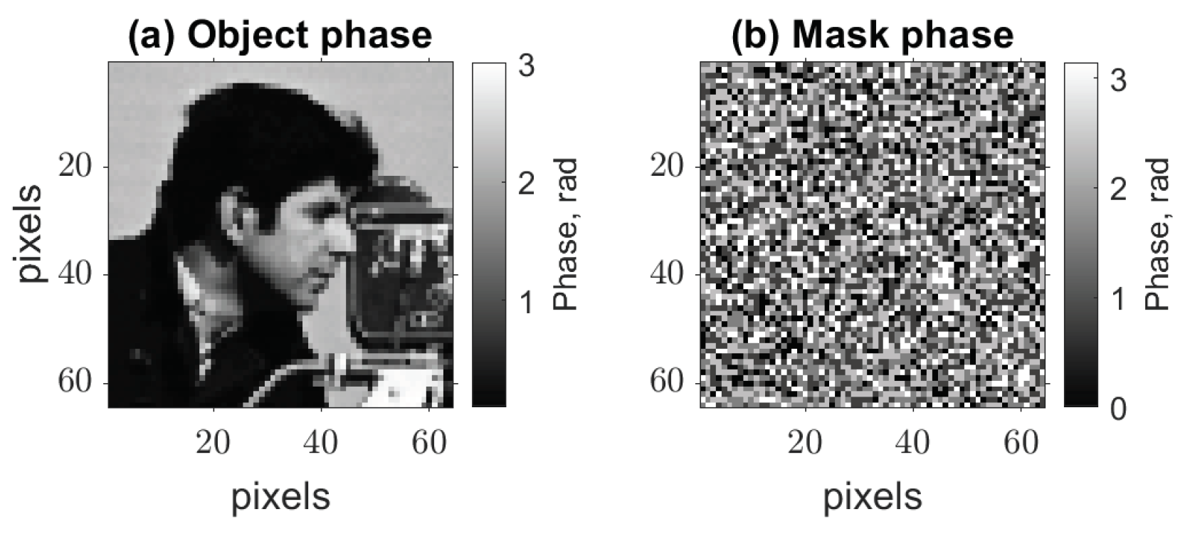
3. Numerical Experiments

Simulation experiments are produced for the complex-valued wavefronts obtained from the propagation of an HS light beam through a thin transparent object. We define the phase delay of the object as:
φ k = ϕ · λ 1 λ k n λ k 1 n λ 1 1 , k [ 1 : K ]
where λ k is a wavelength of the wavefront ( Λ = 550 950 nm) with total number of wavelengths K = 100 , ϕ is a basic phase distribution, and n λ k is the refractive index of the optical material of the object. We took the phase distribution for ϕ as a vortex beam phase in the range of [ π , π ] and amplitude as a logo of Tampere University in the range of [ 0 , 1 ] , see Figure 2. Spectral amplitude dependence is modeled in accordance with the spectrum of a supercontinuum white laser (see Section 4), providing a non-uniform spectral distribution. This non-uniformity strongly complicates the reconstruction process because of low-intensity spectral components.
It is of particular interest to investigate the dependence between the accuracy of the algorithm and the wavelength number, represented by K, as well as the number of observations denoted by T. To evaluate the accuracy of the complex-valued reconstruction, we use the relative error criterion [21]:
E R R O R r e l = min φ [ 0 , 2 π ) | | x ^ exp ( j φ ) x | | 2 2 | | x | | 2 2 ,
where x and x ^ are the true signal and its estimate. If E R R O R r e l is less than 0.1 the quality of imaging is high. We calculate E R R O R r e l for K = [ 6 , 20 , 60 , 100 ] and T = [ 18 , 60 , 180 , 300 ] . The wavelengths for the varying K are distributed uniformly covering the spectral interval [ 550 , 950 ] nm. The number of iterations is fixed to n = 200 . The relative errors E R R O R r e l obtained in these experiments are shown in Figure 3a. It is shown that E R R O R r e l is low for the high number of masks, T, and for high-quality imaging, the needed number of masks equals the doubled number of wavelengths. Therefore, for the simulation case of K = 100 we took T = 200 .
In Figure 3b, we show E R R O R r e l dependence on the noise level in the observations, which is characterized by the signal-to-noise ratio (SNR) in dB and on wavelength with K = 6 and T = 18 . It is seen that for noise levels with SNR bigger than 30 dB E R R O R r e l is low and indicates high-quality imaging. It is interesting to note that for high noise levels (SNR < 30 dB) the shape of E R R O R r e l corresponds to the inverted spectral distribution of the modeled illumination: the spectral components with higher values (middle of the spectrum) provide lower E R R O R r e l than the spectral components with low values.
In Figure 4, we show a contour E R R O R r e l map for the HSPhR algorithm for all spectral components (Y-axis) during iterative calculations (X-axis for iteration number). High-quality imaging regions ( E R R O R r e l < 0.1 ) are dark blue on the map with signed contours ‘0.1’. At first iterations, high-quality imaging appears at only high-intensity spectral components, but with the growing number of iterations, high-quality spreads to low-intensity spectral components. Similar behavior for the spectrally dependent object was demonstrated in Ref. [20], where the developed filter CCF retrieved data from extremely noisy spectral components. Therefore, it is an illustration of the computational overcoming of Fellgett’s disadvantage [22] typical for HS observations.
The corresponding reconstruction results after the last iteration ( n = 200 ) are presented in Figure 5, where object phase and amplitude are spectrally resolved and correspond to the modeled object from Figure 2.

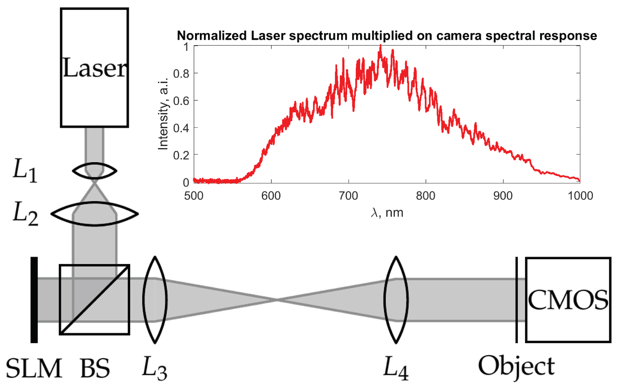
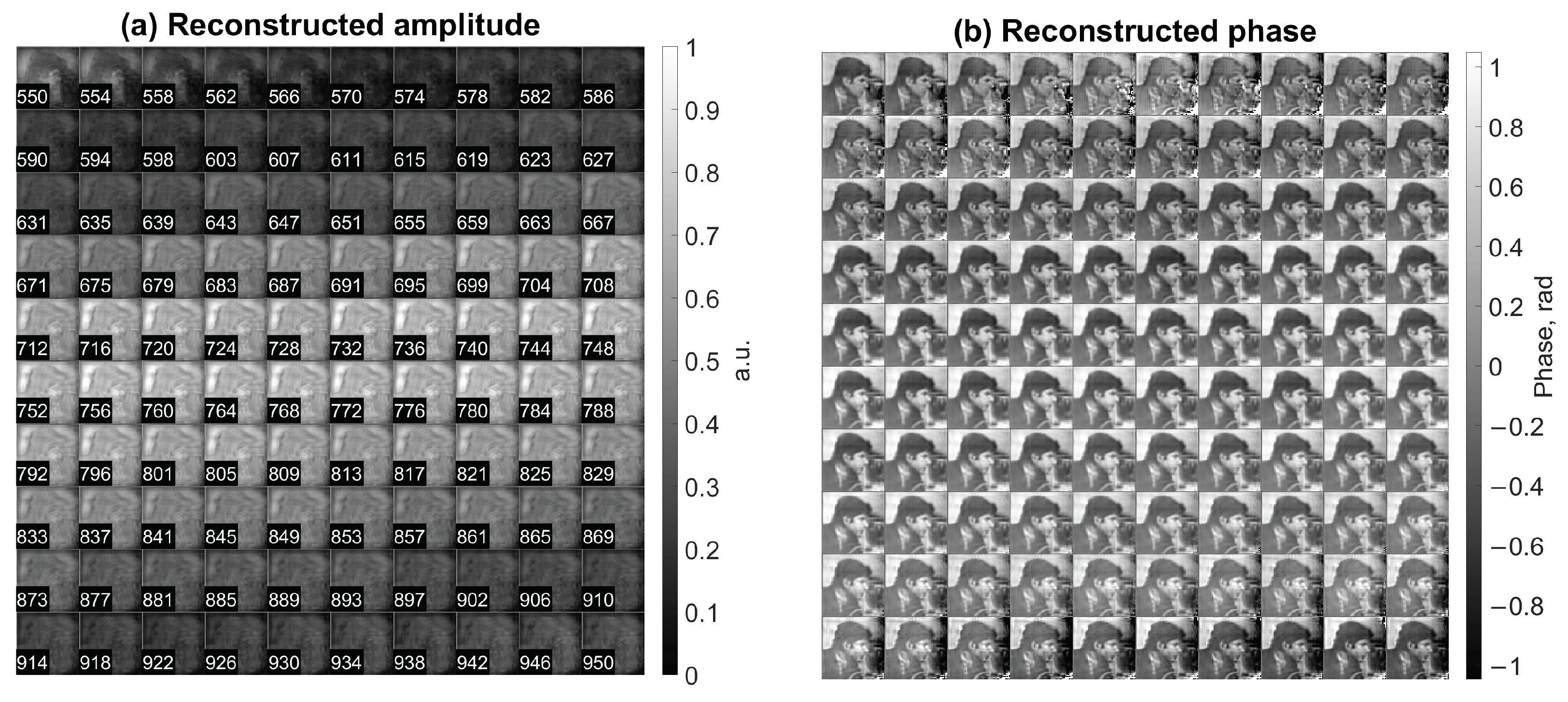
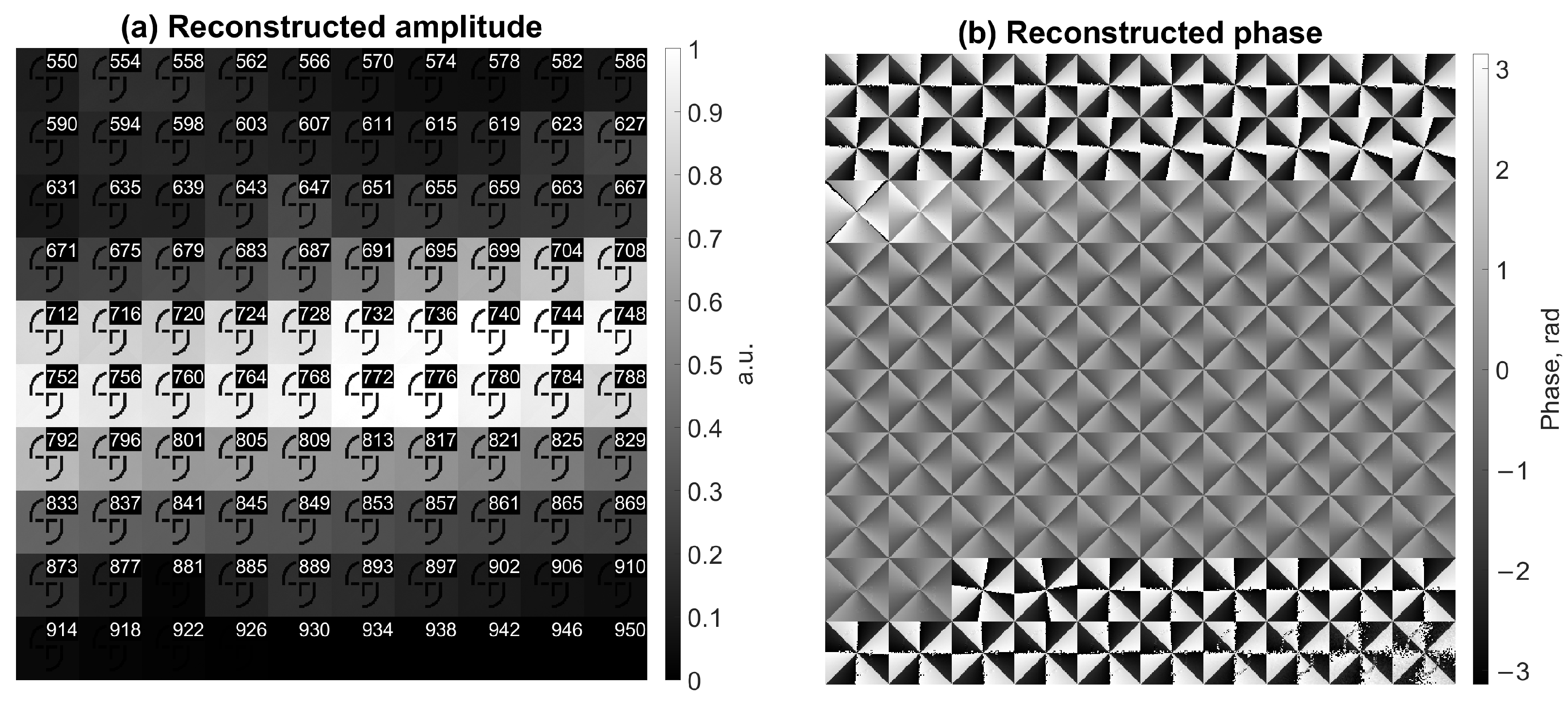
4. Experimental Validation

For the experimental validation, we used a setup with a phase-only spatial light modulator (SLM) and supercontinuum laser source, see Figure 6. A sum of the object U o , k and masks M t , k was imaged on SLM, and projected to the ‘Object’ plane by achromatic lenses ‘ L 3 ’ and ‘ L 4 ’. The light wavefront then propagates freely on distance d = 2.2 mm from the ‘Object’ plane to ‘CMOS’, where it is registered as a noisy intensity distribution, Z t , with t [ 1 , T ] . According to the simulation results, the mask spatial distribution was modeled as piecewise invariant random with equal probabilities taking one of the following five values [ 0 , 1 , 0 , 0.25 , 0.75 ] · p i , for the λ = 520 nm. The object was taken as an image of a cameraman with 64 × 64 pixels, and phase images of a single randomly picked mask and object are in Figure 7. SLM is the Holoeye phase-only GAEA-2-vis panel, resolution 4160 × 2464, pixel size 3.74 μm. The laser is YSL photonics CS-5 with Λ = 470 ÷ 2400 nm. To work in the spectral range of the sensor, we limit the laser’s spectral bandwidth to the Λ = 470 ÷ 1000 nm range by a bandpass filter. The camera is a monochrome Blackfly S board with the matrix Sony IMX264, 3.45 μm pixels, and 2448 × 2048 pixels.
The reconstruction results are presented in Figure 8, which we made from T = 300 observations and for K = 100 wavelengths. The number of observations is taken T = 300 to overcome noise problems since the estimated [23] SNR of observations equals 34 dB, which is close to the lower limit of HSPhR, estimated in the simulations. Reconstructed amplitude intensities correspond to the spectral distribution of the used laser with a maximum at λ = 750 nm, and phase images correspond to the given cameraman image. Image quality varies from low to high with respect to the intensity distribution of spectral components.

5. Conclusions

We have considered an application of an approach for hyperspectral phase retrieval that utilizes modulation phase masks for the reconstruction of a spectrally variable object with 100 spectrally dependent components. The approach which is based on a complex domain version of the ADMM method and spectral proximity operators successfully solved phase retrieval problem in the considered scenario. The proposed technique is able to retrieve complex-domain spectral components of an object from noisy observations and filter out noise by compromising between noisy intensity observations and their predicted counterparts. In the algorithm, we do not use traditional phase retrieval constraints, e.g., known aperture or phase connection among spectral components through the object thickness. With the mask imaged on a transmissive spatial light modulator, the proposed optical implementation allows a simple lensless configuration, which is significantly simpler than traditional hyperspectral approaches, as interferometry and holographic imaging. The proposed approach could potentially be useful in various applications, such as biomedical imaging, remote sensing, and materials science.

Author Contributions

I.S. developed the algorithm, conceived and designed the experiments; V.K. developed the approach and algorithm; K.E. supervised the project. All authors have read and agreed to the published version of the manuscript.

Funding

I.S. was supported by the Academy of Finland (project no. 336357, PROFI 6—TAU Imaging Research Platform).

Institutional Review Board Statement

Not applicable.

Informed Consent Statement

Not applicable.

Data Availability Statement

Data are available on request.

Conflicts of Interest

The authors declare no conflict of interest.

Abbreviations

The following abbreviations are used in this manuscript:
BSBeam Splitter
CMOSComplementary Metal–Oxide–Semiconductor
CCFComplex Cube Filter
HSIHyperSpectral Imaging
HSPhRHyperSpectral Phase Retrieval
HSDHHyperSpectral Digital Holography
SPOSpectral Proximity Operator
SNRSignal-to-Noise Ratio

References

  1. Gao, B.C.; Davis, C.; Goetz, A. A review of atmospheric correction techniques for hyperspectral remote sensing of land surfaces and ocean color. In Proceedings of the 2006 IEEE International Symposium on Geoscience and Remote Sensing, Denver, CO, USA, 31 July–4 August 2006; IEEE: New York, NY, USA, 2006; pp. 1979–1981. [Google Scholar]
  2. Calin, M.A.; Parasca, S.V.; Savastru, D.; Manea, D. Hyperspectral imaging in the medical field: Present and future. Appl. Spectrosc. Rev. 2014, 49, 435–447. [Google Scholar] [CrossRef]
  3. Ghenim, L.; Allier, C.; Obeid, P.; Hervé, L.; Fortin, J.Y.; Balakirev, M.; Gidrol, X. A new ultradian rhythm in mammalian cell dry mass observed by holography. Sci. Rep. 2021, 11, 1290. [Google Scholar] [CrossRef] [PubMed]
  4. Belashov, A.V.; Zhikhoreva, A.A.; Bespalov, V.G.; Novik, V.I.; Zhilinskaya, N.T.; Semenova, I.V.; Vasyutinskii, O.S. Refractive index distributions in dehydrated cells of human oral cavity epithelium. J. Opt. Soc. Am. B 2017, 34, 2538–2543. [Google Scholar] [CrossRef]
  5. Cazac, V.; Meshalkin, A.; Achimova, E.; Abashkin, V.; Katkovnik, V.; Shevkunov, I.; Claus, D.; Pedrini, G. Surface relief and refractive index gratings patterned in chalcogenide glasses and studied by off-axis digital holography. Appl. Opt. 2018, 57, 507. [Google Scholar] [CrossRef] [PubMed]
  6. Kalenkov, S.G.; Kalenkov, G.S.; Shtanko, A.E. Hyperspectral holography: An alternative application of the Fourier transform spectrometer. J. Opt. Soc. Am. B 2017, 34, B49. [Google Scholar] [CrossRef]
  7. Claus, D.; Pedrini, G.; Buchta, D.; Osten, W. Accuracy enhanced and synthetic wavelength adjustable optical metrology via spectrally resolved digital holography. J. Opt. Soc. Am. A Opt. Image Sci. Vis. 2018, 35, 546–552. [Google Scholar] [CrossRef] [PubMed]
  8. Katkovnik, V.; Egiazarian, K. Multi-Frequency Phase Retrieval from Noisy Data. In Proceedings of the 2018 26th European Signal Processing Conference (EUSIPCO), Rome, Italy, 3–7 September 2018; IEEE: New York, NY, USA, 2018; pp. 2200–2204. [Google Scholar] [CrossRef]
  9. Katkovnik, V.; Shevkunov, I.; Petrov, N.V.; Eguiazarian, K. Multiwavelength absolute phase retrieval from noisy diffractive patterns: Wavelength multiplexing algorithm. Appl. Sci. 2018, 8, 719. [Google Scholar] [CrossRef]
  10. Katkovnik, V.; Shevkunov, I.; Petrov, N.V.; Egiazarian, K. Multiwavelength surface contouring from phase-coded noisy diffraction patterns: Wavelength-division optical setup. Opt. Eng. 2018, 57, 1. [Google Scholar] [CrossRef]
  11. Shevkunov, I.; Katkovnik, V.; Egiazarian, K. Lensless hyperspectral phase imaging in a self-reference setup based on Fourier transform spectroscopy and noise suppression. Opt. Express 2020, 28, 17944. [Google Scholar] [CrossRef] [PubMed]
  12. Katkovnik, V.; Shevkunov, I.; Egiazarian, K. Broadband Hyperspectral Phase Retrieval From Noisy Data. In Proceedings of the 2020 IEEE International Conference on Image Processing (ICIP), Abu Dhabi, United Arab Emirates, 25–28 October 2020; IEEE: New York, NY, USA, 2020; pp. 3154–3158. [Google Scholar] [CrossRef]
  13. Katkovnik, V.; Shevkunov, I.; Egiazarian, K. ADMM and spectral proximity operators in hyperspectral broadband phase retrieval for quantitative phase imaging. Signal Process. 2023, 210, 109095. [Google Scholar] [CrossRef]
  14. Katkovnik, V.; Shevkunov, I.; Petrov, N.N.V.; Egiazarian, K. Computational wavelength resolution for in-line lensless holography: Phase-coded diffraction patterns and wavefront group-sparsity. Proc. SPIE 2017, 10335, 1033509. [Google Scholar] [CrossRef]
  15. Hestenes, M.R. Multiplier and gradient methods. J. Optim. Theory Appl. 1969, 4, 303–320. [Google Scholar] [CrossRef]
  16. Eckstein, J.; Bertsekas, D.P. On the Douglas—Rachford splitting method and the proximal point algorithm for maximal monotone operators. Math. Program. 1992, 55, 293–318. [Google Scholar] [CrossRef]
  17. Afonso, M.V.; Bioucas-Dias, J.M.; Figueiredo, M.A.T. Fast Image Recovery Using Variable Splitting and Constrained Optimization. IEEE Trans. Image Process. 2010, 19, 2345–2356. [Google Scholar] [CrossRef] [PubMed]
  18. Afonso, M.V.; Bioucas-Dias, J.M.; Figueiredo, M.A.T. An Augmented Lagrangian Approach to the Constrained Optimization Formulation of Imaging Inverse Problems. IEEE Trans. Image Process. 2011, 20, 681–695. [Google Scholar] [CrossRef] [PubMed]
  19. Li, L.; Wang, X.; Wang, G. Alternating Direction Method of Multipliers for Separable Convex Optimization of Real Functions in Complex Variables. Math. Probl. Eng. 2015, 2015, 104531. [Google Scholar] [CrossRef]
  20. Shevkunov, I.; Katkovnik, V.; Claus, D.; Pedrini, G.; Petrov, N.V.; Egiazarian, K. Hyperspectral phase imaging based on denoising in complex-valued eigensubspace. Opt. Lasers Eng. 2020, 127, 1–9. [Google Scholar] [CrossRef]
  21. Candes, E.; Wakin, M. An Introduction To Compressive Sampling. IEEE Signal Process. Mag. 2008, 25, 21–30. [Google Scholar] [CrossRef]
  22. Fellgett, P.B. On the Ultimate Sensitivity and Practical Performance of Radiation Detectors. J. Opt. Soc. Am. 1949, 39, 970–976. [Google Scholar] [CrossRef] [PubMed]
  23. Mäkitalo, M.; Foi, A. Noise Parameter Mismatch in Variance Stabilization, With an Application to Poisson–Gaussian Noise Estimation. IEEE Trans. Image Process. 2014, 23, 5348–5359. [Google Scholar] [CrossRef]
Figure 1. HSPhR algorithm. The total number of iterations is n.
Engproc 34 00019 g001
Figure 2. Modeled amplitude and basic phase ϕ of the HS object.
Engproc 34 00019 g002
Figure 3. HSPhR reconstruction relative error maps. (a) Mean relative errors depending on the number of masks, T, and the number of wavelengths, K. A number of iterations n = 200 , SNR = 54 dB. (b) Dependence of relative errors on the SNR and wavelength.
Engproc 34 00019 g003
Figure 4. Contour E R R O R r e l map for HSPhR reconstruction. K = 100 , T = 200 , SNR = 54 dB. Dark blue regions correspond to high-quality imaging.
Engproc 34 00019 g004
Figure 5. Reconstructed amplitudes (a) and phases (b) of the object in simulations. Reconstruction is performed for K = 100 wavelengths with T = 200 masks and after n = 200 iterations. The wavelength value is written in each image of the amplitude and corresponds to phase images with the same location.
Engproc 34 00019 g005
Figure 6. Optical setup. The laser is a supercontinuum light source with wavelengths in the range of 550–1000 nm, L 1 ,   L 2 are beam-expanding lenses, ‘BS’ is a beamsplitter, ‘SLM’ is a Spatial Light Modulator, L 3 ,   L 4 are lenses in a 4f-telescopic system, ‘Object’ is the plane of the projected phase object and masks from SLM, and CMOS is a camera.
Engproc 34 00019 g006
Figure 7. Images of object (a) and mask (b) imaged on SLM in experiments for λ = 520 nm.
Engproc 34 00019 g007
Figure 8. Experimentally reconstructed amplitudes (a) and phases (b) of the object. Reconstruction is performed for K = 100 wavelengths with T = 300 masks. The wavelength number is written in each image of the amplitude and corresponds to phase images with the same location.
Engproc 34 00019 g008
Disclaimer/Publisher’s Note: The statements, opinions and data contained in all publications are solely those of the individual author(s) and contributor(s) and not of MDPI and/or the editor(s). MDPI and/or the editor(s) disclaim responsibility for any injury to people or property resulting from any ideas, methods, instructions or products referred to in the content.

