1. Introduction
The last few years have shown a sharp increase in demand for intelligent robots capable of performing complex tasks without any human intervention in almost all sectors of the national economy, including the agricultural industry. A lot of research is devoted to the development of autonomous robots for harvesting, identifying and removing weeds, spraying chemicals, etc. To date, several such robots have been developed, but most of them harvest fruits in ways that damage either the fruit or the tree, or both. In recent years, a number of results have been obtained in the field of robotic harvesting of fruits and vegetables. In [
1], the optimization of robotic harvesting was performed by accurately determining the position of tomato fruits. In [
2], an autonomous system is proposed for harvesting most types of crops with peduncles. A geometric approach was applied to obtain the cut point of the stem, based on the determination of the bounding box of the fruit using a neural network. The proposed architecture of the picking robot has two main modules: a module for detecting a point suitable for cutting on the stem and a gripping module that clamps the fruit and cuts the stem. In the article in [
3], a prototype of a robot for picking apples was developed and tested. The robot was tested using a spin–pull apple picking pattern. The success rate for harvesting with the spin–pull scheme was 47.37% in the field and 78% in a simulated orchard, with a harvest cycle time of 4 s. The level of stem damage in the field garden was 11.11%. The developed picking prototype realized the task of picking apples, with a competitively short harvest cycle time. In [
4], mathematical modeling of mechanical output link connections was carried out by analyzing the movement of the harvest, whereby the coordinates of the target fruits were parsed and analyzed in the context of a mathematical model for accurate location and harvesting. An autonomous system that harvest most types of agricultural fruit crops is discussed in [
2]. The proposed grip is attached to a robot that uses the Robot Operation System. The installation was tested in laboratory conditions on various artificial plants. The method of apple harvesting using vacuum cups is discussed in [
5]. The mechanical arm has four suction cups that deform over the surface of the apple. The parameters of the mechanical arm were determined, and laboratory tests were carried out. The article in [
6] proposes a progressive analytical approach to the design and optimization of a citrus harvesting machine with a canopy. The approach was formulated using finite element methods (FEM) to find the optimal design parameters of the machine. The design parameters were determined in terms of the configuration (or stiffness) of the shaking rods and two operating parameters: the shaking frequency and the shaking amplitude. The formulated methodology consists of determining the properties of wood, the statistical modeling of tree branches, developing mechanical models, and performing optimization using FEM modeling. The proposed methodology uses quantitative estimation of objective functions, as well as Pareto search methods to find optimal constructions. In this study, three sets of device parameters were proposed to minimize tree damage and maximize fruit removal. These optimal parameters were proposed based on the configuration and distribution of the branches and fruits of a medium-sized tree.
Workspace determination is an important issue for robot design. Geometric and discrediting methods are used to determine the workspace. Geometric methods provide an accurate description, but they are applicable only to the simplest robots (some planar and the simplest spatial ones). The result obtained is an accurate analytical description of the workspace. Disadvantages: it is difficult to take into account all the constraints, and the result obtained is difficult to apply when planning the trajectory. A relatively simple definition of the workspace is possible for some robots, such works were carried out by Clavel [
7] and Di Gregorio [
8] for the Delta robot, Alizade [
9] and Arun [
10] for spherical robots, and Husty [
11] for planar parallel robots. Discretization methods consist of determining a certain number of acceptable robot positions that form grid nodes. The calculation process is extremely time-consuming, but the results are easy to apply to trajectory planning. This method has been developed by many researchers, especially the work of Chablat [
12]. In [
13], we consider the non-uniform covering method for approximating the set of solutions to a system of nonlinear inequalities, as well as the application of this method to determine the workspace of some types of planar robots. In this paper, we solve the problem of determining the workspace of a robotic platform for fruit harvesting using the method of non-uniform covering and converting the covering set into a partially ordered set of integers [
14].
2. Mathematical Model of RS
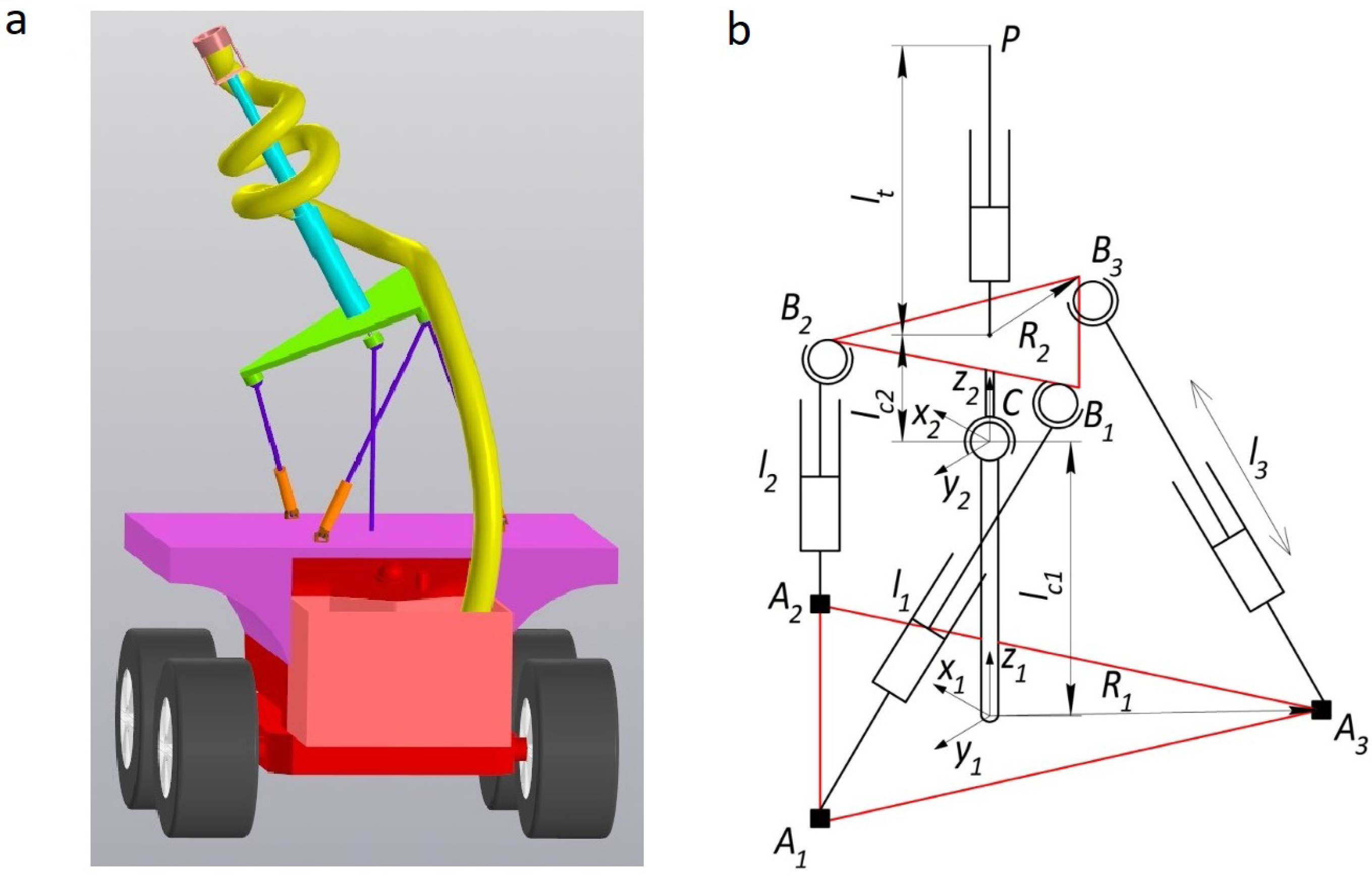
Consider the design of a fruit harvesting robotic system (RS) for harvesting fruit, the 3D model of which is shown in
Figure 1a. The RS includes a mobile platform with a basket for picking fruit, on which a parallel mechanism is installed [
15]. In the center of the moving platform, a telescopic link is installed for accessing fruits at high altitude.
The parallel mechanism consists of three drive RRPS-type kinematic chains and a central kinematic chain with a spherical joint rigidly connected to the fixed and movable platforms. Thus, the required rotation of the movable platform in all axes relative to the joint center C is provided by changing the lengths of the rods. The fixed platform and the moving platform of the mechanism are regular triangles with radii and , respectively.
The input coordinates are the lengths of the drive links
, the output coordinates are the coordinates of the point
P of the end-effector
. The point
P is located at a distance
from the center of the moving platform. Workspace determination has two stages. The first stage is determining the set of acceptable values of the angular coordinates of the moving platform relative to the joint
C. The second stage is determinng the set of coordinates
P of the end-effector for these values. The coordinates of
P in the moving coordinate system
:
The coordinates of the point
P can be calculated in the fixed coordinate system
where
M is the transition matrix from the moving coordinate system
to the stationary system
, which includes displacements along the
axis and rotation using Euler angles
, taking into account the orientation of the platform.
where
.
After the transformation, taking into account (
1)–(
3), we obtain
Let us introduce restrictions on the geometrical parameters of the mechanism
where
,
are determined by the design parameters of the mechanism;
is the length of the
i-th rod
where
, and
are the coordinates of the centers of the joints
and
, respectively, in the fixed
coordinate system. We can now define the coordinates of the joints
in the moving coordinate system
.
Let us express the coordinates of the joints
in the
coordinate system, taking into account (
3) and (
7)
We define the coordinates of the joints
in the fixed coordinate system
,
,
:
Thus, substituting (
8)–(
11) in (
6), we obtain an analytical dependence of the form
.
At the same time, we should take into account the presence of singularities in the mechanism, which significantly increase the dynamic loads on the links and cause the robot to lose control. We consider the method proposed in [
16] to determine singularities, based on the analysis of the Jacobi matrix, whose determinant has the form
where
is defined taking into account the formulas (
6), (
8)–(
11). Due to the cumbersome nature of the obtained formulas for each of the elements of the determinant, we give only the first one
where
The condition for the presence of singularities has the form
. It is necessary to ensure that the determinant of the Jacobi matrix is constant in sign to exclude singularities from the workspace. One of the following conditions must be added (
5): det
or det
, depending on the sign of the determinant.
We should also take into account the restriction associated with ensuring the orientation of the platform at which the telescopic link is directed up, since the orientation of the platform at which the telescopic link is directed down is not excluded by condition (
5).
The exclusion of link interference can be taken into account using the method described earlier by the authors in [
17]. Thus, taking into account the link interference and other restrictions in accordance with (
5), (
12), and (
14), the workspace in the coordinate space of the orientation of the moving platform of the parallel mechanism can be determined. The covering set of the workspace is obtained using the methods described in [
13], and then transformed into a partially ordered set of integers [
14].
3. Transferring Constraints to the Coordinate Space of the End-Effector
We can calculate the set of positions of the end-effector using formula (
4). In this case, the telescopic link due to extension is an interval
Using the representation of the workspace as a partially ordered set of integers, we define set B of coordinates of the end-effector
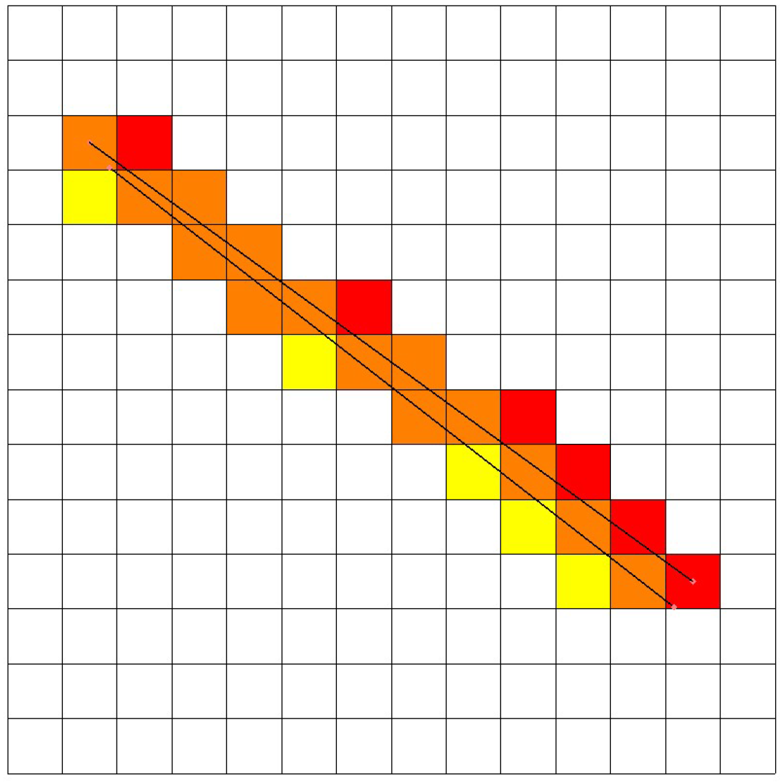
P in the space of integers. For this purpose, an algorithm is developed based on a modification of Bresenham’s algorithm [
18]. In [
19], a modification of the algorithm was proposed for the three-dimensional case, but the coordinates of the beginning and end of the segments belong to the space of integers, which leads to a displacement of the segment and set B (
Figure 2). Cells that intersect the orthosis are highlighted in red for coordinates represented as integers, yellow for coordinates represented as real numbers, and orange for both cases. As you can see from the figure, the application of integer coordinates does not allow us to accurately determine set B.
We modify Bresenham’s algorithm, taking into account the use of initial data belonging to the three-dimensional space of real numbers (coordinates
,
of the end-effector at
and
,
,
at
. In this case, the coordinates must correspond to the covering set of the workspace, represented as a partially ordered set of integers, respectively. They must be obtained taking into account the accuracy of the approximation
using formula (
4)
The pseudocode of the modified Bresenham algorithm proposed by the authors is presented in [
20].
4. Simulation Results
Let us perform a computational experiment. For this purpose, a software package was developed in the C++programming language. Parallel calculations were implemented using the OpenMP library. The visualization of link interference was performed using a developed Python script (Matplotlib and JSON libraries). The visualization of three-dimensional results was performed by exporting an ordered set of integers describing the work domain to the STL format. Simulation was performed for the following parameters:
= 300 mm,
= 200 mm,
= 360 mm,
= 600 mm,
= 500 mm,
= 0 mm,
= 500 mm, link diameter
= 20 mm, and minimum angle between links
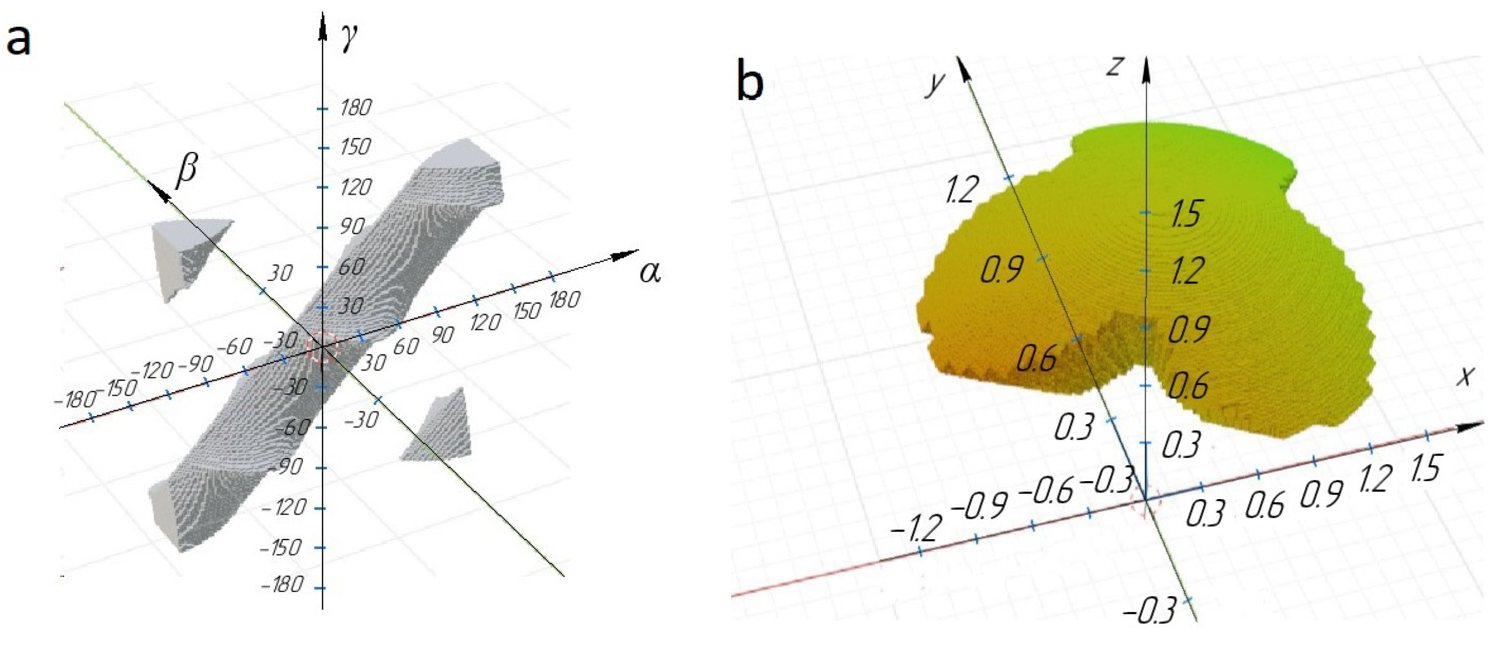
. The workspace in the coordinate space
of the moving platform orientation, without taking into account singularities, is shown in
Figure 3a.
Figure 3b shows the workspace in the coordinate space of the end-effector
.
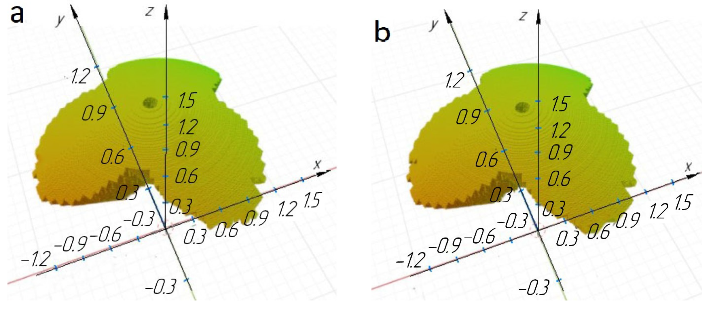
The workspace was determined both with the positivity condition (
Figure 4a and
Figure 5a) of the determinant and with the negativity condition (
Figure 4b and
Figure 5b) to select the sign in the sign-constant condition of the determinant of the Jacobi matrix, in order to exclude singularities.
Figure 4 and
Figure 5 show that the workspace in the coordinate space (
) is divided into two parts, but the workspace in the coordinate space (
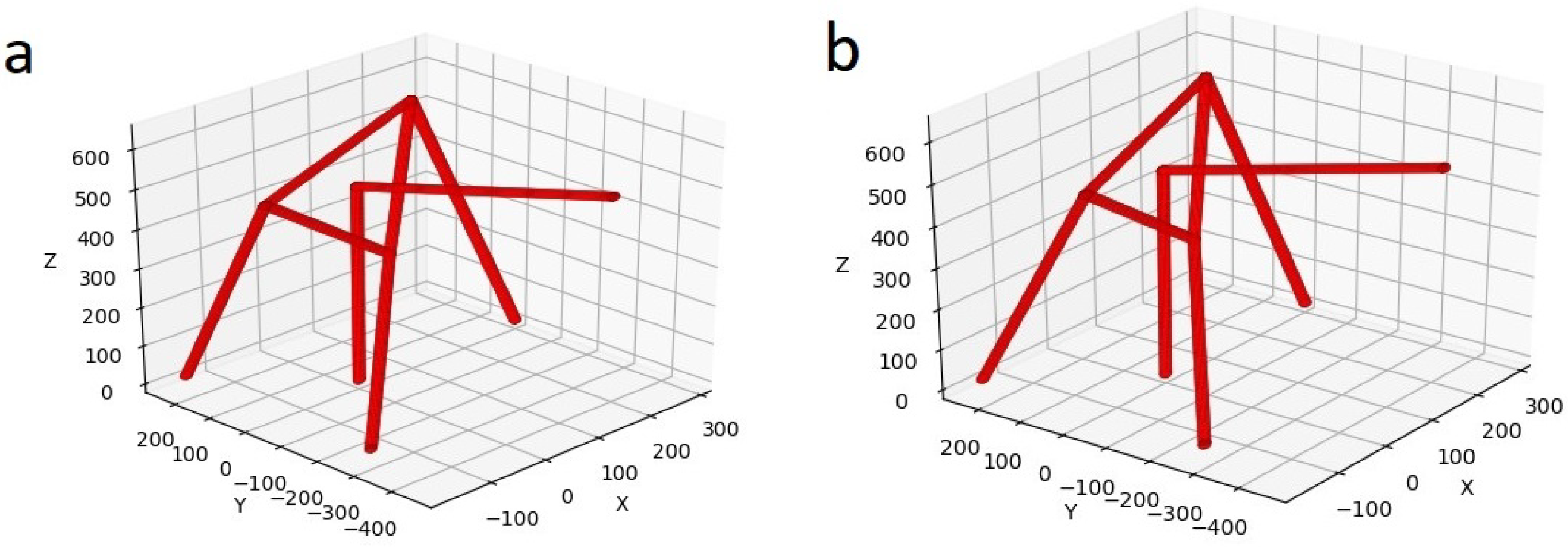
) practically coincides for different signs of the Jacobi matrix determinant. In both cases, the central zone in which the determinant of the Jacobi matrix is zero is excluded from the workspace. Thus, if the design of the RS gripper and fixing of the fruit harvesting tube will ensure fruit harvesting at any orientation of the end-effector, then both the condition of positivity and negativity of the determinant of the Jacobi matrix can be chosen. It is revealed that for the given initial data for modeling, there is no link interference. We will increase the ranges of changes in the length of the rods while maintaining the ratio
= 0.6 to ensure sufficient space inside the rod to accommodate ball–screw pairs. When the dimensions are increased to
= 420 mm,
= 700 mm, there is interference of the central kinematic chain on the moving platform (
Figure 6).
Increasing the length of the rods allows us to increase the volume of the workspace, but it is important to exclude the interference zones of links from the workspace.


