Proceeding Paper

Numerical Study of a PVDF-Based Strain Sensor for Damage Detection of an Asphalt Concrete Pavement Subject to Dynamic Loads †

1
Department of Engineering Technology, SUNY Polytechnic Institute, Utica, NY 13502, USA
2
Applied Physics Laboratory, Johns Hopkins University, Columbia, MD 20723, USA
3
Virginia Transportation Research Council, Charlottesville, VA 22903, USA
4
Department of Computer and Information Science, Arkansas Tech University, Russellville, AR 72801, USA
5
Department of Computer Science, SUNY Polytechnic Institute, Utica, NY 13502, USA
*
Author to whom correspondence should be addressed.
Presented at the 9th International Electronic Conference on Sensors and Applications, 1–15 November 2022; Available online: https://ecsa-9.sciforum.net/.
Eng. Proc. 2022, 27(1), 31; https://doi.org/10.3390/ecsa-9-13318
Published: 1 November 2022

Abstract

:
This paper studies the performance of Polyvinylidene fluoride (PVDF)–based strain sensor subject to dynamic loads with different load-moving velocities and the strain sensor’s performance for bottom-up crack detection of an asphalt pavement subject to dynamic loads. The core of the strain sensor is a metalized PVDF sensing film packaged with three protection layers. The encapsulated strain sensor adopts an H-shape to optimize the overall performance. Two numerical models are built in this paper and validate that the voltage output of the PVDF-based strain sensor can well capture the peak lateral strain with the propagation of the bottom-up cracks or the variation of a load moving velocity. Additionally, the sensor has better performance when it is in its lateral alignment position.

1. Introduction

As one of the essential components of road infrastructure, the health condition of asphalt concrete pavement affects the safety and quality of transportation due to various causes such as vibration induced by traffic, work zones or natural events, reflective cracks from an underlying layer and asphalt binder aging, etc. [1]. Therefore, asphalt concrete pavement fails over both top-down cracks and bottom-up cracks. Additionally, surface failure may be caused by bottom-up cracks, which are usually challenging to identify and localize. It is, therefore, critical to offer continuous structural health monitoring of asphalt concrete pavement using a non-destructive and cost-effective approach that can better detect defects of the bottom-up cracks and boost timely maintenance.
Currently, three prominent technologies are utilized by researchers to detect bottom-up cracks: ground penetrating radar (GPR) [2,3], ultrasonic technology [4,5], and in-pavement sensing technology [6,7]. GPR is a non-deconstructive technique that utilizes the difference in electromagnetic properties of the underground medium, reflections, and transmissions of electromagnetic waves generated at the interfaces of different electrical interfaces for measuring the targeting objects. Within a limited depth, GPR can offer three-dimensional scanning of the pavement. However, it is difficult for GPR to accurately locate cracks when the pavement is thick or contains high humidity [8,9]. Ultrasonic technology calculates the time from the start of the ultrasonic stress-wave pulse to the arrival of echo reflection for detecting cracks and joints in asphalt concrete pavement [10,11]. Ultrasonic technology allows for the detection of pavement distress at a medium-deep level. With the recurrence plot quantification analysis method, the reliability and sensitivity of ultrasonic technology can be improved in the damage detection of non-homogeneous materials [12]. Ultrasonic technology is still constrained by environmental conditions such as the moisture level in the pavement and weather changes; for instance, due to its low transmission capability, different material properties may be detected as the same material under different weather conditions [13,14]. In-pavement sensing technology usually measures cracks and road conditions using sensor arrays. One of the most popular sensors for damage detection is a strain gauge, including optical fiber [14], conventional electrical resistance strain gauge [15], metal-foil gauges [16], etc. Due to the harsh installation conditions of asphalt concrete pavement, high temperatures (up to 164 °C), and pressure (around 290 ksi) [17,18], metal-foil gauges are rarely used for asphalt concrete pavement. The conventional electrical resistance strain gauge is commonly used in asphalt pavement, but its installation requires digging holes in the pavement. The strain sensor is sealed in the pavement by a cold patch of asphalt concrete material, which material properties are different from the original asphalt concrete mixture, thus further affecting the results for damage detection. Optical fiber can offer accurate measurements, but the cost is relatively high [15].
Piezoelectric plastic materials such as PVDF can generate electrical charges when mechanically deformed, are commonly used for concrete structural health monitoring [19]. PVDF offers the advantages of high sensitivity, good flexibility, good manufacturability, small distortion, low thermal conductivity, high chemical corrosion resistance, and heat resistance. The authors have proposed a cost-effective piezoelectric-based strain sensor for damage detection of asphalt pavement [20] which can be integrated in a low cost internet of things based real-time pavement monitor system [21].This paper further studies the performance of strain sensors subject to dynamic loads with different load-moving velocities and the strain sensor’s performance for bottom-up crack detection of an asphalt pavement subject to dynamic loads. Section 2 briefly introduces the study’s sensor configuration and the finite element model. Section 3 elaborates on the results and discussion. The last section is the conclusion.

2. Materials and Methods

2.1. Sensor Configuration

The sensor designed in this paper is shown in Figure 1, which is validated by the authors’ previous study [20]. The outer layer uses epoxy resin as a coating layer, followed by polyurethane foam as a thermal insulation layer (thickness is 11 mm), and then an epoxy layer on the inside (thickness is 10 mm). The inner layer is PVDF (key sensing unit), and the size is 80 mm × 18 mm × 1 mm. The shape of the sensor is H-shape because H-shape can make the whole sensor sense the change of road surface better and can effectively transfer the deformation to the key sensing unit. The ratio of the middle beam length to side wing length is 3.2, which is the best ratio to detect pavement deformation. To overcome the high temperature of the sensor during the installation process, polyurethane foam is chosen as the insulation layer to be added to the outer layer. Araldite GY-6010 epoxy resin is selected as the material of epoxy resin because it has high tensile strength and flexural strength, as well as good heat insulation performance.

2.2. Finite Element Model

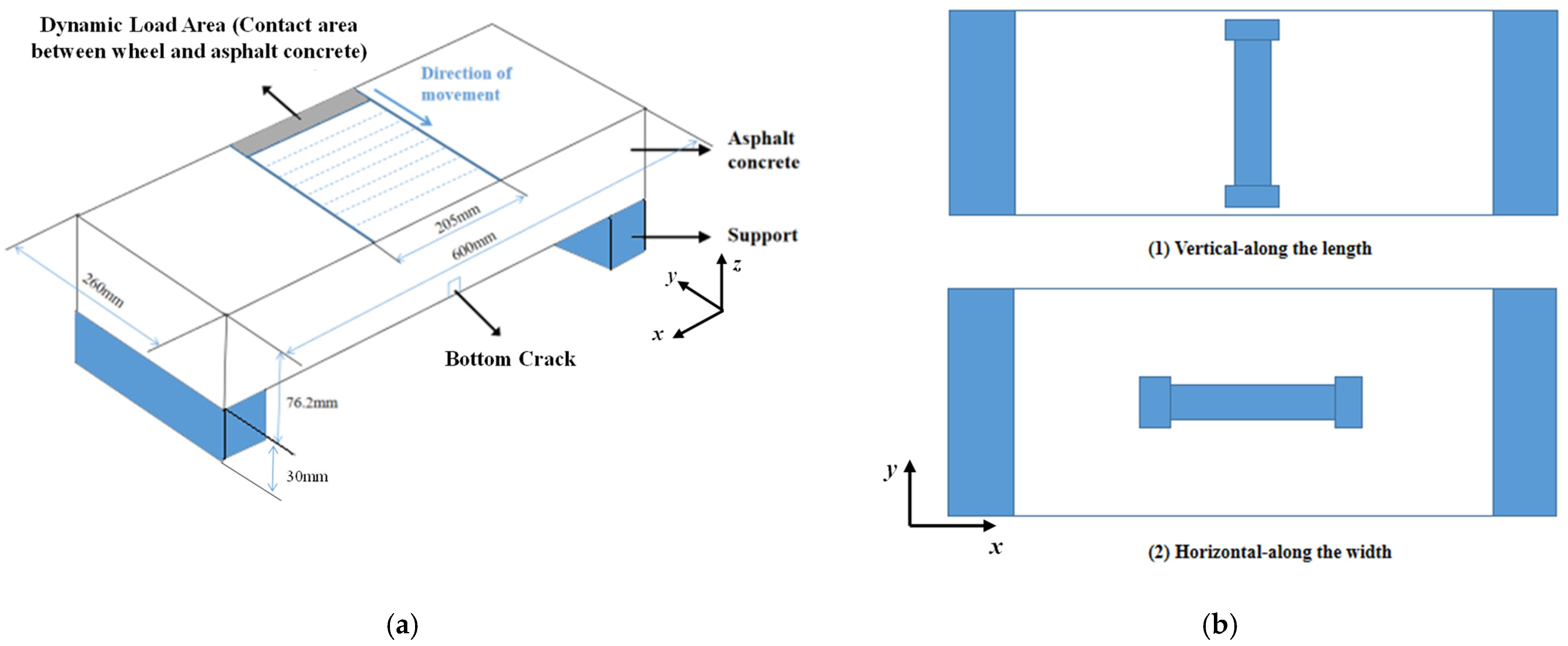
The paper established and simulated two sets of FEM in COMSOL Multiphysics, as shown in Figure 2a. In the first FEM study, with no bottom-up crack existing in the asphalt concrete pavement, the sensor output signal and measured strain at the bottom of the pavement in response to the load moving velocity are investigated. The moving speed of the same dynamic load varies from 25 km/h to 75 km/h with an increment of 10 km/h. In the second FEM study, a bottom-up crack initiates at the center of the bottom surface of the pavement along the x-axis. The crack depths vary from 0 cm (0 inches) to 7.62 cm (3 inches) with 1.27 cm (0.5 inches) increments. In the FEM, the same dynamic load with a fixed load moving velocity is applied on the top surface of the pavement, as shown in Figure 2a. In addition, the sensor is placed in two directions (horizontal and vertical) for both FEM studies, as shown in Figure 2b, for studying the impact of the sensor alignment in response to the bottom-up crack detection.
In both FEM studies, the asphalt concrete pavement has a size of 600 mm × 260 mm × 76.2 mm. Two supports are placed at two ends of the bottom of the pavement. A customized strain sensor is attached underneath the center of the bottom surface of the asphalt concrete pavement, as shown in Figure 2a. This paper subdivides the grid for the strain sensor to better investigate the sensor’s responses in terms of sensing the bottom-up cracks. During the dynamic simulation, a dynamic load is applied to the middle region of the upper surface of the asphalt concrete pavement. The contact area of the dynamic load on the pavement surface is 215 mm × 30 mm to mimic the contact area of a car tire on the pavement in an actual application. In addition, the dynamic load of 90.72 tons (200 kips) is chosen to mimic the weight of a moving overweight truck [22]. In the FEM, asphalt concrete is simulated as a viscoelastic material. As such, the asphalt concrete’s shear modulus and relaxation time are set as 10 MPa and 0.3 s in the FEM, respectively. The properties of each material are shown in Table 1.

3. Results and Discussion

Figure 3a,b shows the measured strain sensor output and the measured lateral strain (along the x-axis) in response to different load-moving velocities when there is no crack existing in the pavement. The strain sensor is aligned vertically (along the y-axis) in Figure 3a and laterally (along the x-axis) in Figure 3b. Figure 3a,b indicates that the measured sensor output has the same trend as the lateral strain, which means the strain sensor, no matter if it is aligned vertically or laterally, can accurately capture the lateral strain of the pavement. However, Figure 3a,b also shows that the strain sensor is more sensitive to lateral strain when the strain sensor is aligned laterally.
In Figure 3a, the sensor is aligned vertically. The sensor output decreases when the load moving velocity increases from 25 km/h to 35 km/h and from 45 km/h to 65 km/h, and increases slightly when the load moving velocity increases from 35 km/h to 45 km/h and from 65 km/h to 75 km/h. Please notice that the measured lateral strain is negative. Therefore, the trend of the absolute value of the lateral strain is precisely opposite to the sensor output except when the load moving velocity is between 65 km/h and 75 km/h. The possible reason is the pavement structure in FEM reaches its resonance frequency when the load moving velocity is between 65 km/h and 75 km/h.
In Figure 3b, the sensor is aligned laterally. The sensor output increases slightly when the load moving velocity increases from 25 km/h to 35 km/h and from 65 km/h to 75 km/h, and decreases continuously when the load moving velocity increases from 35 km/h to 65 km/h. The lateral strain measured above the sensor also shows the same trend. Similarly, the possible reason is the pavement structure in FEM reaches its resonance frequency when the load moving velocity is from 65 km/h to 75 km/h.
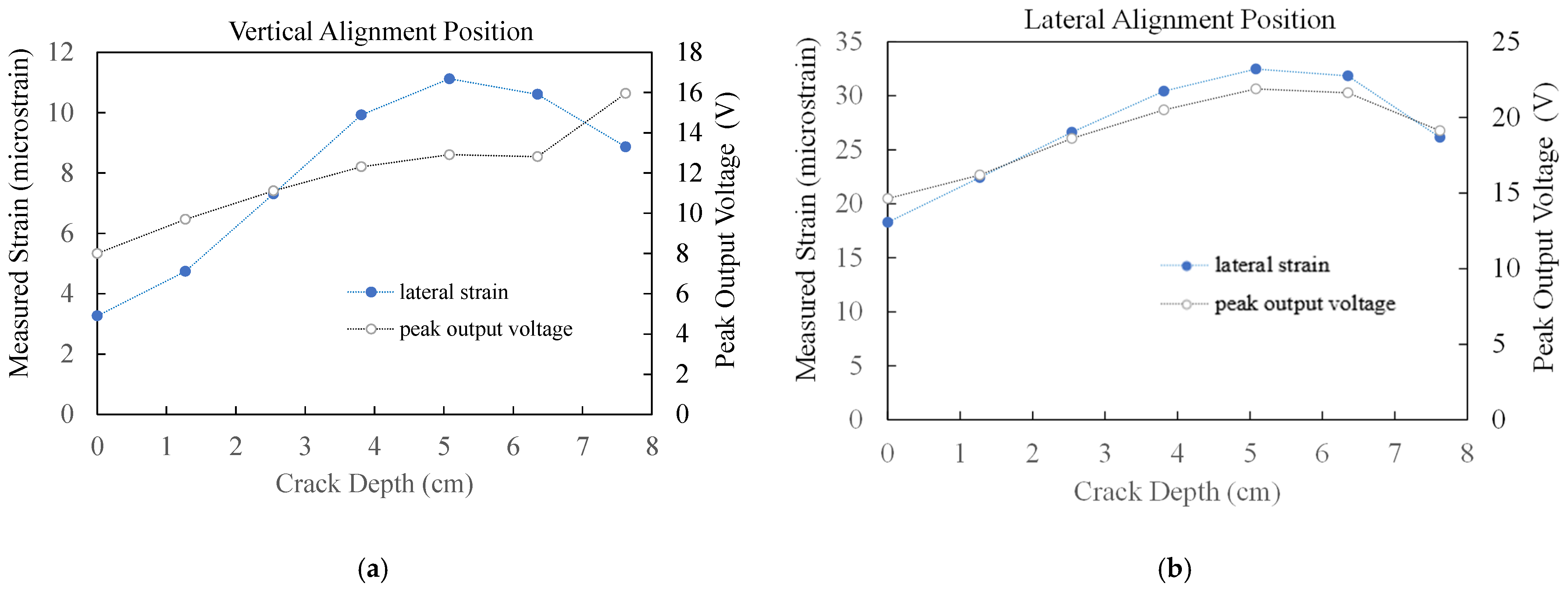
Figure 4a,b shows measured lateral strain (along the x-axis) and peak piezoelectric-based sensor output in response to the depth of the bottom-up crack when the dynamic load moving velocity equals 25 km/h. The strain sensor is aligned vertically (along the y-axis) in Figure 4a and laterally (along the x-axis) in Figure 4b. Before the crack depth reaches the whole pavement thickness, the trend of the sensor output is totally aligned with the trend of the lateral strain, no matter whether the sensor is aligned vertically or laterally, as shown in Figure 4a,b. When the pavement completely breaks (the crack depth = the pavement thickness), the decreasing trend of lateral strain is captured by the sensor output in Figure 4b but not well represented by the sensor output in Figure 4a. In other words, the strain sensor output can better capture the strain change with the lateral alignment position. Furthermore, sensor output and lateral strain are much larger when the sensor output is in a lateral alignment position.
In Figure 4a, when the crack depths initiate and propagate from 0 cm (0 in) to 5.08 cm (2 in), both sensor output and lateral strain gradually go up. When the crack depth propagates from 5.08 cm (2 in) to 6.35 cm (2.5 in), the sensor output and lateral strain show a decreasing trend. Then the lateral strain continuously decreases but the sensor output increases when the crack depth grows from 6.35 cm (2.5 in) to 7.62 (3 in).
In Figure 4b, the sensor output and measured lateral strain increase almost linearly with the increase of the crack depth from 0 cm (0 in) to 3.81 cm (1.5 in). Then the increasing trend slows down when the crack depth increases from 3.81 cm (1.5 in) to 5.08 cm (2 in). The measured lateral strain and sensor output reduce with an increasing trend of the crack depth from 5.08 cm (2 in) to 7.62 cm (3 in). In Figure 4a,b, the measured lateral strain has a similar trend no matter whether the strain sensor is aligned vertically or laterally. However, the measured lateral strain is much more prominent when the strain sensor is aligned laterally.

4. Conclusions

This paper studies the proposed strain sensor subject to dynamic loads with different load-moving velocities and the strain sensor’s performance for bottom-up cracks detection of an asphalt pavement subject to dynamic loads. The results of this study validate that the proposed strain sensor can cause a differential of the load moving velocity by the measured lateral strain. In addition, the strain sensor can detect the initiation and propagation of a bottom-up crack and capture the peak of the lateral strain before the pavement is entirely broken. Both numerical studies demonstrate that the sensor has better outputs when aligned laterally.

Author Contributions

Conceptualization, J.S., K.B., A.T. and I.B.; methodology, J.S.; software, M.G.; validation, J.S. and W.C.; formal analysis, J.S., M.G. and W.C.; investigation, J.S., K.B. and A.T.; resources, I.B.; data curation, J.S.; writing—original draft preparation, J.S.; writing—review and editing, K.B., A.T. and I.B.; visualization, J.S.; supervision, J.S.; project administration, J.S.; funding acquisition, J.S., K.B., A.T. and I.B. All authors have read and agreed to the published version of the manuscript.

Funding

This research was funded by the 2020 Virginia Transportation Research Council Award #116019.

Institutional Review Board Statement

Not applicable.

Informed Consent Statement

Not applicable.

Data Availability Statement

Not applicable.

Conflicts of Interest

The authors declare no conflict of interest.

References

  1. Adlinge, S.S.; Gupta, A. Pavement deterioration and its causes. Int. J. Innov. Res. Dev. 2013, 2, 437–450. [Google Scholar]
  2. Salvi, R.; Ramdasi, A.; Kolekar, Y.A.; Bhandarkar, L.V. Use of ground-penetrating radar (GPR) as an effective tool in assessing pavements—A review. In Geotechnics for Transportation Infrastructure; Springer: Singapore, 2019; pp. 85–95. [Google Scholar] [CrossRef]
  3. Georgiou, P.; Loizos, A. Parametric optimization of ground penetrating radar approach for assessing asphalt pavement surface layers compaction. J. Appl. Geophys. 2020, 182, 104187. [Google Scholar] [CrossRef]
  4. Behera, H.K.; Pradhan, S.; Das, S.S. Low cost ultrasonic roughometer for pavement roughness measurement. Innov. Infrastruct. Solut. 2021, 6, 1–13. [Google Scholar] [CrossRef]
  5. du Tertre, A.; Serhan Kırlangıç, A.; Cascante, G.; Tighe, S.L. A non-destructive approach for the predictive master curve of ASPHALT pavements using ultrasonic and deflection methods. Int. J. Pavement Eng. 2022, 23, 1540–1551. [Google Scholar] [CrossRef]
  6. Ma, X.; Dong, Z.; Dong, Y. Toward asphalt pavement health monitoring with built-in sensors: A novel application to real-time modulus evaluation. IEEE Trans. Intell. Transp. Syst. 2022, 23, 22040–22052. [Google Scholar] [CrossRef]
  7. Liu, Z.; Gu, X.; Wu, C.; Ren, H.; Zhou, Z.; Tang, S. Studies on the validity of strain sensors for pavement monitoring: A case study for a fiber Bragg grating sensor and resistive sensor. Constr. Build. Mater. 2022, 321, 126085. [Google Scholar] [CrossRef]
  8. Benedetto, A. A three dimensional approach for tracking cracks in bridges using GPR. J. Appl. Geophys. 2013, 97, 37–44. [Google Scholar] [CrossRef]
  9. Luburić, I.; Perić, Z.; Šesnić, S. Electromagnetic modeling of the GPR response to the pipe system set in the concrete slab. In Proceedings of the 2017 25th International Conference on Software, Telecommunications and Computer Networks (SoftCOM), Split, Croatia, 21–23 September 2017; pp. 1–5. [Google Scholar] [CrossRef]
  10. du Tertre, A.; Kırlangıç, A.S.; Cascante, G.; Tighe, S.L. Ultrasonic inspection of asphalt pavements to assess longitudinal joints. Road Mater. Pavement Des. 2022, 23, 129–148. [Google Scholar] [CrossRef]
  11. Pan, W.-H.; Sun, X.-D.; Wu, L.-M.; Yang, K.-K.; Tang, N. Damage detection of asphalt concrete using piezo-ultrasonic wave technology. Materials 2019, 12, 443. [Google Scholar] [CrossRef] [PubMed]
  12. Carrión, A.; Genovés, V.; Gosálbez, J.; Miralles, R.; Payá, J. Ultrasonic signal modality: A novel approach for concrete damage evaluation. Cem. Concr. Res. 2017, 101, 25–32. [Google Scholar] [CrossRef] [Green Version]
  13. Al-Qadi, I.L.; Sebaaly, P.E.; Wambold, J.C. New and Old Technology Available for Pavement Management System to Determine Pavement Condition; ASTM International: West Conshohocken, PA, USA, 1991. [Google Scholar] [CrossRef]
  14. Salles, L.; Balbo, J.T.; Khazanovich, L. Non-destructive ultrasonic tomography for concrete pavement evaluation: Signal processing and image analysis of crucial parameters. Rev. IBRACON De Estrut. E Mater. 2017, 10, 1182–1191. [Google Scholar] [CrossRef] [Green Version]
  15. Lydon, M.; Taylor, S.E.; Robinson, D.; Callender, P.; Doherty, C.; Grattan, S.K.; O’Brien, E.J. Development of a bridge weigh-in-motion sensor: Performance comparison using fiber optic and electric resistance strain sensor systems. IEEE Sens. J. 2014, 14, 4284–4296. [Google Scholar] [CrossRef]
  16. Zhao, H.; Wu, C.; Wang, X.; Zheng, Y. Pavement condition monitoring system at shanghai pudong international airport. In Proceedings of the Geo-Shanghai 2014 International Conference, Shanghai, China, 26–28 May 2014; pp. 283–295. [Google Scholar] [CrossRef]
  17. Lajnef, N.; Chatti, K.; Chakrabartty, S.; Rhimi, M.; Sarkar, P. Smart Pavement Monitoring System; Federal Highway Administration: McLean, VA, USA, 2013.
  18. Kim, Y.R.; Seo, Y.; King, M.; Momen, M. Dynamic modulus testing of asphalt concrete in indirect tension mode. Transp. Res. Rec. 2004, 1891, 163–173. [Google Scholar] [CrossRef]
  19. Du, G.; Li, Z.; Song, G. A PVDF-based sensor for internal stress monitoring of a concrete-filled steel tubular (CFST) column subject to impact loads. Sensors 2018, 18, 1682. [Google Scholar] [CrossRef] [PubMed] [Green Version]
  20. Shen, J.; Geng, M.; Schultz, A.; Chen, W.; Qiu, H.; Wang, X. Numerical Study of a Multi-Layered Strain Sensor for Structural Health Monitoring of Asphalt Pavement. Multidiscip. Digit. Publ. Inst. Proc. 2019, 42, 41. [Google Scholar] [CrossRef] [Green Version]
  21. Bekiroglu, K.; Tekeoglu, A.; Shen, J.; Boz, I. Low-Cost Internet of Things Based Real-Time Pavement Monitoring System. In Proceedings of the 2021 IEEE International Conferences on Internet of Things (iThings) and IEEE Green Computing & Communications (GreenCom) and IEEE Cyber, Physical & Social Computing (CPSCom) and IEEE Smart Data (SmartData) and IEEE Congress on Cybermatics (Cybermatics), Melbourne, Australia, 6–8 December 2021; pp. 17–22. [Google Scholar] [CrossRef]
  22. Nowak, A.S.; Laman, J.A.; Nassif, H. Effect of Truck Loading on Bridges; Michigan Department of Transportation: Lansing, MI, USA, 1994.
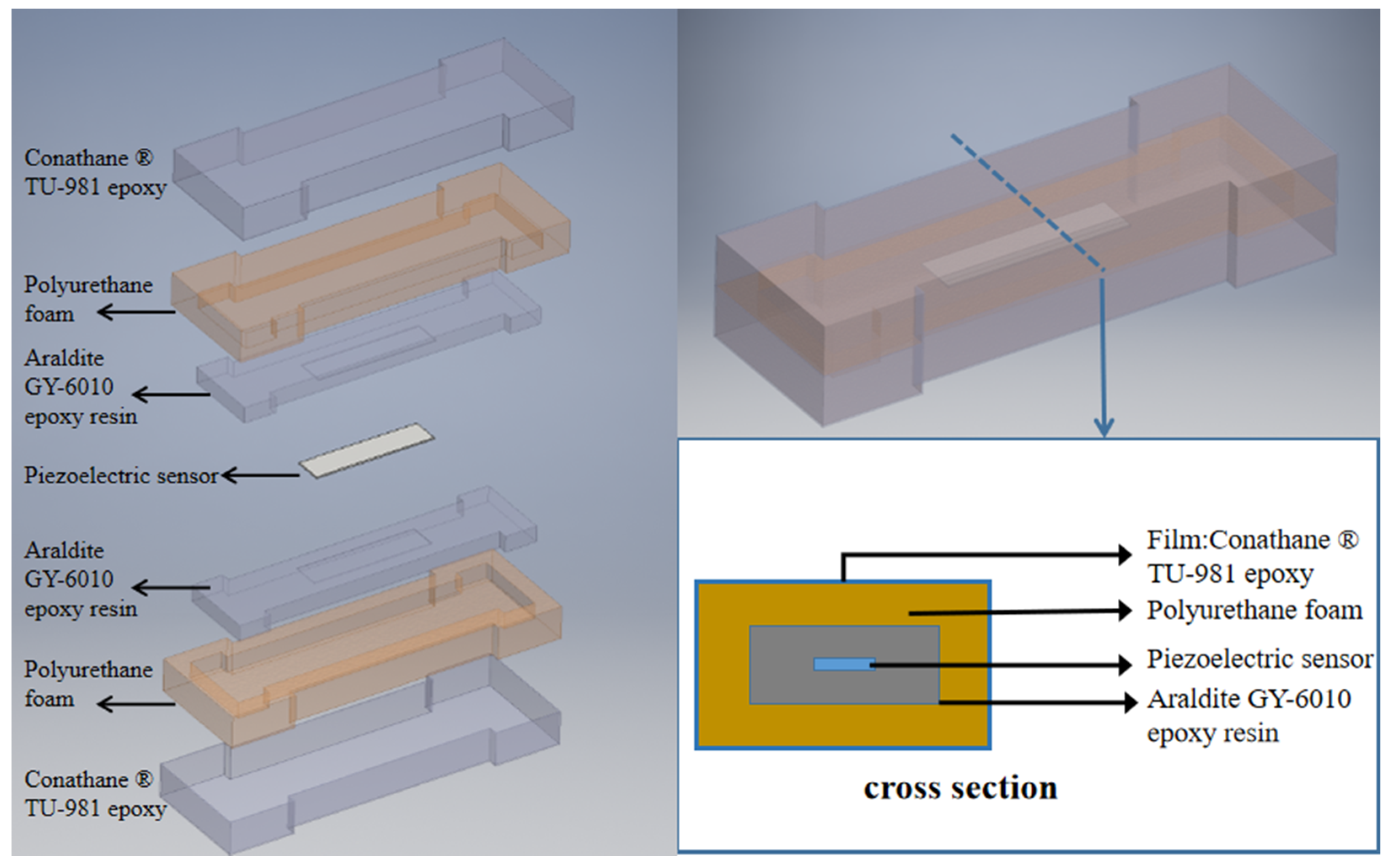
Figure 1. Configuration of the strain sensor.
Engproc 27 00031 g001
Figure 2. (a) Schematic of the numerical model of a dynamic load passing through the road surface. (b) Bottom view of the numerical model for showing sensor alignment.
Engproc 27 00031 g002
Figure 3. Measured lateral strain (along the x-axis) and peak piezoelectric-based sensor output in response to the dynamic load moving velocity when there is no bottom-up crack existing in the asphalt concrete pavement (crack depth = 0 cm): (a) sensor is vertically aligned (along the y-axis); (b) sensor is laterally aligned (along the x-axis).
Engproc 27 00031 g003
Figure 4. Measured lateral strain (along the x-axis) and peak piezoelectric-based sensor output in response to the depth of the bottom-up crack when the dynamic load moving velocity equals 25 km/h: (a) sensor is vertically aligned (along the y-axis); (b) sensor is laterally aligned (along the x-axis).
Engproc 27 00031 g004
Table 1. Key material properties used in FEM.
MaterialDensity (kg/m3)Young’s Modulus (GPa)Poisson’s Ratio
Asphalt concrete2402.7712 0.3
Polyurethane foam500.1510.37
Araldite GY-6010 epoxy resin27002.0670.37
Piezoelectric sensor178020.39
Publisher’s Note: MDPI stays neutral with regard to jurisdictional claims in published maps and institutional affiliations.