1. Introduction
The insurance of structural safety is the main objective of structural detailing. It is believed that earthquakes are natural disasters. Every year, many people lose their lives during earthquakes due to earthquake-based structural failure. We can minimize structure damage by applying earthquake-resistant design standards, i.e., applying the philosophy of seismic and nonseismic detailing within the design parameters. This paper presents a detailed and relative investigation of RCC detailing area elements in multistory structures between a nonseismic analysis and a seismic analysis. Providing reinforced concrete is more important since it predicts failure and helps to collapse and damage the structure. This is especially true in earthquake-prone areas. An analysis was performed using different software, such as BIM, ETABS, SAFE, STAADPRO, and AutoCAD [
1,
2]. At first, we modeled the structure, and then we applied a new load combination. For the comparisons, the critical values derived from the load combination were used.
During an earthquake, there is a great chance of structural collapse; to stop the structure from collapsing, we must provide reinforcement detailing. In order to make sure the structure is safe, we provide detailing according to different seismic codes. We can achieve good ductility in the structure if we provide the detailing carefully. The role of reinforcement detailing for area elements is very effective because it helps make the structure strong, durable, and ductile. In order to resist seismic loading, we need to enhance the compressive and tensile strength of the RCC area elements. The area elements (slabs and foundations) were designed in such a way that they can resist the seismic loads and can engage stresses, like compressive stress, shear stress, and tensile stress, in the structure.
We can achieve economy by speeding up the construction process by using BIM tools. With the help of this, more time can be saved. It is the only tool that helps us to boost the construction process. Similarly, it can also help us to reduce the wastage of materials in construction, which directly helps save materials and resources and achieves better economics. In the architecture, engineering, and construction (AEC) industry, many other optimization approaches are also applied to achieve economy.
2. Nonseismic and Seismic Detailing of Area Elements
2.1. Detailing of Seismic and Nonseismic Factors for Slabs
Due to earthquake loadings, it is necessary to provide seismic detailing for slabs. The seismic slab should be designed in line with the seismic zone, in which the structure is made. According to the UBC (1997), the behavior of slabs changes with regard to the seismic zone it is in because, in every seismic zone, there are different seismic forces that are dormant, from which the slab is subjected to more failure. Additionally, from the detailing perspective in seismic detailing, we have to provide a lap. The place for the lap in the case of seismic detailing is different compared to nonseismic detailing. In the seismic detailing, we provide a lap at the middle of the slab. Some other parameters are also considered, like moment-resistant frame concepts in the case of seismic analysis. These frames play a vital role in seismic detailing. Providing proper reinforcement detailing makes the structure strong, durable, and ductile [
3].
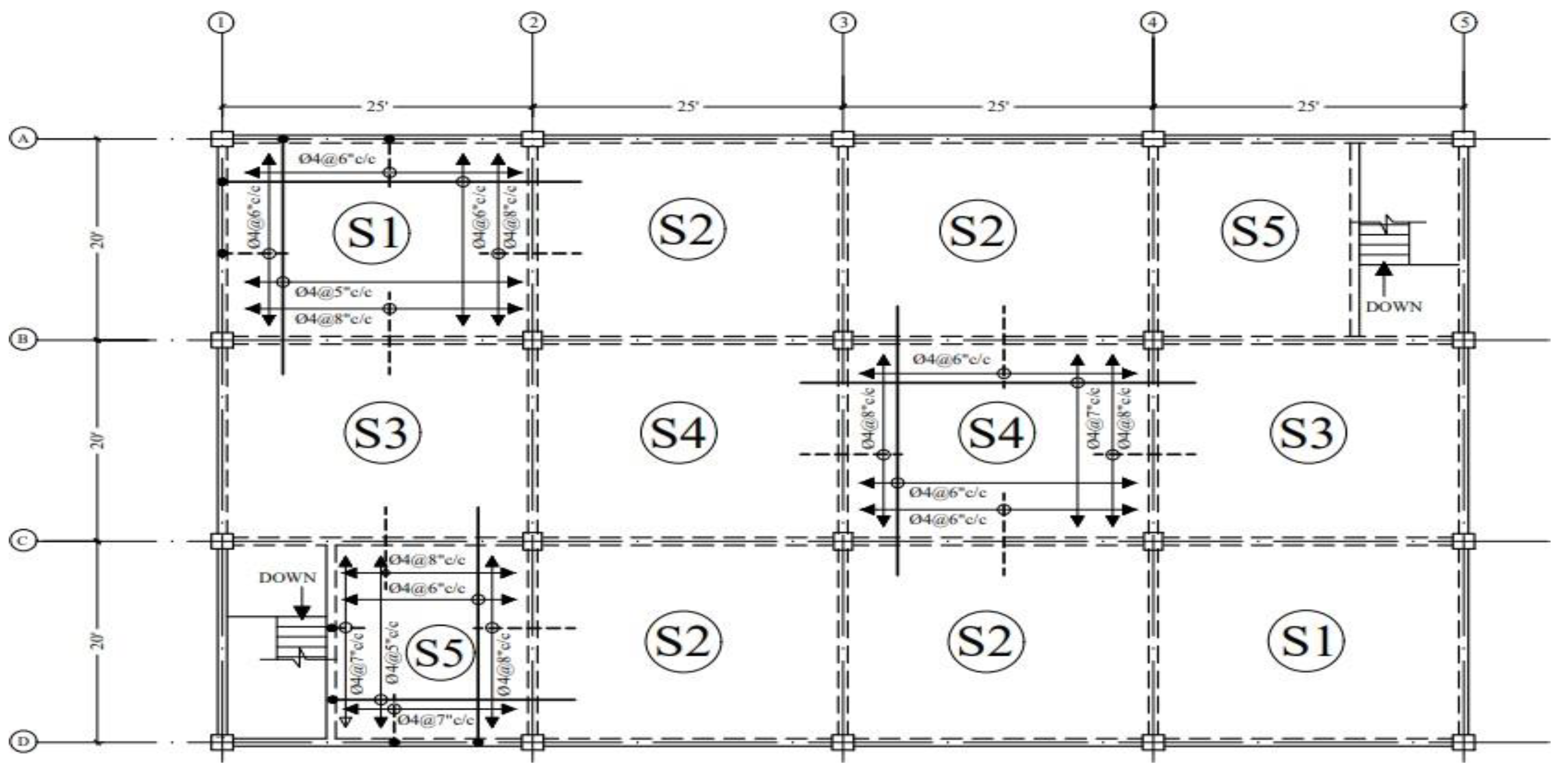
Figure 1 highlights seismic slab reinforcement detailing, indicating that the lap location was made in the middle of the slab to make the slab ductile, strong, and more durable. If the slab is designed in a certain way, then RCC slabs work similarly to beams. Lapping bars at the point of the least bending moment or at point s of contraflexure is optimal. Laps are essentially given beyond L/3 to L/4 (L is the effective slab span) from the support of the bars at the bottom of the slabs. The top bars are often short, so no laps are required. However, the lapping bars must never surpass one-third of the total bars. For two-way slabs, the same setup may be adopted but in both directions.
During the earthquake, the slab structure shows large displacement due to flexibility, which is not acceptable under lateral loading. The literal load caused by the earthquake on a slab is the most important and determinant effect on the structure. When compared to gravity loading, the earthquake load has a greater effect on structures, which affects the structure more as the structural height increases. Structure stability depends on the overturning moment as well as the structure height. A structure with appropriate seismic detailing will carry earthquake loading, while a structure without the appropriate structural system can fail [
4].
During an earthquake, the key section of RCC constructions, the beam-column and slab connection, is subjected to tremendous shear stresses and highly inelastic deformations, culminating in the failure of the whole structure [
5]. As a result, we required effective ways to reinforce beam-columns and slabs. More traditional methods have been investigated, including the bolted steel plates [
6], the concrete-replacing method, the enlarging of an area method [
7], and strengthening with fiber-reinforced polymers (FRPs) [
8]. The type of failure in reinforced specimens is failure due to bending in the beam rather than brittle failures in the joint because of the increased joint area, whereas the horizontal shear stress is uneven [
9]. Ultra-high-performance hybrid fiber-reinforced concrete (UHP-HFRC) is utilized as a new method of replacing concrete to increase the loading capacity of tensile loads at joints with little or moderate damage, but this has only had minimal impact on the ductility of several damaged joints [
10].
2.2. Nonseismic and Seismic Detailing for Footings
The importance of ground conditions in the selection of design parameters was essential in the design process of nonseismic and seismic detailing for foundations, and we also examined different modes of failure. The seismic loads that were acting on a structure during the earthquake depend on the location and seismic zones as well as the conditions of the subsurface on the site [
11]. The design of seismic footings in the structure mainly depends on the dynamic bearing capacity of the soil. The design of the footings depends on different aspects, such as the location of the site, the condition of the site, the soil parameter, and the seismic zone. In order to increase the strength stiffness and durability of the foundation, it is very important to provide high-strength steel reinforcements and resist the seismic loading effects. By analyzing the seismic design of the foundation, we obtained the strength and stiffness of the footing in different zones and depths. Most of the analysis for the design of the seismic loads of foundations relies on the concept that the failure of the zones in the soil occurs along with static surface failure [
12].
Throughout the world, various codes of practice have been offered as diverse approaches for evaluating the seismic activity of a structure. The most important element for the appropriate seismic detailing of footings is to calculate the loads transferred to the foundation during the earthquake. This is determined by the nonseismic and seismic loads that were operating on the superstructure during the earthquake [
13]. For structures, such as buildings, to have good performance, they must have suitable column-footing joints. The column-footing joint is a critical connection that affects structural performance under dynamic loads [
14].
Figure 2 shows the detailing of the footing or foundation reinforcement in a seismic zone, where providing high-strength steel reinforcement is necessary to increase the strength stiffness and durability of the foundation. Estimating the loads transferred to the foundation during an earthquake is critical for the effective seismic design of the foundation.
3. The Efficient Aspects Achieved in Detailing the Area Elements
The slab and foundation costs were optimized following British requirements. The primary purpose of the cost function includes the foundation, floor, and slab costs, as well as the costs of concrete, labor reinforcements, formworks, and the cost of materials. When analyzing a structure, the equivalent frame technique is applied. Optimization was carried out in three steps: foundation layout optimization and foundation dimensions, slab thickness optimization, and reinforcement number and size optimization for the reinforced concrete members. As a result, three flat slabs were used as examples for optimization, and the outcomes have been correlated with each other. The results show that the optimization saves more on costs when compared to traditional designs. There is a direct relationship between the cost-saving and the number of elements in the structure, which shows that if the cost of the RCC elements in a structure is higher, more money can be saved [
15].
According to British standards (BS8110), RCC slab optimization has been investigated. The main objective of the optimization technique is to reduce the thickness of the slab. This helps to reduce the overall slab cost by determining the most appropriate percentage of steel reinforcement and maintaining the required safety standards for the slab [
16]. In the case of slab cost optimization, the genetic algorithm (GA) method was used. The genetic algorithm method is a built-in feature of MATLAB. As the genetic algorithm (GA) uses a combination of objective functions to function, we needed to reduce the number of these. Certain elements in the objective functions need to be tried within the algorithm combinations. The best feasible proportion of steel reinforcement has been used to provide the most economical and maximum cost-effective thickness for the slabs in the middle of the strip, as well as in the column’s strip [
17].
The cost optimization method in the design of the RCC foundation could also be used successfully. In order to determine the most suitable and economical design for the RCC foundation, the genetic algorithm (GA) method was used. The prime objective of this technique is to reduce the total amount of the RCC foundation, considering the costs of steel, formwork, and concrete, while maintaining the required safety criteria for the foundation, according to the building design code. The American Concrete Institute ACI 318-19 has evaluated this approach for the design of RCC foundations within the scope of a concrete structure and the required safety codes of buildings. The genetic algorithm will assist in determining the least amount of steel reinforcing, and reducing the dimensions of the RC foundation for a certain set of applied forces and other criteria. As a result, it will help to cut material costs, while meeting all of the ACI 318-19 code design standards for footing designs [
18].
4. The Need for BIM Tool Automation
BIM is an advanced technology and a well-known tool. It was created in 1974 [
19]. Studies and investments in BIM have facilitated the development of related industries. The integration of BIM within other sectors, such as engineering, management, technological advances, and architectural and operational aspects, has been studied by researchers [
20]. For the use of BIM technology in sustainability, some standards and guidelines were thoroughly evaluated regarding BIM tool adoption [
21]. Other tools for facility management, the scheduling of simulations, analyzing design performance, emergency response, detecting conflicts, management, construction administration, and off-site manufacturing have been developed when BIM technology was deployed through BIM tools. For the time being, BIM is also utilized to increase model visualization in a range of scenarios, such as sign system visibility [
22].
In the construction industry, BIM is considered an additional tool that helps to achieve engineering goals. More precisely, we can achieve the potential of BIM by using BIM software and hardware. BIM services provide a plethora of well-developed tools, and the only thing left for local customers to do is learn how to use them [
23]. Because some of the technologies were incompatible, specialists are investigating file transformation and data management based on IFC to construct BIM applications. A few of them assist in furthering the progress of BIM and the AEC sector. Other well-known tools facilitate BIM development online. However, many of them perform similar functions and only in certain situations [
24], making it more difficult for the user to pick the relevant tools. The usefulness of information exchange between the modelers and management during the project may be constrained due to inadequate tool selection. A barrier that caused a low uptake of the BIM tool in the AEC industry is the lack of knowledge of BIM tools on a large scale [
25].
Steel reinforcements for intricate buildings may be designed using effective and strong BIM technology. Because BIM is a leading technology, with many benefits, it offers the architectural, engineering, and construction (AEC) sector a fresh perspective [
26]. Using BIM technology for the automated optimization of structures has become very popular among researchers [
27,
28]. Yet some tools are missing; when we export the architectural model designed in Revit into the Autodesk Robot Structural Analysis Professional (ARSAP), several elements are lost that the research community did not consider during the detailing phase. As a result, the involvement of skilled humans is required for the selection of rebars after the analysis of data exporting from ARSAP to Revit.
For the use of BIM in the industry, despite the studies carried out, no concrete research has been carried out on the efficient use of BIM in projects [
29]. The implications of using BIM tools on projects have not been studied in detail. There is a lot of software and equipment that fulfill comparable functions, but there is no peer-reviewed literature on BIM tools in the AEC industry. As a result, in order to adopt BIM software systems, it is necessary to study and provide a thorough review of BIM tools in the AEC industries.
5. Conclusions
Traditionally, in structural detailing, human involvement is required, which is error-prone and a time-consuming process. The following are the conclusions made from the preceding literature:
The structural detailing of area elements is needed to improve the strength and ductility of the members;
- ▪
As per the codes for slab detailing, the rebars are computed on the base of the area of steel at a specified, governed location;
- ▪
As per the codes for footing detailing, the rebars are computed on the base of the area of steel at a specified, governed location;
In the AEC industry, better economics can be achieved by speeding up the construction process or saving materials by optimizing BIM tools;
BIM is a useful tool, but there are some features that are missing that need to be improved by the research community by making some advancements in BIM tool functionality.
In the seismic and nonseismic detailing of area elements, the selection of rebars is based on the building codes and the area of steel at particular governing locations without taking into consideration the steel area at other locations because it is a time-consuming and costly process. Making breakthroughs with the BIM tool can help with the structural detailing of area elements to automatically choose the rebars through their consistency and coherency, saving us time and resources.
Author Contributions
Conceptualization, A.A.S. and M.A.; methodology, A.A.S. and M.A.; software, A.A.S.; investigation, A.A.S.; writing—original draft preparation, A.A.S.; writing—review and editing, M.A.; supervision, M.A. All authors have read and agreed to the published version of the manuscript.
Funding
This research received no external funding.
Institutional Review Board Statement
Not applicable.
Informed Consent Statement
Not applicable.
Data Availability Statement
The data will be available on reasonable request.
Acknowledgments
The authors would like to express their gratitude to everyone who assisted them with their literature review.
Conflicts of Interest
To the best of the authors’ knowledge, there is no conflict of interest. They have no known competing financial or personal interests that could have appeared to affect the work disclosed in this study.
References
- Ahmad, S.; Ali, M. Comparative study of analysis and design of high-rise building in nonseismic and different seismic zones. In Proceedings of the 2nd Asian Concrete Federation (ACF) International Conference, Bali, Indonesia, 20–21 November 2006. [Google Scholar]
- Habte, B.; Guyo, E. Application of BIM for structural engineering: A case study using Revit and customary structural analysis and design software. J. Inf. Technol. Constr. 2021, 26, 1009–1022. [Google Scholar] [CrossRef]
- Awkar, J.C.; Lui, E.M. Seismic Analysis and Response of Multistorey Semi-Rigid Frames. Eng. Struct. 1999, 21, 425–441. [Google Scholar] [CrossRef]
- Cano, M.T.; Klingner, R.E. Comparison of Analysis Procedures for Two Way Slabs. ACI Struct. J. 1988, 85, 597–608. [Google Scholar] [CrossRef]
- Shen, D.; Li, M.; Kang, J.; Liu, C.; Li, C. Experimental studies on the seismic behavior of reinforced concrete beam-column joints strengthened with basalt fiber-reinforced polymer sheets. Constr. Build. Mater. 2021, 287, 122901. [Google Scholar] [CrossRef]
- Pimanmas, A.; Chaimahawan, P. Shear strength of beam–column joint with enlarged joint area. Eng. Struct. 2010, 32, 2529–2545. [Google Scholar] [CrossRef]
- Al-Salloum, Y.A.; Alrubaidi, M.A.; Elsanadedy, H.M.; Almusallam, T.H.; Iqbal, R.A. Strengthening of precast RC beam-column connections for progressive collapse mitigation using bolted steel plates. Eng. Struct. 2018, 161, 146–160. [Google Scholar] [CrossRef]
- Barris, C.; Sala, P.; Gómez, J.; Torres, L. Flexural behaviour of FRP reinforced concrete beams strengthened with NSM CFRP strips. Compos. Struct. 2020, 241, 112059. [Google Scholar] [CrossRef]
- Alhassan, M.; Al-Rousan, R.Z.; Amaireh, L.K.; Barfed, M.H. Nonlinear finite element analysis of BC connections: Influence of the column axial load, jacket thickness, and fiber dosage. Structures 2018, 16, 50–62. [Google Scholar] [CrossRef]
- Sharma, R.; Bansal, P.P. Behavior of RC exterior beam column joint retrofitted using UHP-HFRC. Constr. Build. Mater. 2019, 195, 376–389. [Google Scholar] [CrossRef]
- Haldar, S.; Babu, G.L.S. Probabilistic Seismic Design of Pile Foundations in Non Liquefiable Soil by Response Spectrum Approach. J. Earthq. Eng. 2009, 13, 737–757. [Google Scholar] [CrossRef]
- Liu, L.; Dobry, R. Seismic Response of Shallow Foundation on Liquefiable Sand. J. Geotech. Geoenviron. Eng. 1997, 123, 557–567. [Google Scholar] [CrossRef]
- Gerolymos, N.; Gazetas, G. Constitutive model for 1–D cyclic soil behavior applied to seismic analysis of layered deposits. Soils Found. 2005, 45, 147–160. [Google Scholar] [CrossRef] [PubMed]
- Won, D.; Lee, J.; Seo, J.; Kang, Y.-J.; Kim, S. Hysteretic performance of column-footing joints with steel composite hollow RC columns under cyclic load. J. Build. Eng. 2020, 29, 101165. [Google Scholar] [CrossRef]
- Sahab, M.G.; Ashour, A.F.; Toropov, V.V. Cost optimization of reinforced concrete flat slab buildings. Eng. Struct. 2005, 27, 313–322. [Google Scholar] [CrossRef]
- Olawale, S.O.A.; Tijani, M.A.; Ogungbire, A.M. Cost optimization of reinforced concrete flat slab. Eng. Struct. 2019, 1, 862–880. [Google Scholar]
- Mangal, M.; Cheng, J.C. Automated optimization of steel reinforcement in RC building frames using building information modeling and hybrid genetic algorithm. Autom. Constr. 2018, 90, 39–57. [Google Scholar] [CrossRef]
- Coello Coello, C.A.; Christiansen, A.D.; Hernández, F.S. A simple genetic algorithm for the design of reinforced concrete footing. Eng. Comput. 1997, 13, 185–196. [Google Scholar] [CrossRef]
- Eastman, C.; Fisher, D.; Lafue, G.; Lividini, J.; Stoker, D.; Yessios, C.; Carnegie-Mellon University, P. An Outline of the Building Description System; Research Report No. 50; Institute of Physical Planning: Pittsburgh, PA, USA, September 1974. [Google Scholar]
- Volk, R.; Stengel, J.; Schultmann, F. Corrigendum to Building Information Modeling (BIM) for existing buildings Literature review and future needs. Autom. Constr. 2014, 38, 109–127. [Google Scholar] [CrossRef]
- Chong, H.Y.; Lee, C.Y.; Wang, X. A mixed review of the adoption of Building Information Modelling (BIM) for sustainability. J. Clean. Prod. 2016, 142, 4114–4126. [Google Scholar] [CrossRef]
- Motamedi, A.; Wang, Z.; Yabuki, N.; Fukuda, T.; Michikawa, T. Signage visibility analysis and optimization system using BIM-enabled virtual reality (VR) environments. Adv. Eng. Inform. 2017, 32, 248–262. [Google Scholar] [CrossRef]
- Sheng, W. Selection of BIM software. Intell. City 2016, 11, 289–290. [Google Scholar]
- Zheng, H.H.; Liu, Y.; Li, Y.Q. A review on research and application of the BIM technology. Struct. Eng. 2015, 31, 233–241. [Google Scholar]
- Abanda, F.H.; Vidalakis, C.; Oti, A.H.; Tah, J.H. A critical analysis of Building Information Modelling systems used in construction projects. Adv. Eng. Softw. 2015, 90, 183–201. [Google Scholar] [CrossRef]
- Shaqour, E. The role of implementing BIM applications in enhancing project management knowledge areas in Egypt. Ain Shams Eng. J. 2021, 13, 101509. [Google Scholar] [CrossRef]
- Ejaz; Ali, M. Limitations of Autodesk Robot Structural Analysis Professional for Structural Design Output: A Review of Frame Building. 2021. Available online: https://help.bricsys.com/hc/en_EU/articles/360007744834 (accessed on 23 June 2021).
- Safdar, M.A. Robot structural analysis for practicing designers in developing countries—Challenges and their solution. In Proceedings of the International Civil Engineering and Architecture Conference, Trabzon, Turkey, 17–20 April 2019; pp. 1962–1973. [Google Scholar]
- Cao, D.; Wang, G.; Li, H.; Skitmore, M.; Huang, T.; Zhang, W. Practices and effectiveness of building information modelling in construction projects in China. Autom. Constr. 2015, 49, 113–122. [Google Scholar] [CrossRef]
| Publisher’s Note: MDPI stays neutral with regard to jurisdictional claims in published maps and institutional affiliations. |
© 2022 by the authors. Licensee MDPI, Basel, Switzerland. This article is an open access article distributed under the terms and conditions of the Creative Commons Attribution (CC BY) license (https://creativecommons.org/licenses/by/4.0/).


