Abstract
Motor selection is an important step in designing a mobile robot since it governs the payload capacity of the robot. In this paper, a method is presented for the calculation of motor parameters when the robot payload is known and the motor is to be selected. The article also deals with the case when a motor is available and its corresponding payload is to be calculated. A motor load profile with varying speeds is presented to plot its change in torque and mechanical power. This method is employed for the motor selection calculations of a heavyweight mobile robot using a MATLAB graphical user interface.
1. Introduction
The advancement of industry and space exploration has increased the need for mobile robots [1]. Mobile robots are employed in various remote tasks that require free locomotion across different terrains [1]. In several robot applications, locomotion is achieved via wheels coupled with motors. Hence, the selection of a motor relevant to the payload of the mobile robot becomes very crucial for optimal design.
The work reported in the research of [2] presented a method for motor selection when a gearhead is utilized by representing the relation of the gear ratio to different motor parameters. The aim was mainly to select a motor and gearhead that can smoothly drive the required robot application. Changhwan Choi et al. [3] presented a motor selection criterion for robotic manipulators based on a temperature limit parameter. The work of [4] explained a method to select a motor-transmission setup that is able to move a particular load in a robotic system. Zaixun Ling et al. [5] proposed a method to calculate induction motor parameters with more accurate values of reactance. The study in [6] put forward a motor selection criteria using the motor’s torque and speed for different kinds of loads. Their method can be utilized for different types of motors and variable loads. On the other hand, the approach in [7] presented the calculation of a DC motor’s machine parameters using torque and speed as inputs.
The above mentioned approaches either utilize gearhead transmission or relate to the design parameters of a motor. This paper presents the calculations to select a motor specifically for the design of a mobile robot. In this paper, we discuss the change in motor torque and the mechanical power due to change in motor speed. We also investigate the effect on a mobile robot’s payload due to the increase in the diameter of the wheel. The proposed method is used for the selection of the motor of a given payload. However, in some cases a motor is already available and its payload capacity has to be calculated. For this purpose, a MATLAB graphical user interface is designed for calculations in both cases. These calculations are utilized to select motor parameters for a heavyweight mobile robot with an industrial robotic arm.
The paper is organized as follows: Section 2 discusses the mathematical equations of the motor’s parameters along with the motor selection criteria. Section 3 explains the MATLAB GUI for motor calculations and utilizes it to find the required parameters of a motor for a heavy payload mobile robot. Section 4 gives the conclusion.
2. Methodology
Different types of motors can be utilized for robotic locomotion [2]. In this research, permanent magnet DC motors were used due to the reason of simple control and availability. The speed of the DC motor can be controlled as required by application of the robot. Subsequently, the torque and mechanical power of the motor varies.
2.1. Mathematical Representation
The torque of the motor can be given by the equation [8]:
Here, is the required torque, is the number of wheels to be used, is the diameter of the wheel and is the total mechanical force. For :
Here, and represent gradient force and rolling resistance force, respectively, which denotes the external forces applied on the wheel as represented in Figure 1. M, a, μ and g represent the payload capacity, constant acceleration, coefficient of rolling friction and gravity, respectively. For the mechanical power of the motor, we used the following equation:
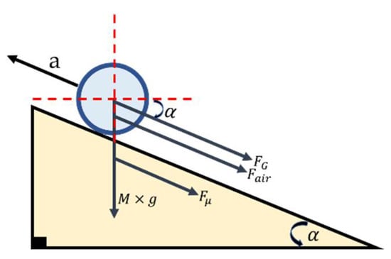
Figure 1.
Vector representation of gradient force (), rolling resistance force (), force due to gravity (M × g) and air resistance force () acting on the wheel when moved on an inclined surface at an angle ‘’.
Here, and represent nominal velocity, number of wheels used and diameter of the wheel, respectively.
2.2. Proposed Working Criteria
Figure 2a,b represent the working criteria for two possible cases. Firstly, for calculating the motor torque when the mobile robot’s load capacity is available (Case I: Motor Selection), and secondly, for calculating the total load capacity when the motor is available (Case II: Motor Available). Two different GUIs were developed using the MATLAB software for both cases. Both cases include the diameter of the wheel and slope angle as input since they depend on the robot dimensions and application irrespective of the availability of a motor.
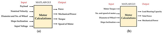
Figure 2.
Inputs and outputs of motor calculation: (a) Case I, when motor is to be selected for given payload; (b) Case II, when motor is available and its payload capacity is to be calculated.
3. Results and Discussion
In this section, first, the graphs for the previously discussed equations are given to represent the change in motor parameters with respect to the change in motor speed. Second, the designed GUIs are presented for the above discussed working criteria along with the results of the motor calculations for both cases.
3.1. Graphical Representation of the Equations
Using a motor load profile to represent the varying speed of the motor from [2], the change in torque and mechanical power with respect to the change in motor speed is represented graphically as shown in Figure 3a–c.
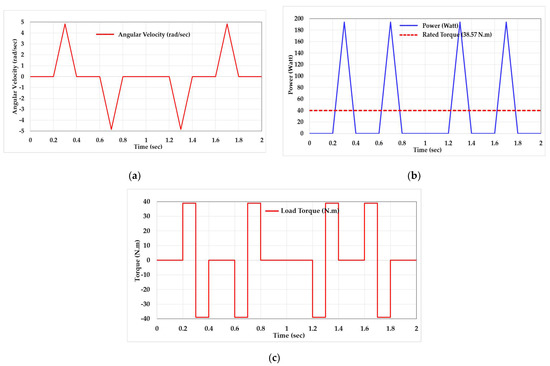
Figure 3.
Motor load parameters (torque and power calculations given in subsequent section): (a) motor load profile with varying angular velocity [2]; (b) change in mechanical power corresponding to change in angular velocity at constant torque of 38.97 N·m; (c) change in motor torque corresponding to change in angular velocity at constant power of 186.89 watts.
For a given motor at a rated torque, another key factor that governs the payload capacity of a mobile robot is the diameter of the wheel. If we increase the diameter of the wheel, the mechanical/tractive power delivered by the motor decreases; see (1) and (4). Consequently, the payload capacity also decreases as represented in Figure 4.
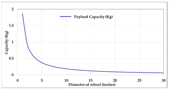
Figure 4.
Relation between diameter of wheel and payload capacity of mobile robot at rated torque.
3.2. Results from Proposed Working Criteria
Using the MATLAB GUI developed from the equations in the previous section, we calculated the motor parameters for a 250 kg mobile robot that is being designed to hold a 35 kg Denso VS-6556 robotic arm. Calculations are given in Figure 5a,b assuming both the cases where the motor is already available and where the payload is already known. The desired speed in Case I was selected to be 0.8 m/s since most heavyweight rovers have a lower speed as discussed in Table 1.
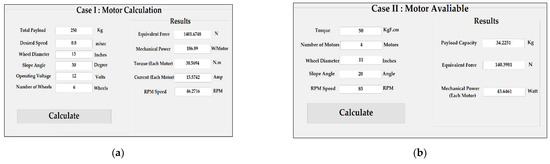
Figure 5.
MATLAB graphical user interface: (a) calculation for Case I, motor is to be selected for given payload; (b) calculations for Case II, motor is available and its payload is to be calculated.

Table 1.
Different mobile robots with their weight and speed.
4. Conclusions
The method presented for the selection of a motor can be used in designing mobile robots with any range of payload. In this regard, the MATLAB GUI was designed for ease of calculation. After the selection of a motor, appropriate wheel sizing is necessary as discussed in the paper. The method is being utilized for selecting the motor for a heavyweight mobile robot with a 35 Kg Denso industrial robotic arm. The future direction of this work includes its extension for the complete design of different parts of a mobile robot by adding several other parameters.
Author Contributions
Conceptualization, A.H.A. and S.M.H.K.; methodology, A.H.A.; software, S.M.H.K. and H.A.P.; validation, A.H.A.; investigation, A.H.A. and S.M.H.K.; writing—original draft preparation, A.H.A.; writing—review and editing, M.A.S., S.M.H.K. and H.K.; supervision, R.U. All authors have read and agreed to the published version of the manuscript.
Funding
This work was supported by the Higher Education Commission of Pakistan under the grant titled, “Establishment of National Centre of Robotic and Automation (DF-1009-31)”.
Institutional Review Board Statement
Not applicable.
Informed Consent Statement
Not applicable.
Data Availability Statement
Not applicable.
Acknowledgments
The authors would like to thank Madiha Akbar from Haptic, Human Robotics and Condition Monitoring Lab for her technical assistance.
Conflicts of Interest
The authors declare no conflict of interest.
References
- Zhang, H.-Y.; Lin, W.-M.; Chen, A.-X. Path Planning for the Mobile Robot: A Review. Symmetry 2018, 10, 450. [Google Scholar] [CrossRef] [Green Version]
- Roos, F.; Johansson, H.; Wikander, J.J.M. Optimal selection of motor and gearhead in mechatronic applications. Mechatronics 2006, 16, 63–72. [Google Scholar] [CrossRef]
- Choi, C.; Jung, S.; Kim, S.; Lee, J.; Choe, T.; Chung, S.; Park, Y. A motor selection technique for designing a manipulator. In Proceedings of the 2007 International Conference on Control, Automation and Systems, Seoul, Korea, 17–20 October 2007. [Google Scholar]
- Cusimano, G.J.M.; Theory, M. Choice of motor and transmission in mechatronic applications: Non-rectangular dynamic range of the drive system. Mech. Mach. Theory 2015, 85, 35–52. [Google Scholar] [CrossRef]
- Ling, Z.; Zhou, L.; Guo, S.; Zhang, Y. Equivalent circuit parameters calculation of induction motor by finite element analysis. IEEE Trans. Magn. 2014, 50, 833–836. [Google Scholar]
- Van de Straete, H.J.; Degezelle, P.; De Schutter, J.; Belmans, R.J. Servo motor selection criterion for mechatronic applications. IEEE Trans. Magn. 1998, 3, 43–50. [Google Scholar] [CrossRef]
- Lyutarevich, A.; Dolinger, S.; Plankov, A. Development of permanent magnet motor calculation technique. In Proceedings of the 2016 2nd International Conference on Industrial Engineering, Applications and Manufacturing (ICIEAM), Chelyabinsk, Russia, 19–20 May 2016. [Google Scholar]
- Gönüllü, M.K. Development of a Mobile Robot Platform to Be Used in Mobile Robot Research. Master’s Thesis, Middle East Technical University, Ankara, Turkey, 2013. [Google Scholar]
- Neobotix Robots. Available online: https://www.neobotix-robots.com/products/mobile-manipulators/mobile-robot-mm-400 (accessed on 25 January 2022).
- Robotnik. Available online: https://robotnik.eu/products/mobile-manipulators/rb-vulcano-en/ (accessed on 25 January 2022).
- NASA Science Mars Exploration Program. Available online: https://mars.nasa.gov/msl/spacecraft/rover/summary/ (accessed on 25 January 2022).
- NASA Science Mars 2020 Mission Perseverance Rover. Available online: https://mars.nasa.gov/mars2020/spacecraft/rover/wheels/ (accessed on 25 January 2022).
Publisher’s Note: MDPI stays neutral with regard to jurisdictional claims in published maps and institutional affiliations. |
© 2022 by the authors. Licensee MDPI, Basel, Switzerland. This article is an open access article distributed under the terms and conditions of the Creative Commons Attribution (CC BY) license (https://creativecommons.org/licenses/by/4.0/).