1. Introduction
The reliability and safety of modern railway infrastructure are fundamental prerequisites for the efficient and uninterrupted operation of rail transport systems. Within this context, overhead line construction (OLC) plays a crucial role as both a load-bearing and power-transmitting system, continuously subjected to a variety of mechanical and environmental influences. In addition to static loads such as self-weight and assembly forces, cyclic effects arise from train operations, wind loads, and the interaction between pantograph and contact wire. These (cyclic) stresses can lead to material fatigue as well as failure and thus represent a key challenge in the design of safety-critical components.
A particularly critical element within the overhead line system is the cantilever support joint, which serves as the structural interface between the mast and cantilever arm, ensuring reliable load transfer throughout the system. In recent decades, aluminium cast alloys—such as EN AC-AlSi7Mg0.3 T6—have gained increasing importance in railway infrastructure applications [
1,
2]. Their favourable properties, including lightweight, good corrosion resistance, and adequate mechanical strength, make them attractive alternatives to traditional steel and cast-iron components. This transition, initiated in the mid-20th century, has enabled significant weight reductions, simplified installation processes, and improved long-term durability of overhead line systems [
3,
4].
Despite these advantages, aluminium cast components exhibit lower material and fatigue strength compared to steel, making them more sensitive to (cyclic) loading conditions. As a result, their operational reliability depends strongly on a detailed understanding of fatigue mechanisms, stress concentrations, and load interactions under realistic service conditions. While existing standards, such as Eurocode 9 [
5,
6] and DIN EN 50119 [
7], provide general guidelines for material selection and structural design, they do not yet offer sufficiently detailed methodologies to reliably demonstrate service lives of 70 years or more for overhead line components.
This gap in current design and approval practices is particularly evident in the assessment of cyclically loaded components such as cantilever joints. While static load-bearing capacity is generally well addressed in existing design approaches, fatigue is often neglected or considered to be of secondary relevance. Consequently, the realistic representation of operational load spectra and their contribution to fatigue damage remains insufficiently addressed. In practice, this leads to design approaches that do not fully reflect actual service conditions and damage mechanisms. Closing this gap is essential not only from a technical perspective but also in light of increasing demands for sustainability, lifecycle optimisation, and infrastructure resilience. Extending the service life of components reduces maintenance efforts, lowers life-cycle costs, and enhances the overall availability and safety of railway systems.
Against this background, this study investigates how the structural performance of aluminium cast cantilever pole brackets can be verified for a target service life of approximately 70 years. The approach follows a target-oriented, application-driven methodology that is closely aligned with industrial practice. Realistic load scenarios, damage mechanisms, and boundary conditions are explicitly considered, rather than relying on purely idealised or academic assumptions. Particular emphasis is placed on integrating fatigue design into established verification concepts that already account for static strength. A combination of advanced material characterisation, optimised component design, experimental validation, and simulation-based methods is used to support the development of a robust and practice-oriented approval concept. In addition, this study identifies limitations in current standards and outlines necessary advancements required to fully exploit the potential of aluminium castings for durable, lightweight, and low-maintenance overhead line infrastructure.
2. Cantilever Joints in Overhead Line Construction (OLC)
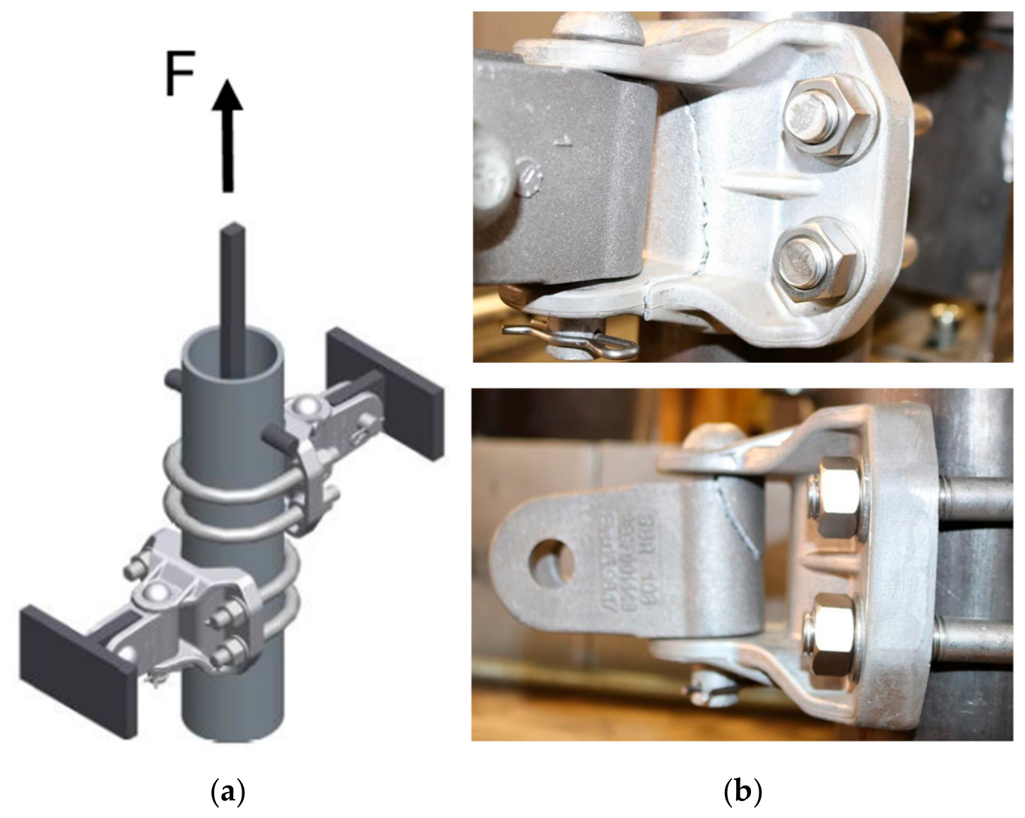
In overhead line systems, the contact wire is supported by the cantilever’s suspension assembly, which is hinge-connected to the mast, allowing movement compensation while ensuring stable and flexible guidance of the contact wire. In this manner, the cantilever pole bracket is a central connecting element, enabling the hinged connection between the mast and cantilever structure (see
Figure 1). Its main function is to carry loads to the mast while allowing movement so that temperature-induced length changes in the contact wire and mechanical influences can be compensated for.
The cantilever pole bracket (Rail Power Systems GmbH, Munich, Germany) used here was a cast component made of EN AC-AlSi7Mg0.3 T6 aluminium alloy, designed for catenary systems in tunnels and open tracks of Re100 (~100 km/h) to Re330 (~300 km/h) classes. It serves a load-bearing and connecting function, attaching two brackets to a suspension mast with two bolts each, forming the interface between mast and cantilever and ensuring safe force transmission (see
Figure 1). With a variable mast diameter of 80–101.6 mm, the cantilever pole bracket allows flexible installation and is a critical safety component of the overhead line system.
According to DIN EN 50119 [
7], the verification of such components is generally performed by mechanical load testing using a quasi-static approach. This means that the governing load cases (e.g., self-weight, wire tension, wind loads) are considered statically, while cyclic effects such as vibrations or fatigue due to wind loads are not explicitly verified but are instead accounted for indirectly through safety factors and load assumptions.
3. Challenges in Structural Verification of Cantilever Pole Brackets in OLC
3.1. Materials
The casting aluminium alloy AlSi7Mg0.3 (EN AC-42100, T6) features a light weight, high strength, corrosion resistance, and good castability, making it particularly suitable for overhead line components such as cantilever structures and pole brackets.
According to the manufacturer’s Inspection Certificate 3.1 (according to EN 10204 [
8]), the material exhibits an ultimate tensile strength (R
m) of 290 MPa, a 0.2% proof stress (R
p,0.2) of 210 MPa, an elongation at fracture of 4%, and a hardness of 90 HB. These properties correspond well with the design strength values recommended by Eurocode 9 [
5] with f
u = 203 MPa, f
o = 147 MPa, and A
50 = 2%. Eurocode 9 also provides explicit guidelines for the static and fatigue design of aluminium structural components, including cast alloys. Despite these advantages, casting defects—including porosity, shrinkage, and inclusions—are unavoidable and contribute to performance variability, particularly under fatigue loading. This necessitates careful consideration during design, assembly, and quality control. Accordingly, the application of bolted cantilever pole brackets in overhead contact line systems and related infrastructure requires meticulous planning, adherence to design standards, and accounting for both material variability and assembly-induced defects/stresses to ensure long-term structural integrity.
3.2. Failure Behaviour Under Bolt Tightening Torque During Assembly
The cantilever pole brackets need to be installed with a bolt tightening torque. To ensure correct assembly and thus to minimise the risk of initial cracks while tightening, the failure behaviour under bolt tightening torque during assembly was investigated through experimental testing. The primary objective was to determine the torque level at which crack initiation or fracture starts.
The specimens were subjected to a stepwise increase in tightening torque up to 200 Nm per bolt. In the first test, no failure or crack initiation was observed. However, the measurements indicate a continuous increase in strain with increasing torque, with the highest values (ε = 2%) occurring in the regions of the lateral arms near the fillet radius. These areas can therefore be identified as the most critical zones with respect to stress concentration. In the second test, a different behaviour was observed. The specimen withstood tightening torques of up to 170 Nm without any visible damage. A further increase in torque led to fracture. The crack initiated at the edge of a lateral arm, precisely in the region previously identified as critical. Notably, a pronounced and abrupt increase in strain was recorded at this location immediately prior to failure, reaching a maximum value of ε = 3.34%.
To prevent cracking or any pre-damage, the maximum tightening torque for the cantilever pole bracket during assembly was limited to 70 Nm with strain values below ε = 0.4% and thus far below cracks/failure. This corresponds to a two-stage, and consequently very efficient, assembly.
3.3. Pull-Out Tests
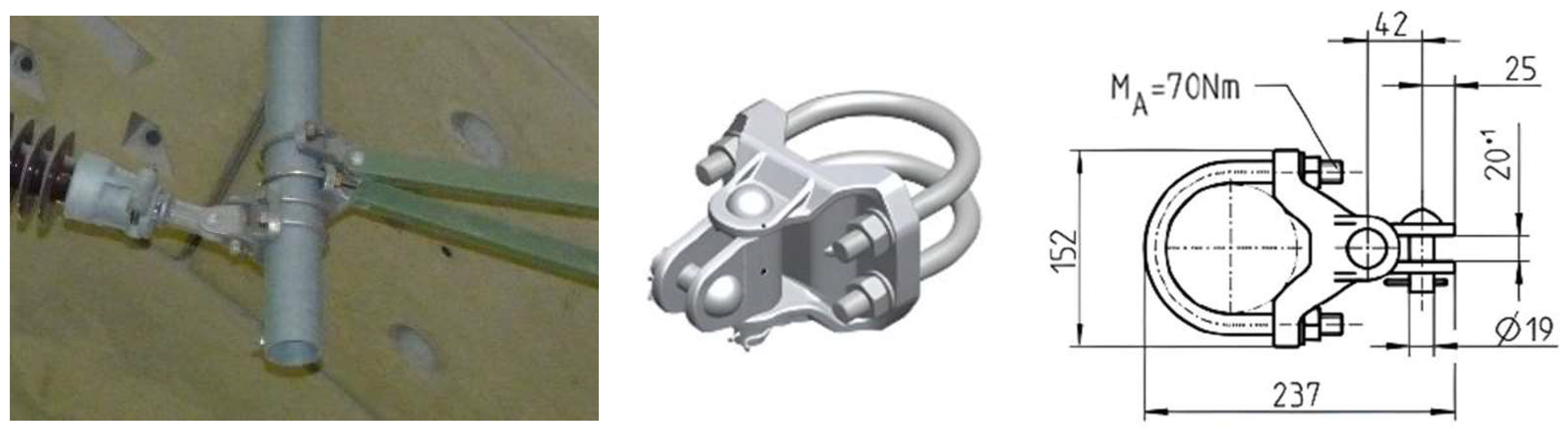
In overhead line construction, cantilever pole brackets are used, among other applications, for the fixation and load transfer between components, where the reliable transmission of tensile forces without relative slip is of particular importance. Against this background, pull-out tests were conducted to investigate the load-bearing and failure behaviour of aluminium pole brackets under a defined bolt tightening torque of 70 Nm (see
Section 3.1). The pole bracket was held in position while the bolt on the tube was tightened using a mounting fixture. Subsequently, a tensile force was applied to the tube. During this process, the force was measured up to the point at which the tube began to slip (see
Figure 2).
The test results show that, in all experiments, no relative slip between the cantilever pole brackets and the tube occurred. Load transfer was therefore achieved entirely by frictional resistance, indicating that the connection can be classified as slip-resistant for the selected tightening torque. With increasing load, only deformations of the components were observed.
Failure of the specimens occurred in all cases due to material fracture, either in the joints or within the saddle section of the lower pole brackets. The maximum loads achieved for the respective test setup with two pole brackets ranged between 24.8 kN and 30.5 kN per pole bracket.
Overall, the results demonstrate that the load-bearing capacity of the investigated connection is not governed by potential slip, but rather by the strength of the components themselves. The clamping effect resulting from the applied tightening torque of 70 Nm is therefore sufficient to prevent slipping, while structural failure is the governing mechanism for the maximum load capacity.
3.4. Tensile Capacity Under Varying Bolt Tightening Torque
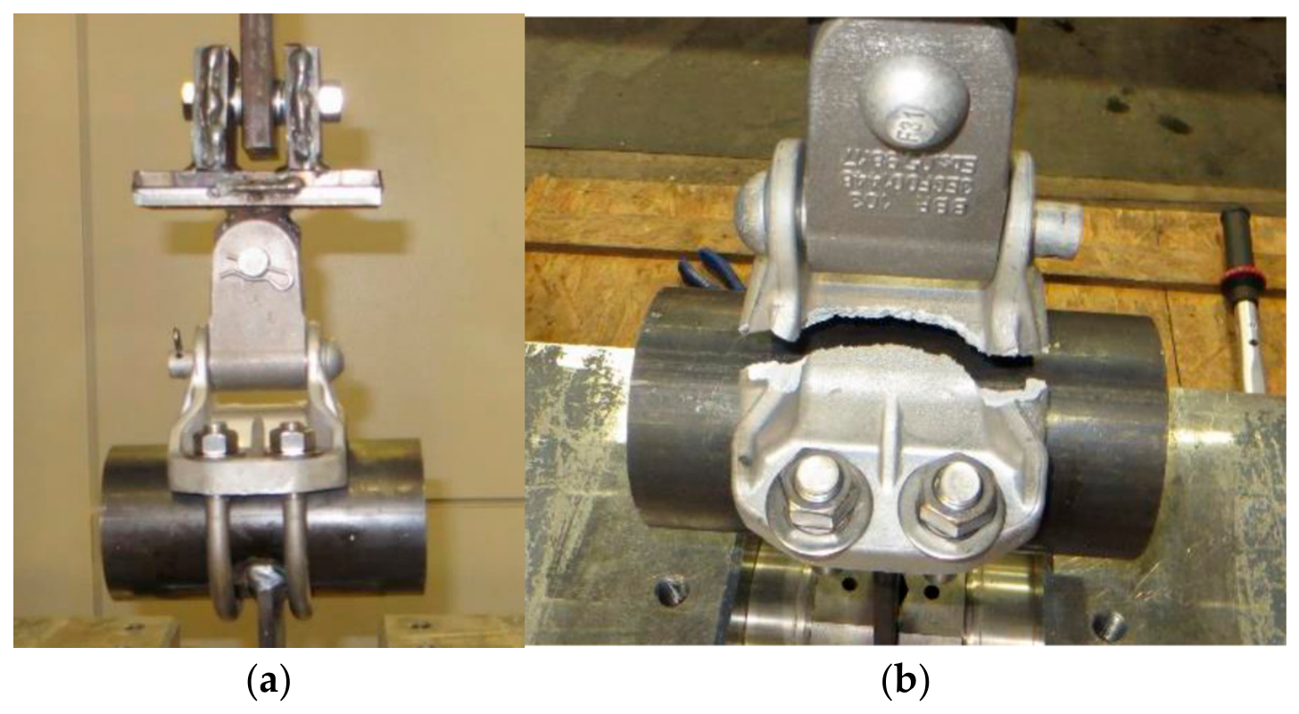
In the next step, the maximum tensile capacity of four aluminium cantilever pole brackets was evaluated under bolt tightening torques of 70 Nm (see
Figure 3). These results were then compared with values from internal experiments conducted with a bolt tightening torque of 135 Nm. The primary objective was to assess whether the applied tightening torque influences the load-bearing capacity.
The four tensile tests revealed failure in only one case: the first specimen fractured at the saddle region of the pole bracket at a load of 96 kN. The remaining three specimens reached maximum tensile forces of 75.1 kN and 93.6 kN (failure of hinge) and 99.9 kN (failure of bolt).
Compared to previous tests conducted at a higher tightening torque of 135 Nm, which yielded tensile forces of approximately 80–85 kN, the current results are partially higher. However, this comparison is of limited significance due to differences in test conditions, particularly with regard to the larger tube diameter used in the current tests (100 mm instead of 80 mm).
A key observation is that no general reduction in load-bearing capacity was observed due to the reduced tightening torque. Overall, the data suggest that the tested cantilever pole brackets maintain high tensile capacity under both assembly conditions.
It has to be noted that, according to the latest analysis conducted by RPS, the real maximum tensile loads amount to 8.36 kN, whereas previous test reports assumed values of 9.5 kN. These forces indeed represent operational loads. In accordance with DIN EN 50119, the component under investigation is required to withstand this load 2.5 times during testing.
3.5. Fatigue
As mentioned above, according to DIN EN 50119, the verification of OLC-Components is generally carried out through mechanical load testing based on a quasi-static approach. However, structures next to (high-speed) train lines are subjected to cyclic loads based on vibrations from the passing trains and wind loads.
Therefore, first, the dynamic interaction between the pantograph and overhead line was simulated using TracFeed
® CATMOS
® (Version: 2025), considering trains reaching 250 km/h. Key outputs include the vertical pantograph trajectory, contact force, and vertical displacements of selected cantilever side holders. The trajectory remained stable, with minor fluctuations (Δ = 38 mm) and contact forces varied between 46.3 N and 229.7 N, staying within DIN EN 50119 limits (μ ± 3σ) [
9].
These quasi-static simulations provide insight into cantilever–pole bracket behaviour but do not capture the cyclic stresses induced by high-speed trains and wind. At the same time, field observations show progressive wear and damage and thus highlight the importance of fatigue, especially for cast aluminium alloys susceptible to internal defects like porosity and inclusions.
Fatigue evaluation of cast alloys according to EC 9 [
6] requires a porosity-dependent assessment for cast alloys:
- -
Low-porosity components: maximum pore diameters of 0.2–0.5 mm, with a corresponding fatigue strength reduction in ΔσC ≈ 50–70 MPa. These pores require specialised non-destructive testing (NDT) methods, such as radiography (RT), for detection.
- -
Medium-porosity components: pores with diameters of 1.5–9.5 mm, achieving ΔσC ≈ 30–50 MPa. These pores can typically be detected using ultrasonic testing (UT).
- -
High-porosity or porosity-rich castings: pores larger than 1.5 mm, with ΔσC ≈ 20–30 MPa. Such pores are generally detectable through visual inspection.
This confirms that internal material quality, not geometry alone, governs fatigue performance, and dedicated fatigue testing—precisely as performed here—is essential to meet Eurocode 9 [
5] requirements and ensure long-term structural safety.
For the pole bracket, however, no standard detail category exists in the Eurocode 9 [
5] catalogue, requiring special treatment. Consequently, the code mandates either the use of a conservative detail class or an experimentally determined SN-curve. This is why, as a second step, fatigue tests with round specimens as well as with cantilever pole brackets themselves are performed, currently ongoing, and expected to be completed in the coming months.
4. Conclusions and Outlook
This study demonstrates that aluminium cast cantilever pole brackets (EN AC-42100, T6) offer a reliable and lightweight alternative to traditional steel components in overhead line construction, combining sufficient static and quasi-static load-bearing capacity with corrosion resistance and ease of assembly. Experimental investigations, including pull-out and tensile tests under different bolt tightening torques (70 Nm and 135 Nm), confirmed that the primary failure mode is material fracture rather than connection slip, and no general reduction in tensile capacity was observed under reduced torque.
However, the quasi-static verification prescribed by DIN EN 50119 [
7] does not account for cyclic loads arising from high-speed trains, wind, or temperature variations. Simulations of pantograph–overhead line interaction indicated stable trajectories and acceptable contact forces, but field observations and material sensitivity reveal that fatigue is the governing mechanism for long-term performance, particularly for cast aluminium alloys susceptible to porosity and internal defects. According to Eurocode 9 [
5], the absence of a standard detail category for the pole bracket requires either the adoption of a conservative detail class or an experimentally determined SN-curve. In response, dedicated fatigue tests with round specimens and full-scale cantilever pole brackets are currently being performed, providing the necessary data to establish fatigue limits and ensure long-term operational safety.



 ,
,