1. Introduction
Transcutaneous electrical nerve stimulation (TENS) is a method of electrical stimulation, which primarily aims to provide pain relief. It works on the principle of exciting the sensory nerves, and stimulating the pain gate mechanism. TENS device is a safer mode of treatment without any side effects [
1]. TENS knee brace provides pain relief and muscle relaxation by stimulating the muscles and motor points, enabling better blood circulations. This research work utilized the concept of TENS therapy for pain and muscle relaxation. Using this concept, a handheld TENS module device was developed using textile electrodes, unlike conventional carbon rubber and hydrogel electrodes.
An electric circuit integrated with MOSFET was developed for the generation of electric pulses, which was controlled via a microcontroller. This helped in the generation of symmetrical biphasic waveforms. The frequency and pulse width of waveforms were adjusted by changing the variables in the microcontroller program. The intensity of electric pulses was adjusted by varying the input voltage.
TENS modules used in kneecaps have been found to be efficient, noninvasive, and with no side effects for overcoming chronic pains. However, the existing modules are found to be uncomfortable. This was explored further to realize the shortcomings of the current existing electrodes used in TENS modules, such as hydrogels and carbon rubber electrodes. Three types of frequency modes are used in TENS. (1) High frequency (90–130 Hz), which initiates the pain gate mechanism by activating the A beta sensory nerves thus reducing the transmission of pain stimulus to reach the brain (2) Low frequency (2–5 Hz), which activates the opioid mechanism and causes the release of an endogenous opiate in spinal cord. This acts as a pain killer and helps in relieving the pain [
2]. (3) Burst frequency is the third variant, which is a combination of high and low frequencies [
3]. Any electric stimulation using the skin surface electrode with the intention of stimulating nerves that provide symptomatic pain relief can be referred to as TENS [
4]. The burst frequency activates both mechanisms and provides an effective result. Electrodes are used to conduct these electric pulses into the body. The positioning of the electrodes is important. Electric stimulation works effectively if placed appropriately at the required location of the body. It should be near the location where the highest intensity of pain exists and near the nerve trunk trigger position in order to block the signal’s transmission to the brain. Notably, the electrode needs to be attached to the proper dermatome.
Textile electrodes were developed to overcome the existing drawbacks of conventional electrodes using conductive fabric, as well as integrating conductive yarns through knitting and embroidery. Four different conductive fabrics were selected for the development of textile electrodes, which resulted in four different kneecaps as the final prototype. The final testing and user feedback were considered to evaluate the performance of the TENS module and textile electrode performance.
2. Materials and Methods
2.1. TENS Frequency
Herein, it is possible to give a low frequency range or high frequency range, depending on the end user’s requirements, although the present study has utilized the burst frequency methodology for the TENS module. In addition, the module can be controlled via a microcontroller.
2.2. Comparative Analysis
A comparative analysis was conducted by studying the commercially existing TENS products while considering the electrode. The summary of same is provided in
Table 1. The textile electrodes were found to overcome major drawbacks of the conventional electrodes. One shortcoming of textile electrode is its reduction in conductivity when dry, which states that wet electrodes will be more comfortable than dry electrodes [
5,
6]. In addition, they are found to be durable, washable, breathable, and flexible [
7]. Therefore, the textile electrode was selected for the study.
2.3. Electrodes
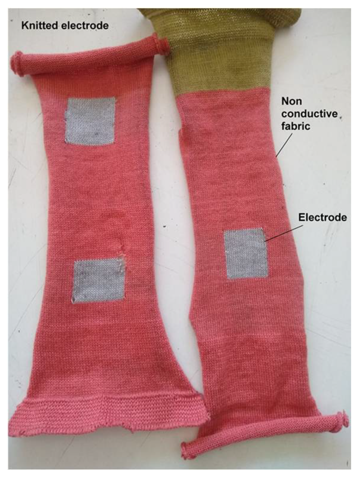
Three methods were used to manufacture the textile electrodes. First, the electrode was developed by knitting using conductive yarns integrated with nonconductive yarns. Second, the conductive yarn was embroidered to make the fabric conductive and utilize it as an electrode. Finally, the conductive coated fabric was used to develop the textile electrode. Based on the comparative analysis one of the method was selected for further studies.
2.3.1. Conductive Yarn Knitted Electrode
Conductive yarns are used to create a 1 × 1 square size patch knitted with nonconductive yarn. A single jersey (10 gauge fabric) is knitted in a hand flat machine. The conductive yarn used was a blend of 20% stainless steel and 80% polyester, of English Count (Ne) 28/2. The wales per inch (wpi) is 19 and the courses per inch (cpi) is 21 (
Figure 1).
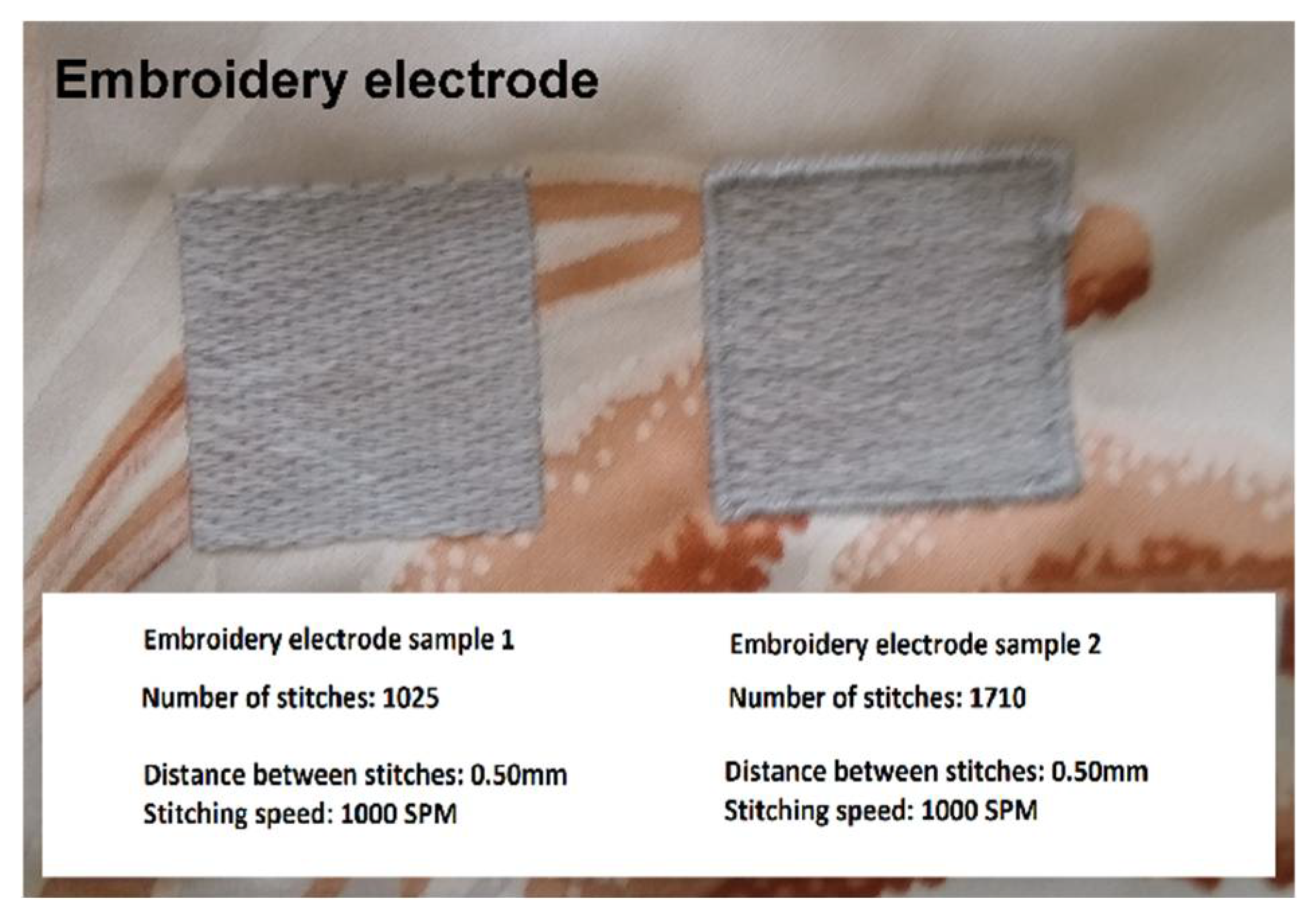
2.3.2. Conductive Yarn Embroidered Electrode
Here, the conductive yarn (20% stainless steel and 80% polyester) of English count (N
e) 28/2 was used for embroidery. Two 1 × 1 square inch shape patches were embroidered on a 100% polyester base fabric. The embroidery machine speed was 1000 stitches per minute (SPM) and the number of stitches per square inch was 1025 (indicates less density) and 1710 (indicates more density), respectively. Both patches were tested separately, but gave similar results. Images of both the patches are given in
Figure 2.
2.3.3. Fabric with Conductive Coating
This textile electrode was constructed by a conductive fabric patch with a silver coating of 99.9%. The patch was attached to the Velcro strap, as shown in
Figure 3.
By improving the conductive properties of textile material, the electrode impedance can be reduced, thus improving polarizability. This further increases in conductivity, which leads to an improvement in the efficiency of TENS module [
8].
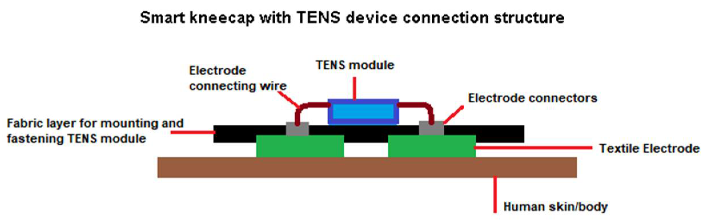
2.4. Prototype Development
The prototype consists of a TENS module with textile electrodes attached to the kneecap. TENS module is connected to the electrodes in the kneecap using wires and a metal snap button. These kneecaps can be worn on the knee. In this way, electric pulses generated by the TENS module will be transferred to the skin via electrodes. A schematic representation of the module is shown in
Figure 4.
2.4.1. Final Textile Electrodes Development
The knitted textile electrode, prepared through knitting of the conductive yarn, was found to be uncomfortable during testing due to irritation and a tingling effect. Furthermore, both sides of the electrode were exposed. As a result, this led to the chance of experiencing an electrical pulse on the external side. Moreover, it involved the high cost of manufacturing.
The textile electrode, prepared through conductive yarn embroidery, was found to be aesthetically appealing with a softer feel and lower manufacturing cost. However, irritation and a tingling effect were reported, as well. Furthermore, with repetitive and prolonged usage, the chances of fraying around the edges of the embroidered conductive yarn were anticipated.
Herein, it was observed that conductive coated fabric patches were the most efficient and suitable textile electrode among all of the textile electrodes developed. Therefore, this category of textile electrode was selected for further prototype development. Four different conductive coated fabrics were sourced for developing the textile electrodes. The commercial names have been replaced and coded as brands P, Q, R, S for confidentiality. The specification and properties of these fabrics are furnished in
Table 2. The sample textile electrode given in
Figure 3 was prepared using the ‘P’ fabric.
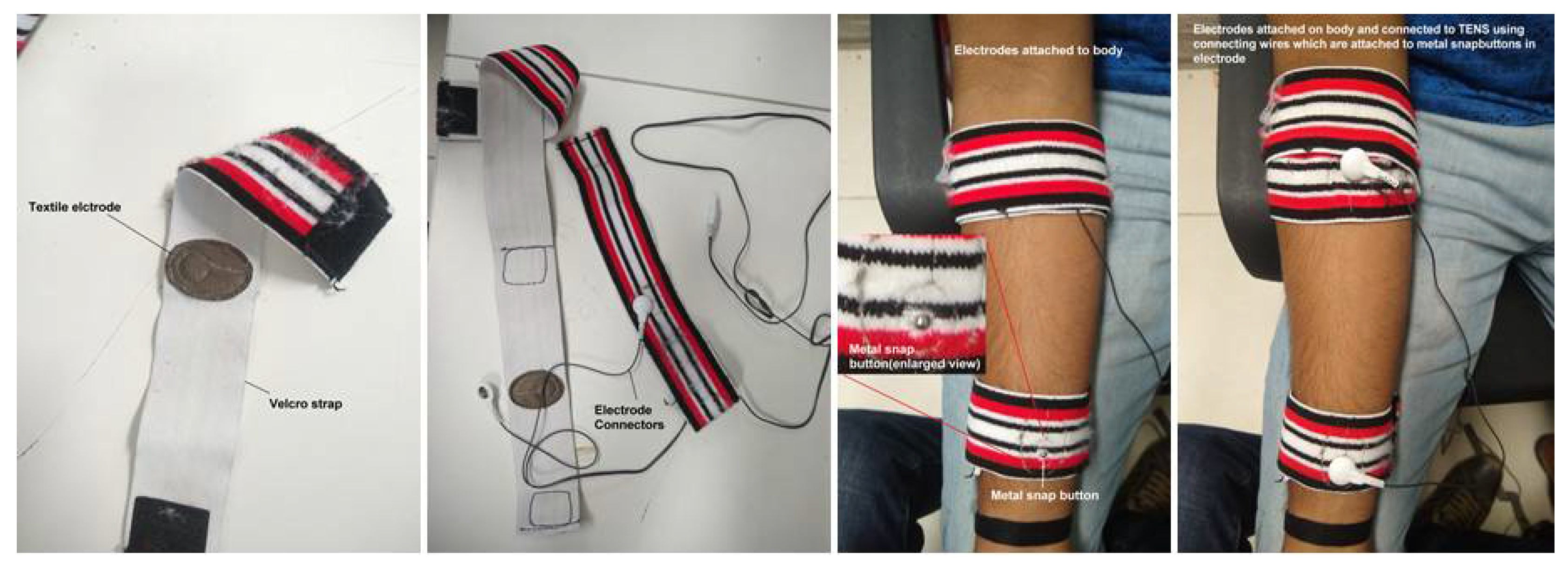
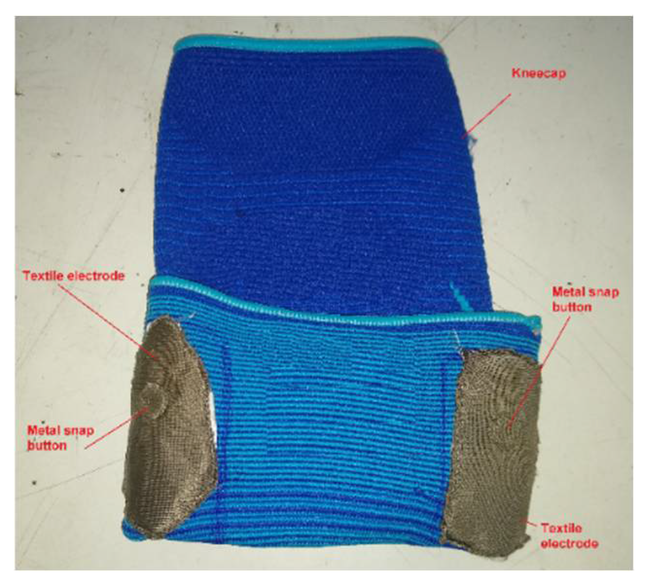
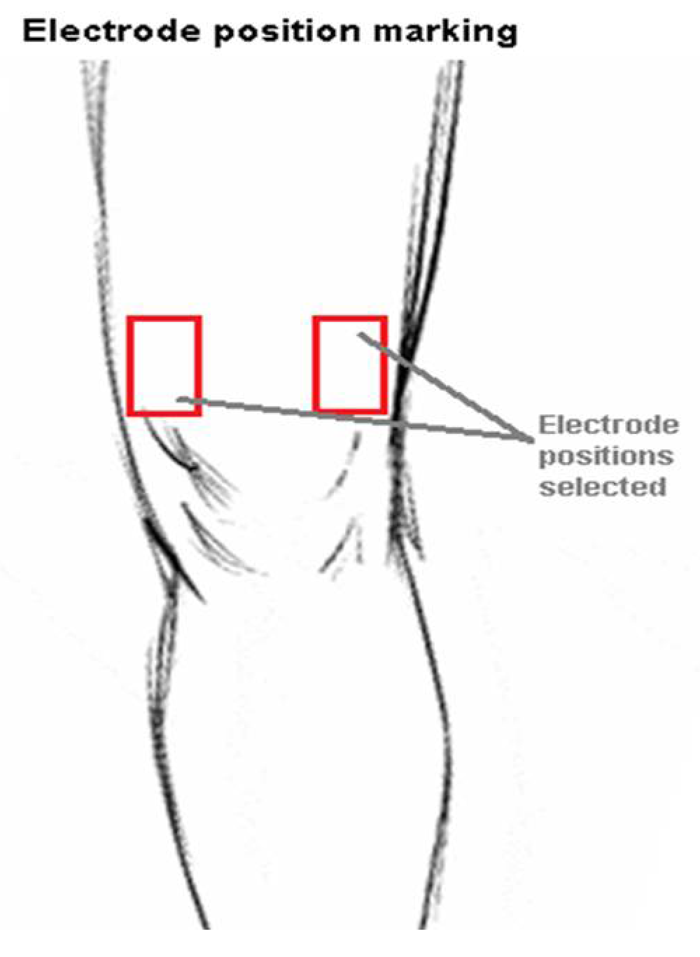
The fabrics were cut into rectangular pieces (size 7 × 4 cm) and attached as a double layer to the kneecap in suitable positions. The metal snap button was used to connect the electrode with the external wires. Positions were selected near the motor points located on the upper side of the knee (
Figure 5). These electrodes were attached to the respective positions in the kneecap (
Figure 6). A Velcro strap was attached to the external side of the kneecap, which can be wrapped around the kneecap for better fastening of electrodes. Similarly, all of the four fabric patches were attached to different kneecaps resulting in four variants, as shown in
Figure 7.
2.4.2. TENS Module Development
A MOSFET switching circuit that works on the H-bridge concept was used for electric pulse generation, which was controlled through an Arduino Uno microcontroller. The frequency and pulse width were adjusted through microcontroller programming. The power supply was drawn from a rechargeable 3.3 V LG MJ1 18650 3500 mAh cell, which was amplified using a voltage booster circuit through LD38050 PU IC, with an amplifying voltage from 0 to 56 V. This variable defines the intensity of the electric pulses. The voltage applied to the microcontroller was regulated to 3.3 V using the voltage regulator circuit—LM25775 IC. The current flowing to the body through the electrodes was controlled using a current limiter circuit developed using LM317T IC. It was used to limit the flow of current into the body within a permissible range. The printed circuit board was prepared based on the designed circuit. The assembly was placed in a customized 3D printed case. The components of the module are shown in
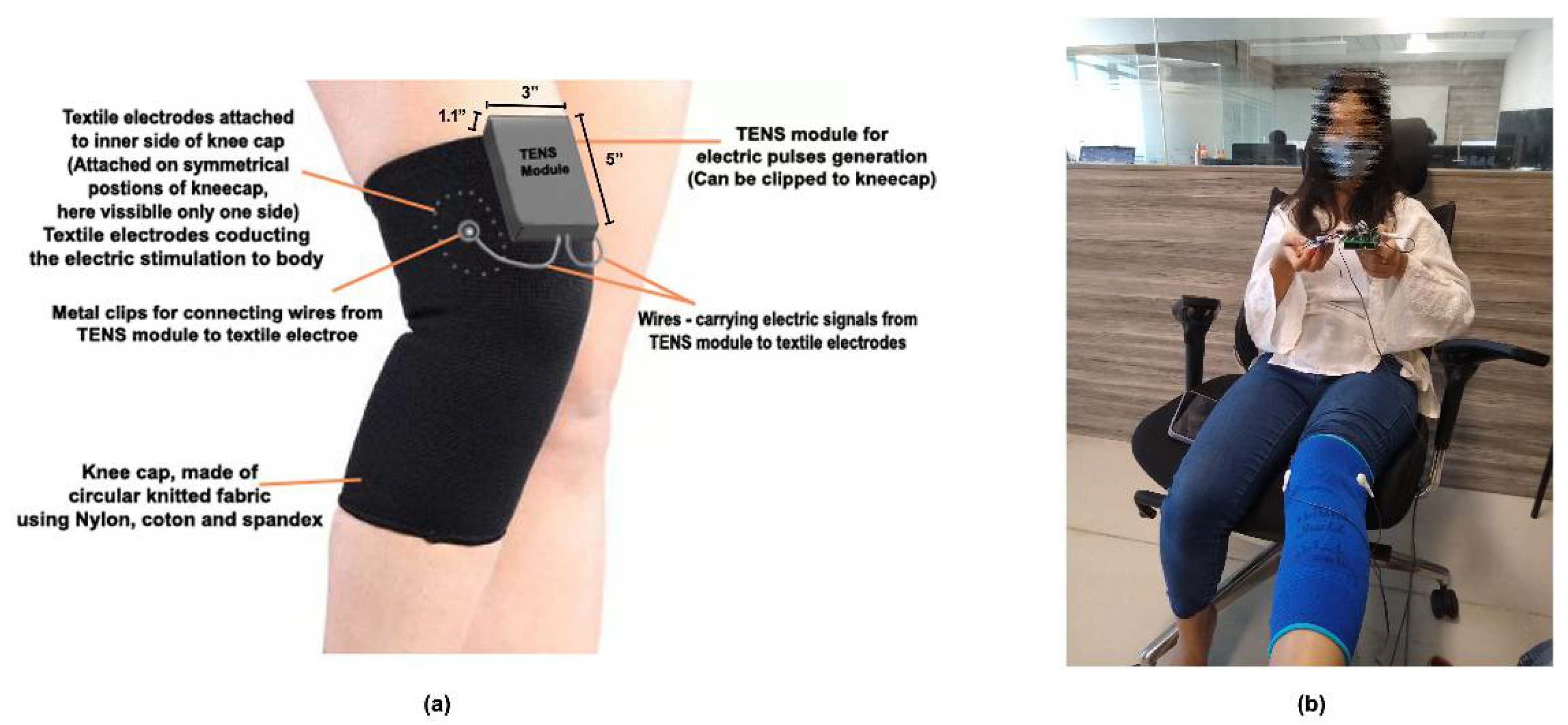
Figure 8. A schematic representation of TENS module and kneecap on the knee are shown in
Figure 9a and the kneecap worn on the knee and TENS module held in hand are shown in
Figure 9b.
The developed TENS module was compared with two other brands of TENS modules, marked as brands X and Y for confidentiality. The user feedback and average rating were used for the evaluation.
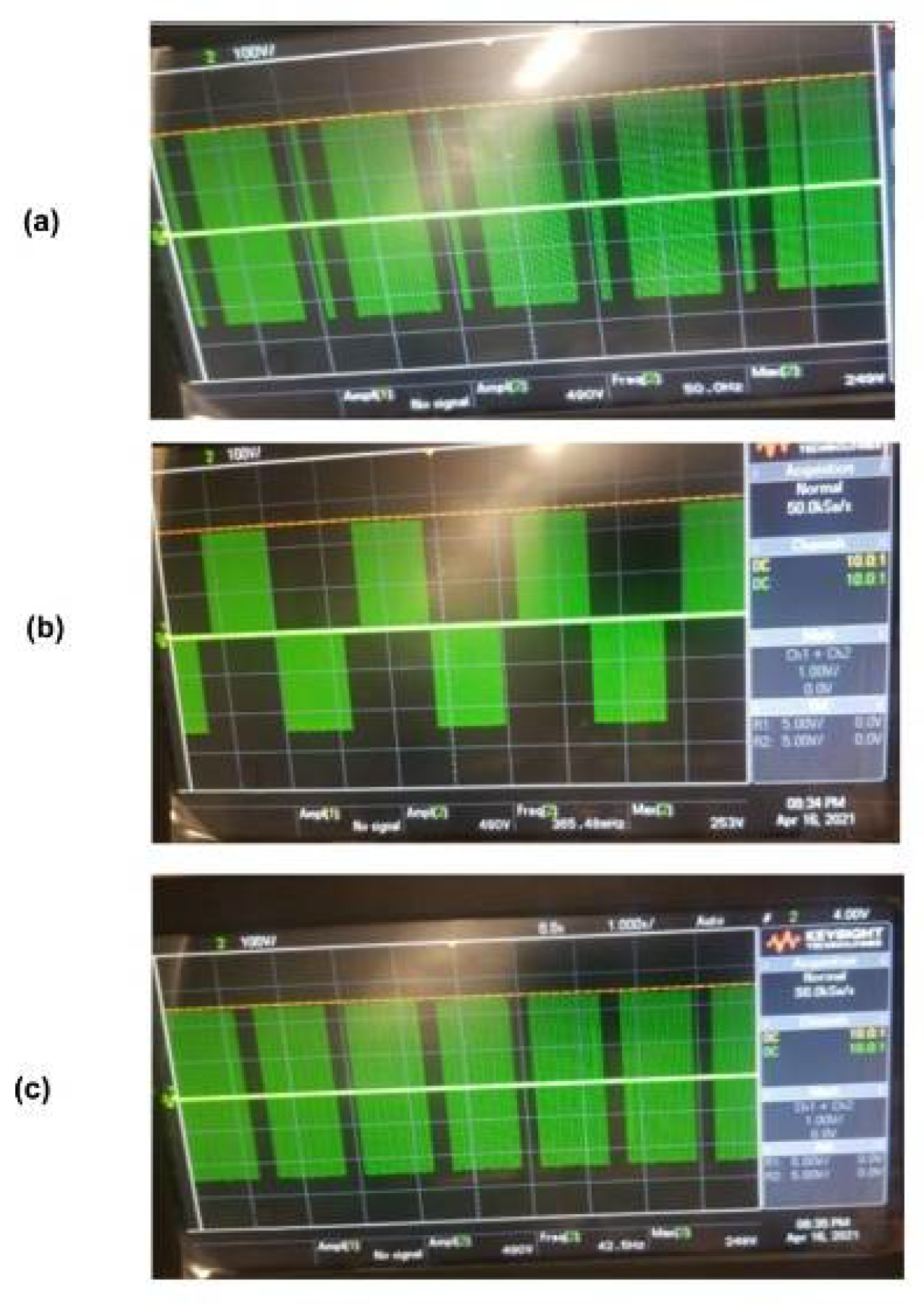
Output electric pulses were passed through the electrodes to the human body. Three different waveforms (
Figure 10) were selected. Different burst waveforms were created, which could be modified for the attainment of different comforts and feels, depending on the user. The waveform specifications are presented in
Table 3.
3. Results and Discussion
3.1. Testing
The smart kneecap with electric stimulation using the textile electrode was successfully developed, based on this study’s objective. The developed circuit was able to generate a perfect symmetric waveform using the switching circuit and microcontroller. Three burst waveforms of varying frequencies and pulse width (
Figure 10) were generated and studied. Resistance of the textile electrode was found to be in the range of 0.4 to 2.1 ohm. The resistance value for the case of TENS with the hydrogel and carbon rubber as an electrode was found to be in mega ohm range. Therefore, the textile electrode exhibited higher efficiency for the TENS module. Notably, it was observed that the textile electrode required a voltage range of 20–25 V for the stimulation, which was in the range of 50–60 V in the case of hydrogel or carbon rubber electrode.
Figure 11 presents the graph with average values of electric intensities for textile and hydrogel electrodes during the stimulation steps. Textile electrodes were found to be more suitable as an electrode in the TENS module.
3.2. Feedback from Subjects
The voltages required for textile, hydrogel, and carbon rubber electrodes were analyzed. Typically, this is stated as the intensity of input power of electric pulses, which is required for the user to feel an effective stimulation. The input voltage requirements were compared among the textile electrodes and other conventional electrodes. The underlying challenge was the effect of individual user’s skin impedance and their sense to electric stimulations. Therefore, a comparison of electrodes was conducted with respect to the voltage range, which is effective and comfortable to each individual. As a result, a comparison of all three types of electrodes (textile, hydrogel, and carbon rubber), was conducted for the individual user for the input voltage specific to each of them.
Feedbacks were collected from 20 users (human subjects). They were advised to sense the stimulation for a specific time of exposure for all the three TENS modules without conveying the brands/category. The feedback was collected on the basis of comfort, skin irritation, and sensitivity to electric stimulation. The developed module received better acceptability with the highest average feedback rating of 7.77 (out of 10). Furthermore, the four textile electrodes, prepared by the conductive fabrics from brands P, Q, R, and S, were also tested using subjective feedback. Brands P and Q obtained an average rating of 7.5, while brands R and S received an average rating of 3.5 and 2.5, respectively (out of 10).
4. Conclusions
In this research project, a smart kneecap integrated with a textile electrode-based TENS module was successfully developed. The electrodes were attached to the kneecap, which resulted in a wearable device. This study affirmed that a wide range of applications of conductive fabrics and textile electrodes are wellness-related wearable products. The developed TENS module was portable in handheld form or attached to the kneecap. In addition, it can operate at lower voltage and power, thus enabling a longer battery life when compared with hydrogel and carbon rubber electrodes. Symmetrical, stable waveforms, as well as smooth textile electrodes can lead to a better comfort level during the electric stimulation process on users (subjects).
As a future scope of this research project, a more compact structure could be attempted for the development of TENS module using a self-powered module integrated with a smaller form factor of microcontrollers. In response to this, the microcontrollers could be connected via Bluetooth technology through a mobile application for an interactive and remote operation.
Author Contributions
This research article was conducted by J.V.R., as part of his research project for the course Master of Fashion technology from National Institute of Fashion Technology, New Delhi. The research was conducted under the supervision of P.J., National Institute of Fashion Technology, New Delhi and R.T., National Institute of Fashion Technology Mumbai. All authors have read and agreed to the published version of the manuscript.
Funding
Financial support for this research was provided by Fupro Innovation Pvt. Ltd.
Institutional Review Board Statement
Not applicable.
Informed Consent Statement
Not applicable.
Acknowledgments
The authors acknowledge the opportunity provided to carry out the research work at Fupro Innovation Pvt. Ltd., an Indian start-up under the incubation of Tynor Orthotics Pvt. Ltd.
Conflicts of Interest
The authors declare no conflict of interest.
References
- Jones, I.; Johnson, M.I. Transcutaneous electrical nerve stimulation. Contin. Educ. Anaesth. Crit. Care Pain 2009, 9, 130–135. [Google Scholar] [CrossRef] [Green Version]
- Watson, T. Transcutaneous Electrical Nerve Stimulation (TENS). Physiopedia. Available online: https://www.physio-pedia.com/Transcutaneous_Electrical_Nerve_Stimulation_(TENS) (accessed on 4 March 2022).
- Singh, J. Textbook of Electrotherapy, 3rd ed.; Jaypee Brothers Medical Publishers: New Delhi, India, 2012. [Google Scholar]
- Vance, C.G.; Dailey, D.L.; Rakel, B.A.; Sluka, K.A. Using TENS for pain control: The state of the evidence. Pain Manag. 2014, 4, 197–209. [Google Scholar] [CrossRef] [PubMed] [Green Version]
- Zhou, H.; Lu, Y.; Chen, W.; Wu, Z.; Zou, H.; Krundel, L.; Li, G. Stimulating the Comfort of Textile Electrodes in Wearable Neuromuscular Electrical Stimulation. Sensors 2015, 15, 17241–17257. [Google Scholar] [CrossRef] [PubMed]
- Erdem, D.; Yesilpinar, S.; Senol, Y. Design of TENS electrodes using conductive yarn. Int. J. Cloth. Sci. Technol. 2016, 28, 311–318. [Google Scholar] [CrossRef]
- Yapici, M.K.; Alkhidir, T.; Samad, Y.A.; Liao, K. Graphene-clad textile electrodes for electrocardiogram monitoring. Sens. Actuators. B Chem. 2015, 221, 1469–1474. [Google Scholar] [CrossRef]
- Márquez Ruiz, J.C. On the Feasibility of Using Textile Electrodes for Electrical Bioimpedance Measurements. Ph.D. Thesis, KTH–Royal Institute of Technology, Stockholm, Sweden, 2011. [Google Scholar]
| Publisher’s Note: MDPI stays neutral with regard to jurisdictional claims in published maps and institutional affiliations. |
© 2022 by the authors. Licensee MDPI, Basel, Switzerland. This article is an open access article distributed under the terms and conditions of the Creative Commons Attribution (CC BY) license (https://creativecommons.org/licenses/by/4.0/).


