
Adaptive Sliding Mode Control Improved by Fuzzy-PI Controller: Applied to Magnetic Levitation System †


1
LRPCSI Laboratory Skikda, Université 20 Aout 1955 Skikda, Skikda 21000, Algeria
2
Automatic Laboratory of Skikda, Université 20 Aout 1955 Skikda, Skikda 21000, Algeria
*
Author to whom correspondence should be addressed.
†
Presented at the 1st International Conference on Computational Engineering and Intelligent Systems, Online, 10–12 December 2021.
Eng. Proc. 2022, 14(1), 14; https://doi.org/10.3390/engproc2022014014
Published: 8 February 2022
(This article belongs to the Proceedings of The 1st International Conference on Computational Engineering and Intelligent Systems)
Abstract
:This study mainly concerns the use of Fuzzy-PI adaptive sliding control (Fuzzy-ASMC) to force the stat space of MAGLEV to track a desired trajectory. The usage of adaptive sliding mode control allows the MAGLEV to operate in an uncertain environment and in the presence of external disturbances. The Fuzzy-PI schema is designed to improve the performance of adaptive sliding mode control and reduce the main drawback caused by the discontinuous term of this method, which is the well-known chattering phenomenon. The results of our study prove the effectiveness of the proposed approach in achieving desired performances.
1. Introduction
Magnetic levitation (MAGLEV) systems have gained popularity because of their practical importance in many engineering fields, such as high-speed passenger trains, frictionless bearings, the centrifugation of nuclear reactors, levitated wind tunnel models, magnetic suspension and balance systems, the vibration isolation of sensitive machinery, the levitation of molten metal in induction furnaces and heart pumps, etc. [1]. The model that describes the dynamics of MAGLEV is the highly unstable, nonlinear state space model.
One of the most elegant strategies in the field of control is adaptive control. This method can treat systems with parametric variation when the operating conditions are degraded; however, this approach fails if they are affected by external perturbation later.
Several studies have been developed in the field of the control of non-linear systems, for example, adaptive control (Isidori 1989 [2], Slotine and Li 1991 [3]). However, sliding mode control (SMC) proposed by Utkin 1977 [4] has been the most popular approach for use in controlling uncertain, non-linear, single-input, single-output SISO systems (Drakunov and Utkin 1992 [5], Slotine 1984, 1987 [6,7]) because of its simplicity and its robustness against external disturbances. Sliding mode control is part of the family of controllers with variable structures, which can deal with uncertainties and unmodeled dynamics, insensitivity to external load disturbances, stability and a fast dynamic response [8,9,10]. The principle of this method is to constrain the trajectories of a system to achieve a given sliding surface and then stay there. However, in practice, control by sliding mode induced high-frequency switching known as chattering. These switches can excite unwanted dynamics that risk destabilizing, damaging or even destroying the system under study.
Many studies have proposed methods of dealing with chattering phenomena, which include replacing the sgn function by the saturation function or sigmoid function [11] and high-order sliding mode control, whose principle is to reject the discontinuities in higher derivatives of a system input [12,13]. Another method is to use an asymptotic observer via sliding mode, the aim of which is to generate ideal sliding modes in an auxiliary observation loop so that this observer loop does not integrate any unmolded dynamics [14].
Among these different proposed schemes, the Fuzzy-PI strategy has shown its effectiveness in alleviating the chattering phenomenon due to its smoothness, speed and the ease of implementation. Motivated by the above-mentioned discussion, we propose in this paper a new architecture control design based in adaptive sliding mode control (ASMC) to force the MAGLEV’s to track a given desired trajectory, and the second part combination between Fuzzy-PI controller and ASMC controller used to reduce the chattering phenomenon caused by the dis-continuous term of the ASMC.
2. System Description
The dynamic model for the MAGLEV system as given as [15]:
where p is the ball’s position, w denotes the ball’s velocity, i is the current in the electromagnet, V denotes the applied voltage, R and L are the coil’s resistance and inductance, respectively, g is the gravitational constant, Q denotes magnetic force constant and m is the mass of the levitated ball.
The inductance L is assumed to be the nonlinear function of the ball’s position p and is approximated as:
where L1 is a system parameter determined by the electromagnet coil inductance. Let us define x1 = p, x2 = w, x3 = i and u = V and let us state that the vector is x = (x1 x2 x3)T; the state space model of the MAGLEV system can be expressed as [15]:
3. Problem Formulation and Controller Design
3.1. Problem Formulation
The solution to the MAGLEV control problem is initiated by considering the nonlinear change of coordinates as follows:
Assuming xd = (x1d, 0, x1d,) the dynamic model of the MAGLEV with external disturbance d(t) in a new coordinate system can be re-written as [16]:
where f(ξ) and g(ξ) are given by:
Consequently, the control objective is now modified to design the control input u, so that the closed loop system (5) states (ξ1, ξ2, ξ3) converge to zero in finite time under the presence of disturbance d(t).
After this, with some development in Equation (6), system (5) becomes:
where and are given by:
where are given by:
3.2. Controller Design
Considering the following sliding surface:
where λ is a positive constant, n is the order of system and e(t) = ξ1 = x1 − x1d is tracking error.
Given that n = 3rd sliding, this becomes:
The derivative of sliding surface can be formulated as:
Note that in the conventional sliding mode control for system (5), the design of the control system will be as follows [5]:
where K is a positive constant, and ueq and us are the equivalent control vector and the switching part of the control. sgn is the sign function defined by:
Now, let us design the control law for system (7) under the presence of parametric uncertainties and perturbation.
If we consider the following Lyapunov candidate function:
where:
where denotes the estimations used for uncertain terms , is the estimation error and denotes positive constants. After carrying out some mathematical manipulations, the derivative of the candidate Lyapunov function can be obtained as:
Assigning parameter update rules as:
where D = max(d(t)). Equation (17) turns out to be:
The time derivative of the Lyapunov function defined in (15) is given in (22). Note that the function in (22) is negative semi-definite, ensuring the stability of the dynamical system given by (11) and (18) to (22). Moreover, this is proven according to the LaSalle–Yoshizawa theorem [5]. Thus, the existence of a sliding regime is proven.
Indeed, the discontinuous term K sgn (s) of the sliding mode control excites strong oscillations around the surface, which causes the appearance of what is called “chattering”. These can deteriorate the performance of the system and even lead to its instability [5]. In order to alleviate this problem, we suggest the Fuzzy-PI sliding mode controller [17] (see Figure 1).
In this case, the discontinuous term is replaced by a Fuzzy-PI regulator as follows:
where Ks is the gain of the speed surface, Kp is the proportional factor, Ki is the integral factor, k is negative constant, sat is the saturation function and S is the speed surface.
4. Results and Discussion
In order to test the proposed controller, the model properties of the magnetic levitation system used in this study are R = 22 Ω, L = 0.5 H, Q = 0.003, m = 0.055 Kg and g = 9.81 m/s2. System states are assigned as [x1 x2 x3]T = [0 0 0.7]T, and = 1, …, 3 are set to 0. The values of the gains are taken as kp = 100, ki = 100 and k = −100. Adaptation gains are set as = 0.75, = 1000, = 1500 and = 50. System states are assigned to track the following state values: [x1d x2d x3d]T = [0.01 0 0.2884]T, under the disturbance d(t) = 0.5·sin(0.2·t).
The membership functions for the input and output of the FL controller are obtained by trial and error to ensure optimal performance and are shown in Figure 2.
Then, the rules of the fuzzy logic controller can be written as:
If s is BN then us is BB
If s is MN then us is B
If s is Z then us is M
If s is MP then us is S
If s is BP then us is BS.
If s is MN then us is B
If s is Z then us is M
If s is MP then us is S
If s is BP then us is BS.
The numerical simulation results of the ball position, ball velocity and current of coil obtained by Fuzzy-PI ASMC and ASMC are represented in Figure 3, Figure 4, Figure 5, Figure 6, Figure 7, Figure 8 and Figure 9. Figure 3 evidently shows that both the Fuzzy-PI ASMC and ASMC provide fast convergence to their respective set point (0.01) in finite time of about 0.5 s. It is clear from Figure 4that Fuzzy-PI ASMC exhibits height accuracy and precision without any chattering, whereas the ASMC depicts some chattering phenomenon. Figure 5 highlights that the both methods were able to stabilize the current coil in 0.2884 s; however, the ASMC creates some important oscillation, which can lead to some undesirable performance and instability.
Figure 6 outlines the control signals of Fuzzy-PI ASMC and ASMC. One can see that Fuzzy-PI ASMC clearly outperform the ASMC approach by obtaining finite, continuous and smooth control input.
Figure 7, Figure 8 and Figure 9 represent the estimated parameters for both Fuzzy-PI ASMC and ASMC. It is obvious from the results of those figures that the Fuzzy-PI ASMC was more successful in capturing those parameters and obtaining a lesser signals.
From the aforementioned discussion, we can simply conclude that Fuzzy-PI ASMC verifies our claims by obtaining fewer continuous signals and improving the ASMC.
5. Conclusions
This paper presented Fuzzy-PI adaptive sliding mode control to force the position of MAGLEV to track a given trajectory. The proposed approach takes advantages from ASMC in its high accuracy, fast dynamic response, stability, the simplicity of implementation and robustness for changes in internal or external parameters, and from Fuzzy-PI, it takes its capability to handle system uncertainty, as well as nonlinear situations, its smoothness, speed, ease of implementation and especially its performance in alleviating the chattering phenomenon caused by sliding mode control. The results obtained for the proposed controller were encouraging in terms of the application of MAGLEV in order to ensure the robustness and quality of the MAGLEV’s performances.
Author Contributions
A.M. and Z.Y. propose in this paper a new architecture control design based in adaptive sliding mode control (ASMC) to force the MAGLEV’s to track a given desired trajectory, and the second part combination between Fuzzy-PI controller and ASMC controller used to reduce the chattering phenomenon caused by the dis-continuous term of the ASMC. All authors have read and agreed to the published version of the manuscript.
Funding
This research received no external funding.
Institutional Review Board Statement
Not applicable.
Informed Consent Statement
Not applicable.
Data Availability Statement
Not applicable.
Conflicts of Interest
The authors declare no conflict of interest.
References
- Goel, A.; Swarup, A. A novel high-order sliding mode control of magnetic levitation system. In Proceedings of the 2016 IEEE 59th International Midwest Symposium on Circuits and Systems (MWSCAS), Abu Dhabi, United Arab Emirates, 16–19 October 2016; pp. 1–4. [Google Scholar]
- Isidori, A. Nonlinear Control Systems; Springer: Berlin, Germany, 1989. [Google Scholar]
- Slotine, J.J.; Li, W. Applied Nonlinear Control; Prentice-Hall: Englewood Cliffs, NJ, USA, 1991. [Google Scholar]
- Utkin, V. Variable structure systems with sliding modes. IEEE Trans. Autom. Control 1977, 22, 212–222. [Google Scholar] [CrossRef]
- Drakunov, S.; Utkin, V. Sliding mode control in dynamic systems. Int. J. Control 1992, 55, 1029–1037. [Google Scholar] [CrossRef]
- Slotine, J.J. Sliding controller design for nonlinear systems. Int. J. Control 1984, 40, 421–434. [Google Scholar] [CrossRef]
- Slotine, J.J. Applied Nonlinear Control; Prentice-Hall: Englewood Cliffs, NJ, USA, 1987. [Google Scholar]
- Barrero, F.; Gonzalez, A.; Torralba, A.; Galvan, E.; Franquelo, L.G. Speed control of induction motors using a novel fuzzy sliding-mode structure. IEEE Trans. Fuzzy Syst. 2002, 10, 375–383. [Google Scholar] [CrossRef]
- Lin, F.; Chou, W.; Huang, P. Adaptive sliding-mode controller based on real-time genetic algorithm for induction motor servo drive. IEEE Proc. Electr. Power Appl. 2003, 150, 1–13. [Google Scholar] [CrossRef]
- Barambones, O.; Garrido, A.J.; Maseda, F.J.; Alkorta, P. An adaptive sliding mode control law for induction motors using field oriented control theory. In Proceedings of the IEEE International Symposium on Intelligent Control (ISIC), Munich, Switherland, 4–6 October 2006; pp. 1008–1013. [Google Scholar]
- Levant, A. Sliding order and sliding accuracy in sliding mode control. Int. J. Control 1993, 58, 1247–1263. [Google Scholar] [CrossRef]
- Emel’yanov, S.V.; Korovin, S.V.; Levantovsky, L.V. Higher Order Sliding Modes in the Binary Control System. Sov. Phys. 1986, 31, 291–293. [Google Scholar]
- Fridman, L.; Levant, A. Higher-Order Sliding Modes, Sliding Mode Control in Engineering; Control Engineering Series; Marcel Dekker Inc.: New York, NY, USA, 2002. [Google Scholar]
- Bondarev, A.G.; Bondarev, S.A.; Kosteleva, N.E.; Utkin, V.I. Sliding Modes in Systems with Asymptotic State Observers. Autom. Remote Control 1985, 46, 49–64. [Google Scholar]
- Al-Muthairi, N.; Zribi, M. Sliding mode control of a magnetic levitation system. Math. Probl. Eng. 2004, 2004, 93–107. [Google Scholar] [CrossRef] [Green Version]
- Boonsatit, N.; Pukdeboon, C. Adaptive fast terminal sliding mode control of magnetic levitation system. J. Control Autom. Electr. Syst. 2016, 27, 359–367. [Google Scholar] [CrossRef]
- Youcef, Z.; Sami, A. Comparison of PID and Fuzzy Controller for Path Tracking Control of Autonomous Electrical Vehicles. In Proceedings of the IEEE International Conference on Electrical Sciences and Technologies in Maghreb (CISTEM), Algiers, Algeria, 29–31 October 2018; p. 6. [Google Scholar]
Figure 1.
Control diagram for Fuzzy-PI ASMC.
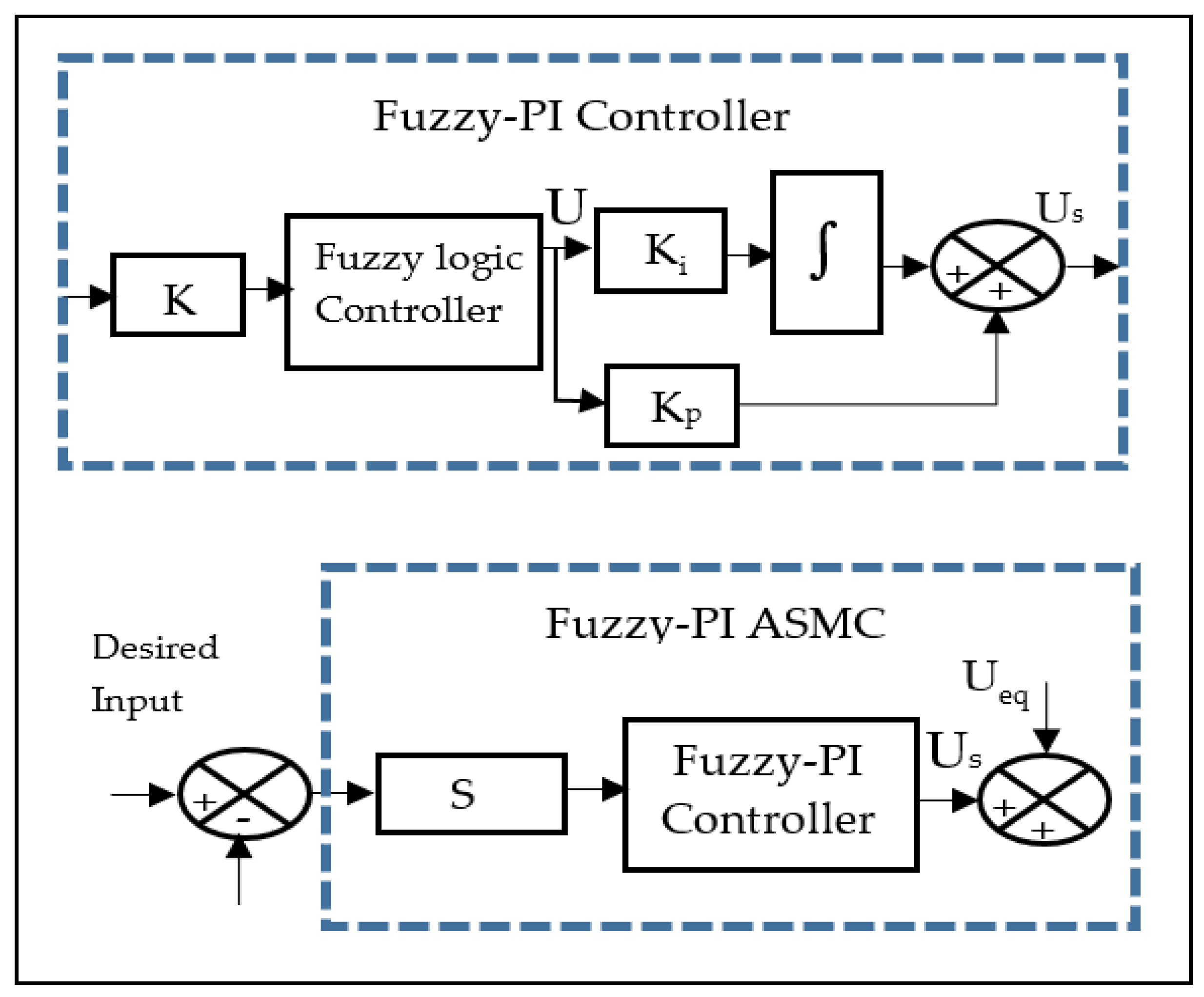
Figure 2.
Fuzzy logic membership functions for input and output.

Figure 3.
Results obtained via Fuzzy-PI ASMC and ASMC for ball position.

Figure 4.
Results obtained via Fuzzy-PI ASMC and ASMC for ball velocity.
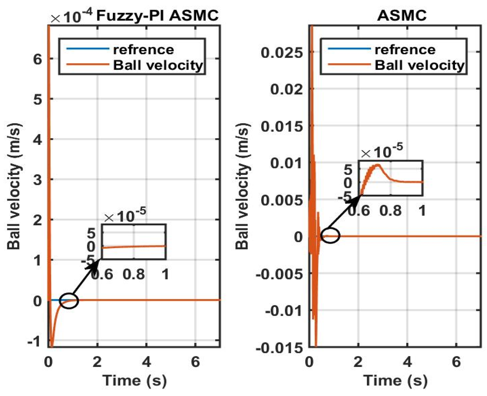
Figure 5.
Results obtained via Fuzzy-PI ASMC and ASMC for current coil.

Figure 6.
Control signal obtained via Fuzzy-PI ASMC and ASMC for control signal.

Figure 7.
Parameter estimations obtained via Fuzzy-PI ASMC and ASMC for .

Figure 8.
Parameter estimations obtained via Fuzzy-PI ASMC and ASMC for .

Figure 9.
Parameter estimations obtained via Fuzzy-PI ASMC and ASMC for .

Publisher’s Note: MDPI stays neutral with regard to jurisdictional claims in published maps and institutional affiliations. |
© 2022 by the authors. Licensee MDPI, Basel, Switzerland. This article is an open access article distributed under the terms and conditions of the Creative Commons Attribution (CC BY) license (https://creativecommons.org/licenses/by/4.0/).
Share and Cite
MDPI and ACS Style
Mourad, A.; Youcef, Z. Adaptive Sliding Mode Control Improved by Fuzzy-PI Controller: Applied to Magnetic Levitation System. Eng. Proc. 2022, 14, 14. https://doi.org/10.3390/engproc2022014014
AMA Style
Mourad A, Youcef Z. Adaptive Sliding Mode Control Improved by Fuzzy-PI Controller: Applied to Magnetic Levitation System. Engineering Proceedings. 2022; 14(1):14. https://doi.org/10.3390/engproc2022014014
Chicago/Turabian StyleMourad, Achouri, and Zennir Youcef. 2022. "Adaptive Sliding Mode Control Improved by Fuzzy-PI Controller: Applied to Magnetic Levitation System" Engineering Proceedings 14, no. 1: 14. https://doi.org/10.3390/engproc2022014014