1. Introduction
Accurate and reliable vehicle positioning is a cornerstone of autonomous driving and advanced driver-assistance systems (ADASs). Traditional positioning systems, such as GPS and inertial measurement units (IMUs), often face limitations in environments with poor signal reception or dynamic conditions, particularly when driving in urban areas surrounded by tall buildings. In recent years, image-based positioning methods have emerged as a promising complement to conventional sensors, offering enhanced localization capabilities through visual information. However, the performance of vision-based systems is highly dependent on ambient lighting, which can vary significantly under different driving conditions. Addressing this challenge, this study proposes an image-based positioning system that fuses GPS, IMU, and camera inputs to improve localization accuracy [
1,
2,
3].
2. System Architecture
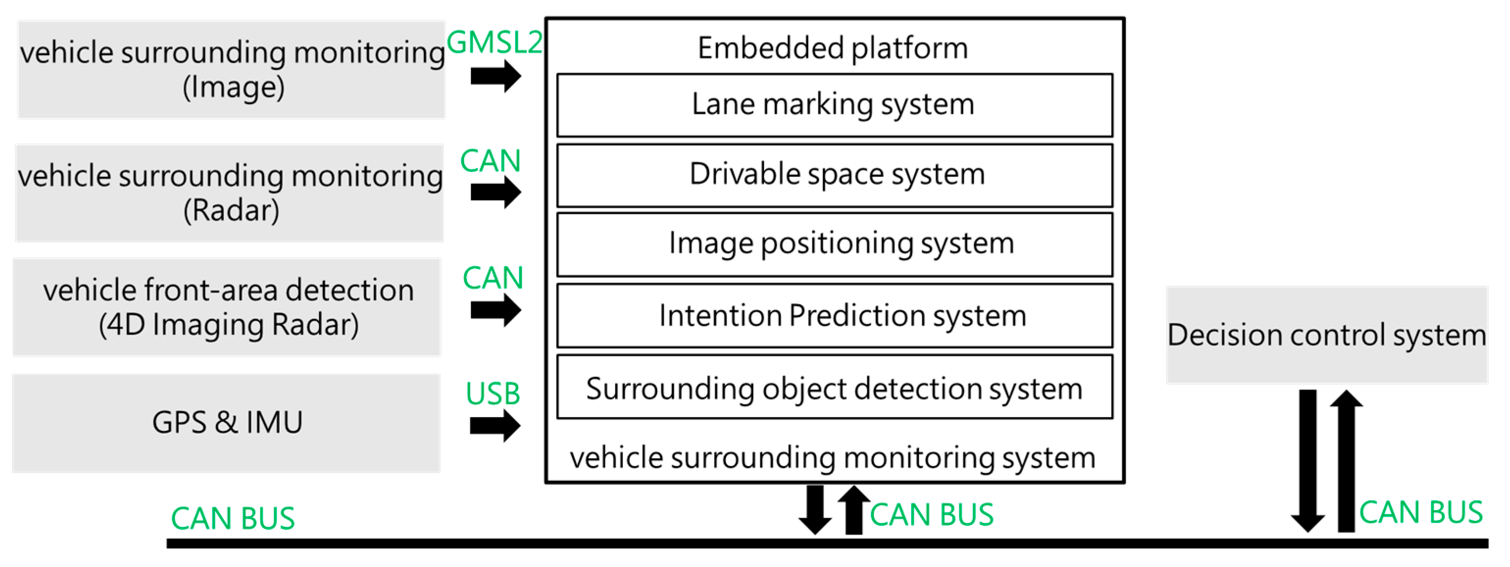
The vehicle surrounding monitoring system is designed to provide real-time environmental awareness by integrating multiple sensor modalities, including cameras, radar, GPS, and IMU. The system architecture comprises three primary modules: perception, sensor fusion, and decision-making (
Figure 1).
In the perception module, a set of cameras is mounted around the vehicle to capture a 360-degree field of view. These visual inputs are processed using deep learning-based object detection and semantic segmentation algorithms to identify surrounding vehicles, pedestrians, lane markings, and obstacles. In addition to visual sensors, radar systems provide complementary distance and velocity information, particularly under poor lighting or adverse weather conditions.
The sensor fusion module combines data from the cameras, GPS, and IMU to generate a unified and consistent representation of the vehicle’s environment. Through techniques such as Kalman filtering and probabilistic mapping, the system reduces uncertainty and improves the stability of object localization and vehicle positioning. The decision-making module utilizes the fused environmental model to support various driving functions, such as lane keeping, collision avoidance, and path planning. The surrounding monitoring system operates continuously to ensure the vehicle maintains situational awareness and can respond dynamically to changes in its surroundings, making it a critical component for autonomous driving and ADAS.
2.1. Image Positioning System
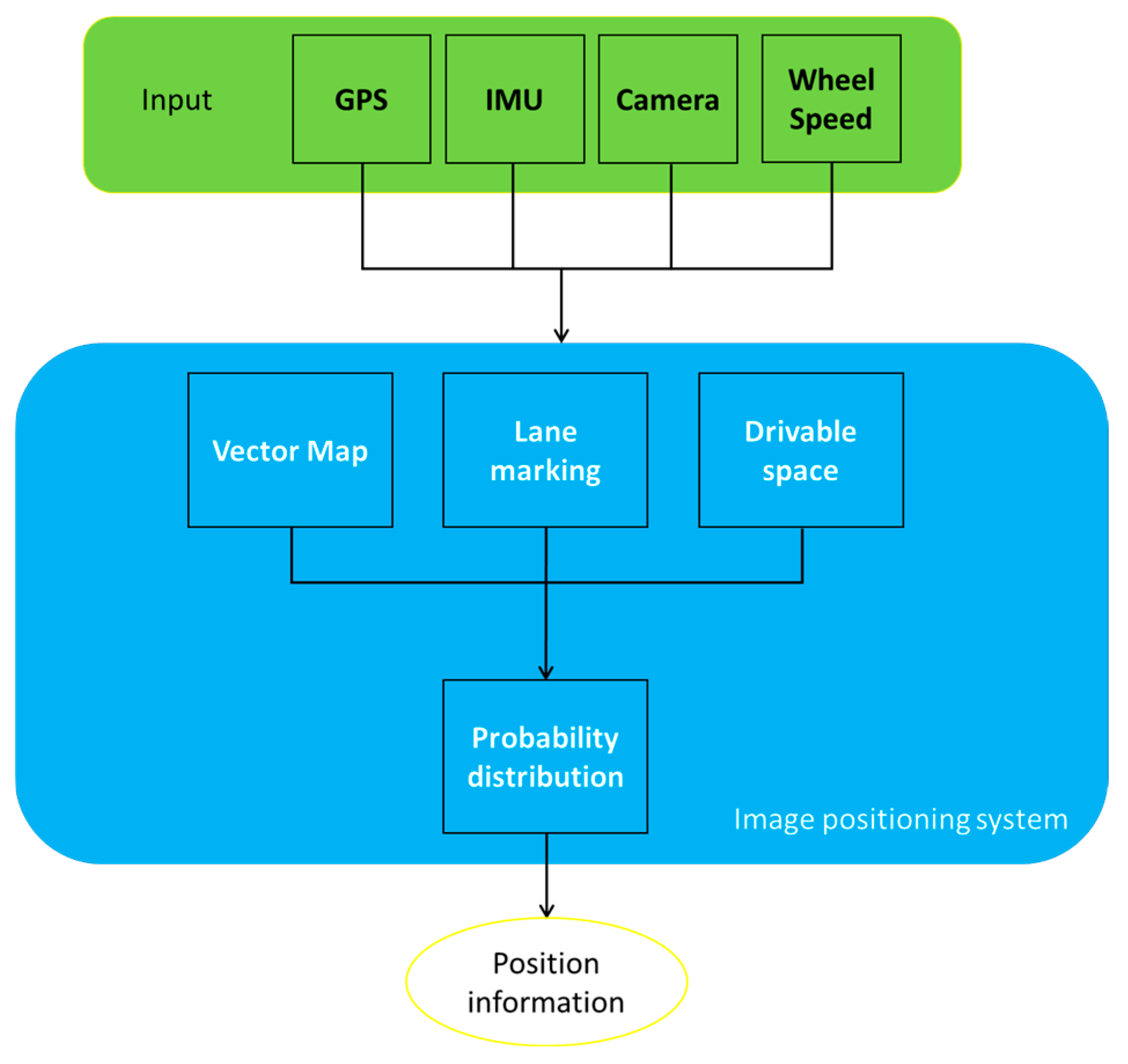
Image-based positioning systems have emerged as a powerful alternative or complement to traditional localization methods, such as GPS and IMU, especially in environments where satellite signals are unreliable or unavailable—such as urban canyons, tunnels, and indoor spaces. As shown in
Figure 2, these systems utilize visual information captured from onboard cameras to estimate the position and orientation of a vehicle or device within a known or partially known environment.
The core principle behind image positioning lies in extracting meaningful features from images—such as keypoints, edges, or semantic landmarks—and matching them against a pre-constructed visual map or database. Techniques such as visual odometry (VO), visual simultaneous localization and mapping (V-SLAM), and image retrieval-based localization are commonly employed to estimate relative or absolute positions [
4,
5,
6]. While GPS suffers from multipath effects and signal obstruction, image-based systems can offer higher spatial resolution and context awareness by leveraging the visual characteristics of the environment. When integrated with IMU and GPS in a sensor fusion framework, the system can achieve higher robustness and accuracy, particularly under challenging conditions such as low-light, heavy traffic, or high-rise urban settings.
Recent advances in deep learning and computer vision have further improved the performance of image-based localization, enabling the system to function effectively in dynamic and visually complex environments. Moreover, by adapting to varying lighting conditions, such systems can be applied to both day and night scenarios, making them highly suitable for autonomous driving, ADAS, and mobile robotics.
2.2. Vehicle Configuration
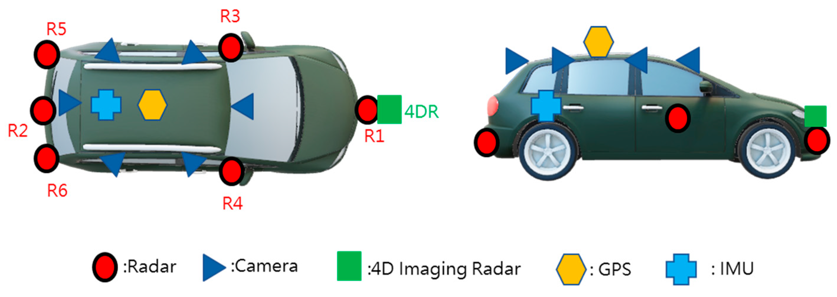
The test vehicle was outfitted with a comprehensive multi-sensor suite designed to provide full-surround environmental perception and accurate localization. The system includes six cameras, six radars, one front-facing 4D imaging radar, a GPS receiver, and an IMU (
Figure 3). This configuration enables robust sensing across varying environmental and lighting conditions, supporting both image-based positioning and sensor fusion tasks.
2.3. Vehicular Dynamics
Based on the tire model and control strategies [
7,
8], the estimated yaw rate is computed using the car’s geometry, actual longitudinal speed, steering angle, and the understeer coefficient, which can be adjusted to achieve the desired vehicle behavior. Positive values indicate under-steer characteristics, while negative values correspond to over-steer behavior.
Here, represents the road wheel angle, which is directly proportional to the steering wheel angle, V denotes the vehicle velocity, L is the wheel base length and the understeer coefficient, is the desired understeer coefficient, g refers to the acceleration due to gravity, and VSR stands for the vehicle steering ratio.
3. Results
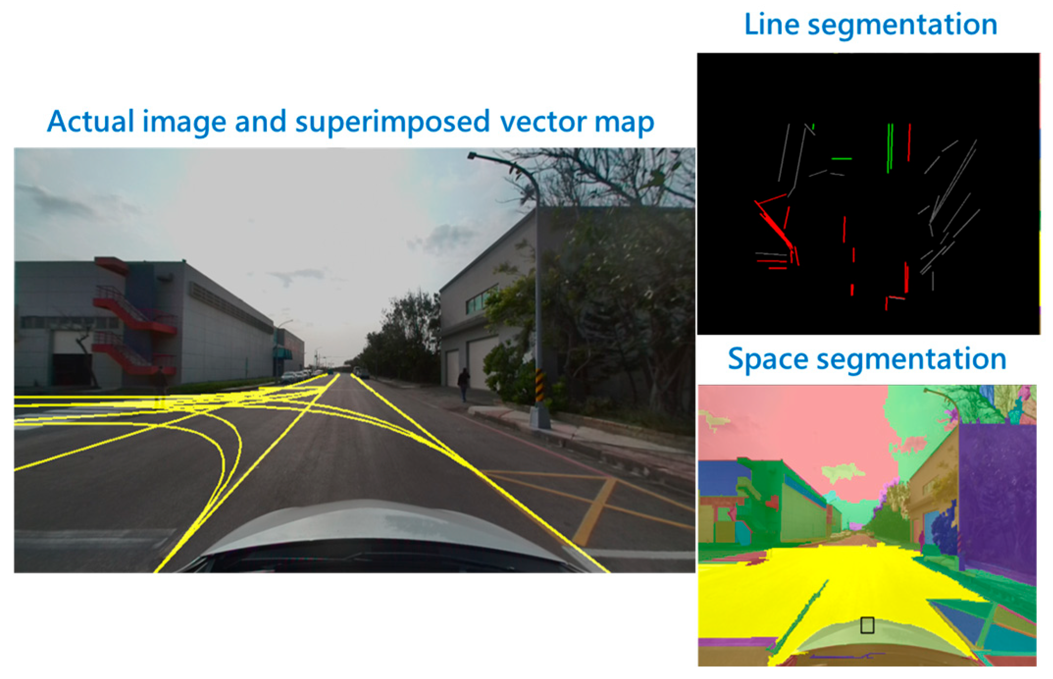
In autonomous systems, particularly in the context of image localization and perception, different approaches are utilized to process and interpret the data collected from the environment. Three key concepts in this domain are space segmentation, line segment segmentation, and probability distributions. These methodologies are crucial for understanding and making decisions based on the surrounding environment, as shown in
Figure 4. In space segmentation, the yellow region represents the drivable area.
3.1. Daytime Image-Based Positioning Test Result
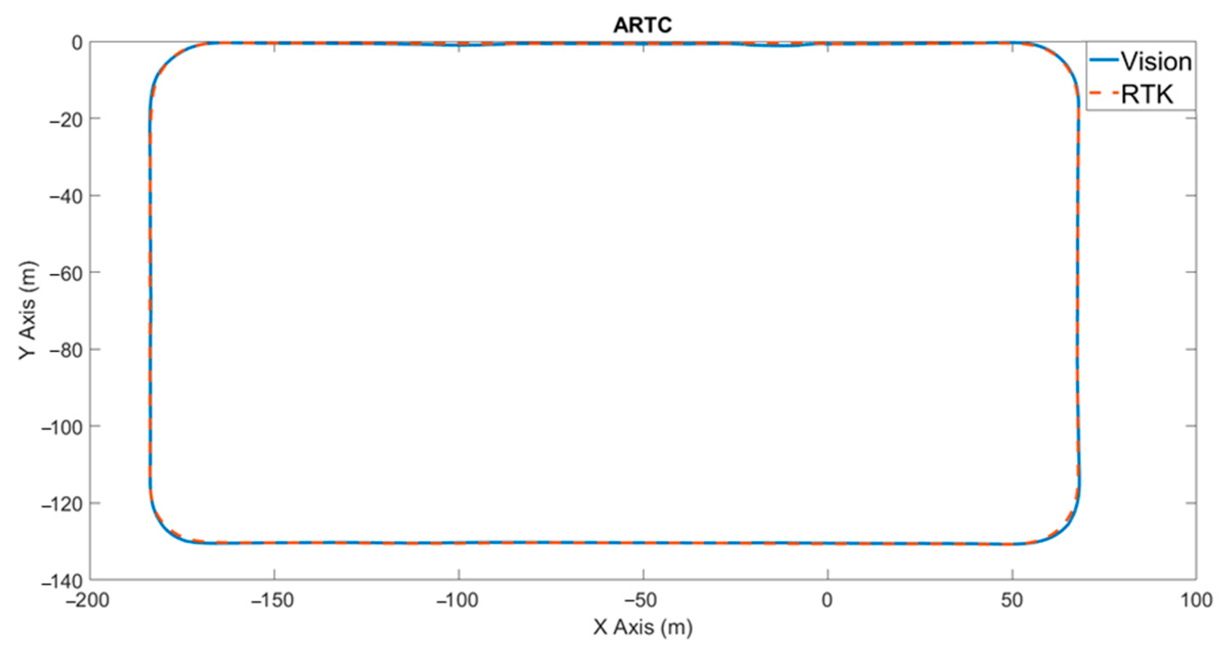
To evaluate the baseline performance of the proposed image-based positioning system, a series of tests was conducted under daytime conditions. During these experiments, the vehicle operated in open-sky environments with sufficient natural lighting, allowing the camera to capture high-contrast and texture-rich images of the surrounding environment. Under stable lighting and clear visibility, the image-based system demonstrated strong localization accuracy. In most scenarios, the system was able to maintain a mean positioning error of less than 0.6 m, which is comparable to standard GNSS-based solutions in open areas. Furthermore, the integration of IMU data through sensor fusion significantly enhanced temporal consistency, reducing the effects of image blur or momentary occlusions caused by dynamic objects such as other vehicles or pedestrians, as shown in
Figure 5. These results confirm that the image-based positioning system is effective during daytime operations, offering high spatial resolution and robustness in GPS-available conditions, while also acting as a fallback or enhancement mechanism in GPS-degraded scenarios such as urban canyons.
3.2. Nighttime Image-Based Positioning Test Result
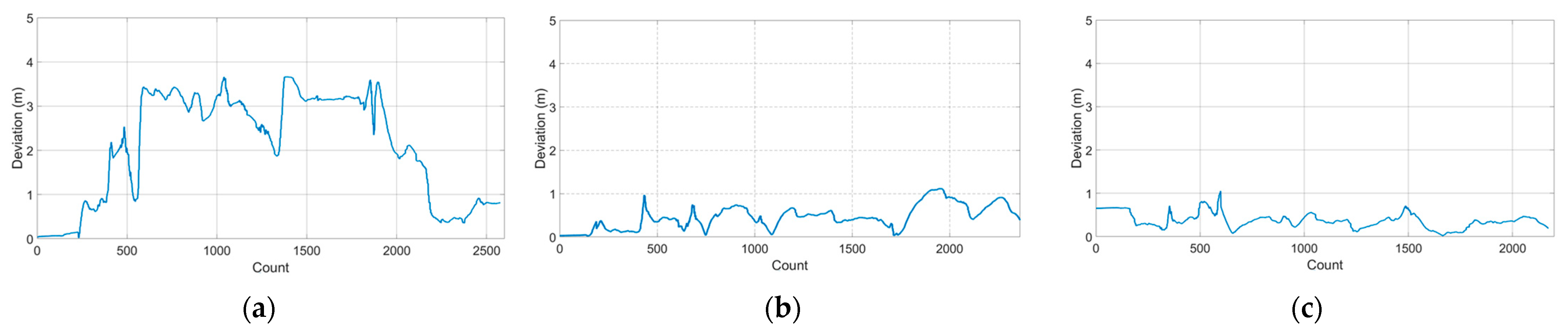
In contrast to daytime conditions, nighttime image-based positioning presents unique challenges due to reduced ambient illumination, glare from artificial light sources, and a lower signal-to-noise ratio in camera sensors. To assess the system’s adaptability in such conditions, experiments were conducted under three controlled lighting scenarios: daylight lamp, low beam, and high beam, each simulating different headlight settings typically encountered during night driving.
The results revealed that both the low-beam and high-beam conditions significantly improved image clarity, allowing for more reliable feature extraction and matching. Under these conditions, the system achieved a positioning accuracy improvement of up to 82% compared to low-beam scenarios. In particular, high-beam lighting enhanced the visibility of distant road features, enabling better forward localization even in semi-structured or poorly marked roads.
In contrast, under low-beam conditions, the system experienced a moderate decrease in performance, primarily due to a limited field of view and reduced contrast in distant objects. Nevertheless, by leveraging temporal data from the IMU and applying light adaptation techniques in image preprocessing, the system was still able to maintain operational accuracy. The correction percentage observed between low-beam and high-beam conditions was approximately 19.6%, indicating that lighting intensity directly impacts the system’s localization fidelity, as shown in
Figure 6 and
Table 1.
4. Conclusions
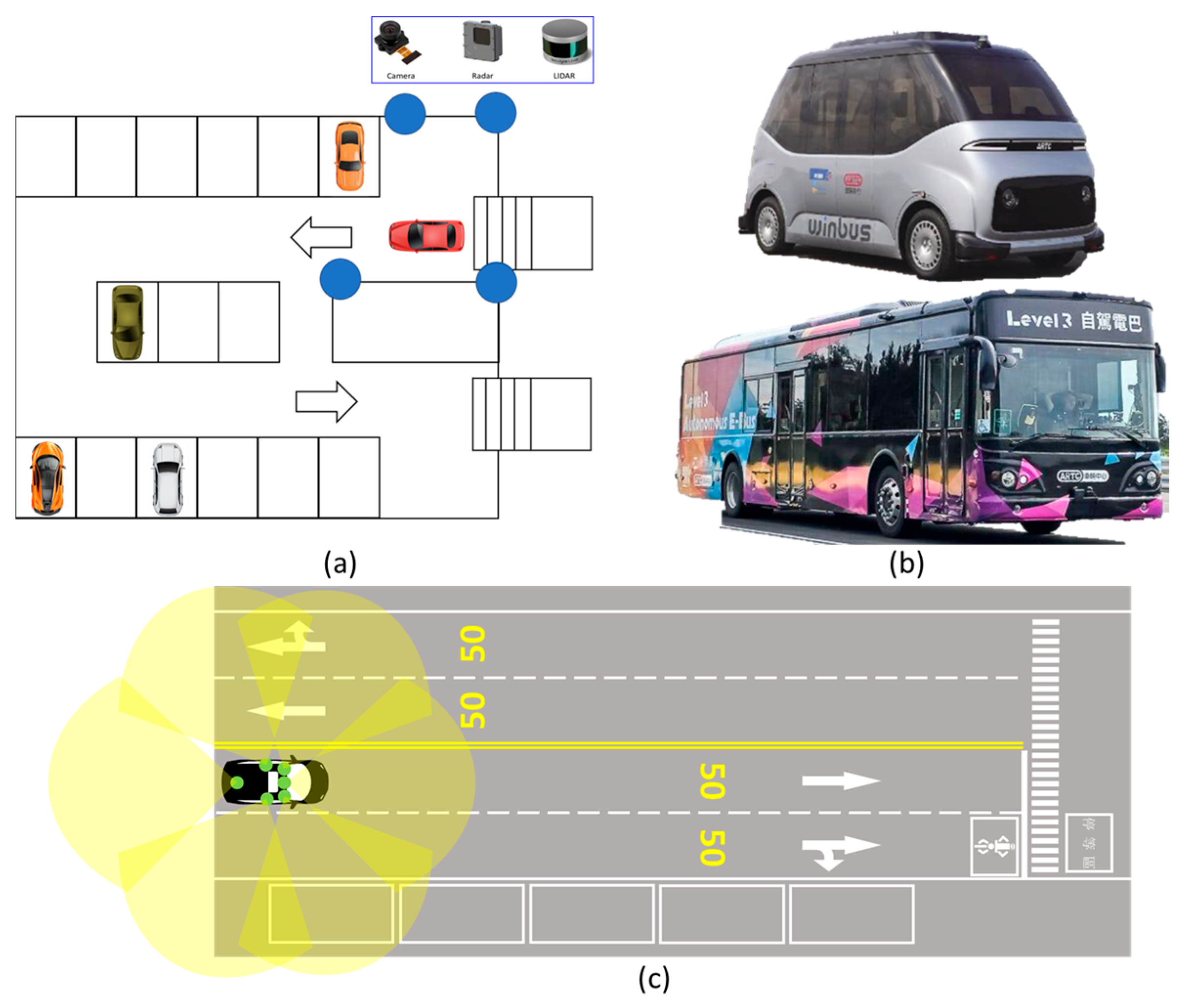
We explored the capabilities and practical applications of visual localization in intelligent transportation systems, with an emphasis on diverse scenarios such as autonomous parking, highway driving, and dedicated bus lanes, as shown in
Figure 7. With increasingly accurate and cost-effective sensors, visual localization is becoming more robust and feasible. In autonomous parking, it enables precise alignment and self-parking; in highway environments, it supports lane keeping and navigation; and in dedicated bus lanes, it enhances path adherence and operational safety.
Second, experimental results demonstrate the robustness of the image-based positioning system under night-time driving conditions, highlighting its reliability even in low-light environments. Furthermore, the system shows strong potential for integration with adaptive driving beam systems, enabling dynamic optimization of visibility and localization performance based on real-time lighting conditions. Overall, visual localization not only proves adaptable across various transportation scenarios but also maintains stable performance under challenging conditions, positioning it as a critical enabler for the future of smart mobility and autonomous driving technologies.
Author Contributions
Conceptualization, Y.-S.L., S.-H.L. and Y.-R.C.; methodology, Y.-S.L. and Y.-R.C.; software, S.-H.L. and Y.-S.L.; validation, Y.-S.L. and S.-H.L.; formal analysis, Y.-S.L.; investigation, Y.-R.C. and H.-T.M.; resources, Y.-S.L.; data curation, S.-H.L.; writing—original draft preparation, Y.-S.L., Y.-R.C. and S.-H.L.; writing—review and editing, Y.-S.L.; visualization, S.-H.L.; supervision, Y.-S.L.; project administration, Y.-S.L.; funding acquisition, Y.-S.L. All authors have read and agreed to the published version of the manuscript.
Funding
This research was supported by the Department of Industrial Technology of MOEA (the Ministry of Economic Affairs), Taiwan, R. O. C., under Contract No. 114-EC-17-A-25-1588.
Institutional Review Board Statement
Not applicable.
Informed Consent Statement
Not applicable.
Data Availability Statement
Datasets were obtained from selected sites by the researchers. These may be requested by sending an e-mail to the corresponding author.
Conflicts of Interest
The authors declare no conflicts of interest.
References
- Chiang, K.-W.; Lin, C.-X.; Tsai, S.; Huang, C.-H.; Tsai, M.-L. Seamless realtime lane level vehicular navigation in gnss challenging environments using a rtk gnss/imu/vins integration scheme. Int. Arch. Photogramm. Remote Sens. Spat. Inf. Sci. 2023, XLVIII-1/W1-2023, 609–616. [Google Scholar] [CrossRef]
- Yang, X.; Xu, L.; Wang, L.; Tan, Y.; Zhou, J.; Wei, X.; Lu, Y. Real-Time Lane-Level Localization with GNSS and Vision Integration for Autonomous Vehicles. Sensors 2020, 20, 2166. [Google Scholar]
- Lin, Y.-S.; Lin, S.-H.; Jhang, T.-K. Research on cooperative vehicle positioning system and fault detection method. In Proceedings of the 2023 IEEE 5th Eurasia Conference on IoT, Communication and Engineering (ECICE), Yunlin, Taiwan, 27–29 October 2023; pp. 248–253. [Google Scholar]
- Kleineberg, A.; Ziegler, J.; Sattler, T. Visual Odometry and Mapping for Autonomous Driving: A Review. J. Field Robot. 2017, 34, 591–613. [Google Scholar]
- Engel, J.; Koltun, V.; Cremers, D. Direct Sparse Odometry. IEEE Trans. Pattern Anal. Mach. Intell. 2017, 40, 611–625. [Google Scholar] [CrossRef] [PubMed]
- Rodríguez-Martínez, E.A.; Flores-Fuentes, W.; Achakir, F.; Sergiyenko, O.; Murrieta-Rico, F.N. Vision-Based Navigation and Perception for Autonomous Robots: Sensors, SLAM, Control Strategies, and Cross-Domain Applications—A Review. Eng 2025, 6, 153. [Google Scholar] [CrossRef]
- Vasiljevic, G.; Bogdan, S. Model predictive control-based torque vectoring algorithm for electric car with independent drives. In Proceedings of the 24th Mediterranean Conference on Control and Automation (MED), Athens, Greece, 21–24 June 2016; pp. 316–321. [Google Scholar]
- Pacejka, H.B. Tyre and Vehicle Dynamics, 2nd ed.; Butterworth-Heinemann: Oxford, UK, 2006. [Google Scholar]
| Disclaimer/Publisher’s Note: The statements, opinions and data contained in all publications are solely those of the individual author(s) and contributor(s) and not of MDPI and/or the editor(s). MDPI and/or the editor(s) disclaim responsibility for any injury to people or property resulting from any ideas, methods, instructions or products referred to in the content. |