Proceeding Paper

Design, Fabrication and Launching of CanSat-Deploying High-Power Rockets †
by
Eleftherios Karampasis
1,
Vasilis Kiosoglou
1,
Styliani Chatzipetrou
1,
Christina Konstantinidou
1,
Konstantinos Marsouvanidis
1,
Emmanouil Minoudis
1,
Antonios Mouratidis
2 and
Pericles Panagiotou
3,4,*
1
Aristotle Space and Aeronautics Team (ASAT), Aristotle University of Thessaloniki, 54124 Thessaloniki, Greece
2
ESERO Greece, Center for Interdisciplinary Research and Innovation, Aristotle University of Thessaloniki, 57001 Thessaloniki, Greece
3
Laboratory of Fluid Mechanics and Turbomachinery (LFMT), Department of Mechanical Engineering, Aristotle University of Thessaloniki, 54124 Thessaloniki, Greece
4
UAV-iRC, Center for Interdisciplinary Research and Innovation, Aristotle University of Thessaloniki, 57001 Thessaloniki, Greece
*
Author to whom correspondence should be addressed.
Presented at the 15th EASN International Conference, Madrid, Spain, 14–17 October 2025.
Eng. Proc. 2026, 133(1), 84; https://doi.org/10.3390/engproc2026133084
Published: 30 April 2026

Abstract

This work presents a service-oriented launcher for ESERO Greece’s CanSat 2025, delivering four reusable rockets that reach 1000 m and perform clean, near-apogee payload deployment with safe recovery. A requirements-driven process combined with systems engineering principals that utilized simulation based conceptual design, trajectory analyses and subsystem ground testing managing to deliver a modular, cost-effective and reusable system. All vehicles were used offering 12 flawless flights, fulfilling their missions. Overall, results validate the architecture and methodology under competition constraints, with vehicles ready for reuse and clear avenues for simplification offering directions for further future improvements.

1. Introduction

The rapid expansion of the satellite sector within the last 10 years has transformed many aspects of daily life, while also providing opportunities for students in their first steps in the field. More specifically, the ESA CanSat initiative provides a unified framework in which student teams design, build, and fly payloads with specific and uniform dimensions and constraints, allowing comparable engineering experiences and outcome assessment across countries. In Greece since 2015 the national CanSat competition has been established as an annual event, integrating education and aerospace technologies into a single event.
For the 2025 competition, ESERO Greece tasked the Aristotle Space and Aeronautics Team (ASAT) with providing a reliable launch service using four reusable deployer rockets capable of reaching an apogee of 1000 m and reliably releasing CanSats at their operating altitude, followed by safe recovery of both the vehicle and payloads. Envisioned as a service rather than a one-off prototype, the project includes multiple flights within the event window, reusability with rapid turnaround, and consistent data delivery.
The engineering challenge centers on three coupled objectives, reaching an apogee with a given accuracy, payload separation near apogee, i.e., the CanSat must leave the rocket and deploy safely mid-air to continue its mission while both bodies (rocket and CanSat) descend individually to the ground. Lastly, low-drift recovery must be ensured to comply with the safety requirements of the launch site and ease the work of the ground recovery teams.
To that end, the rocket is developed using a requirements-driven as well as systems engineering methodology starting with system definition (propulsion, structural, avionics, payload, recovery), tradeoff studies (motor class, stability margin, vehicle mass, descent rates) and verification by simulations and component testing. The resulting architecture is modular, enabling quick inspection, assembly, and disassembly and parachute repackaging between flights.
The objectives of this paper are summarized as follows:
  • to provide an architecture for CanSat-deploying rockets operating at 1km, validated in-flight
  • to document the above along with the project’s workflow spanning from simulation to ground and flight testing, and
  • to underline some key lessons learned that can lower the risks and costs for future events.

2. Methodology

The methodology follows a requirements-driven process adapted to a tight schedule with no pre-event flight testing. The work progressed from analytical estimation and preliminary simulation, through design maturation and component level definition, to system integration and final flight.
The process starts with initial performance estimation to select the motor class, mass targets, and recovery constraints. A preliminary vehicle model in OpenRocket [1] (open-source, and fully featured model rocket simulator used to design, simulate, and analyze flight performance) provides ascent kinematics, apogee sensitivity to mass variation, wind loads and launch rail dimensions impact. Concerning the wind loads, the OpenRocket model is used, which is based on user input for the wind’s magnitude, direction and deviation from the average values provided. In parallel, a preliminary CAD of the various components is made to establish basic values for propulsion, avionics, payload deployment and recovery subsystems. The CAD model serves as the basis for a mass properties estimate (component-level breakdown and CG), which is continuously reconciled against the OpenRocket model to keep the simulation aligned between them.
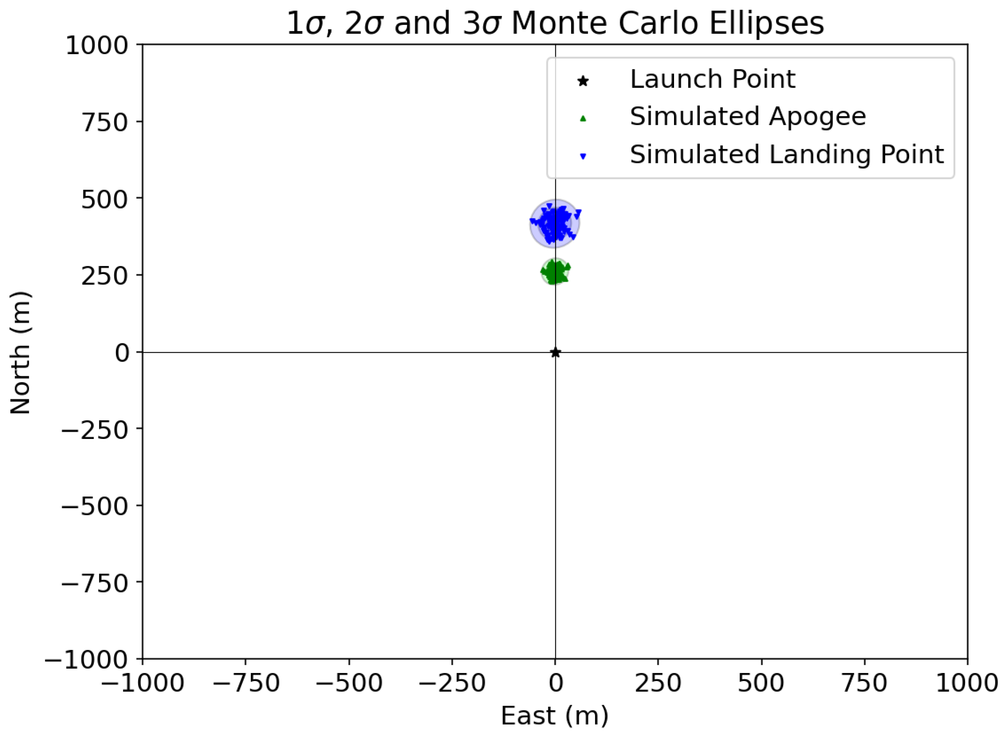
Aerodynamic characteristics [2] for nosecone [3] and fin [4] assemblies, as well as the parachute C D are derived from literature sources and standard empirical equations. The resulting ascent and descent models are used to size the recovery system and to set dimensions that limit peak opening loads [5] and drift. A trajectory and dispersion analysis is also made using RocketPy [6] (open-source Python library for simulating high-power and sounding rocket trajectories, offering a realistic 6-DOF), utilizing Monte Carlo simulations over measured and forecast wind profiles to identify the recovery radius and the maximum operating wind value for a safe launch as shown in the Figure 1 and Table 1 below. This analysis also results in launch rail orientation and safety ranges for spectators and ground operations. After consulting the authorities for the weather conditions usually encountered at the testing range, a parametric analysis is conducted, with the wind velocity ranging from North to South at 1, 2, 3 to 6 Beaufort (Bft), as well as from West to East, East to West, etc for the same wind values. The worst case scenario is determined to be winds blowing from South to North because the rail has an inclination to the vertical plane of about 5 degrees to give a heading far from unwanted landing areas and so a small percent of the total trajectory is made towards the N and so S to N winds pose the greatest margin for deviation.
Verification emphasized ground testing in the absence of a pre-event flight. Avionics are tested for sensor calibration, logging integrity, arming, and pyro-channel continuity. The payload deployment mechanism is rigorously tested for successful and repeatable operation, followed by ground ejection tests to verify charge sizing. The recovery system is validated via canopy inspections, line-strength checks, packing procedure rehearsals, and drop tests to measure descent-rate consistency. System-level assembly, mock up tests and checklists are made to reduce turnaround time and to de-risk handling during event.

3. Mission Requirements

The mission requirements for the project are derived from the specifications of the CanSats and their constraints, as indicated by the ESA’s technical specifications and are visible in the Table 2 below. The modular approach of the design and the existence of sufficient spare parts enable the disassembly and reassembly of the vehicle in under 2 h in order for up to 12 launches to occur within the 2-day launch event.
Regarding the recovery requirements, the airspeed at drogue deployment [7] is limited to 20 m/s to minimize the drag-induced forces and to protect the CanSats by reducing the chance of re-contact. The main parachute is deployed at 300 m above the ground, and it is designed to land the rocket with a terminal velocity of 5–6 m/s for as smooth a landing as possible in order to minimize damage and enable quick refurbishment and rapid turnaround time. Regarding safety during launches, the authorities imposed a limit on wind velocity of 4 Bft with a safety factor of 2 and established a subsequent recovery range of 1 km ensuring rapid turnaround and spectator safety based on the findings of the trajectory study.

4. Vehicle Architecture

As previously stated, the vehicle architecture is coupled with its modular design and is organized as described below:
  • Propulsion Subsystem uses a commercial J-class solid rocket motor sized with OpenRocket to reach the target apogee while preserving adequate static stability [8] across the boost phase. The nominal motor specification is 1265 N·s total impulse with a 1.67 s burn, providing margin for winds and minor mass variation. For these values, given the lack of data from the supplier, no dispersion is considered for total impulse and burn time in the MC trajectory analyses conducted.
  • Avionics Subsystem comprises of a 3D printed stack built for two COTS flight computers with barometric sensing augmented by IMU and GNSS, providing redundant pyro channels for separation and recovery events and a telemetry link for recovery. For the deployment of the main-canopy, two servos actuate a 3-ring mechanism, one servo per flight computer for functional redundancy. SRAD PCBs implement the ignition process, utilizing LoRa from ground antennas for long-range (400 m), low-power links. An onboard camera also records ascent and descent for event documentation.
  • Payload Subsystem houses the CanSat with defined clearances and a low-shock ejection path. Near apogee the flight computers fire two cross-linked e-matches that ignite 0.2 g of black powder to drive a spring-loaded pusher. The pusher’s pin punctures a pair of 25 g CO 2 cartridge layout producing ≈60 N of ejection force. This force is originated from each cartridge, for redundancy, while the 30 N of force is necessary in order to push both the CanSat as well as the main and drogue parachutes out of the payload tube. The parachutes function as a piston though as there are not rigid bodies and their surfaces are not smooth, substantial portion of that force is used to overcome these characteristics. The compression-fit nosecone shoulder separates under the overpressure, releasing the CanSat first, then the drogue and main parachutes.
  • Aerostructural Subsystem comprises of the airframe divided into four zones with material choices tailored for each function. From top-down, a carbon-fiber [9,10] nosecone mates to an aluminum-6061 shoulder a carbon-fiber payload tube houses parachutes, CanSat, and the ejection mechanism a fiberglass avionics tube enables RF communication for telemetry and GNSS and a carbon-fiber motor tube integrates the motor and fin assembly. Aluminum bulkheads couple tubes, support the ejection hardware and servo assembly, and transfer thrust from the motor through the upper structure a lower motor bulkhead retains the motor pre-ignition.
  • Recovery Subsystem [11] utilizes a dual deployment [12]. A drogue at apogee stabilizes the vehicle and sets a ≈15 m/s descent, while the main canopy deploys at ≈300 m AGL, and is actuated by the 3-ring system via two 15 kg servos, to achieve ≈6 m/s terminal speed. The recovery layout and harness paths are arranged to minimize drift and keep landings within the designated area for winds up to 4 Beaufort.
  • Ground Segment comprises a 12 m triangular-truss launch rail in three segments with an aluminum guide profile and two launch lugs, the structure mounts to a three-legged base and is fixated by three steel cables. A pad controller provides continuity checks, and a compact ground station handles telemetry and data offload.

5. Vehicle Design & Analysis

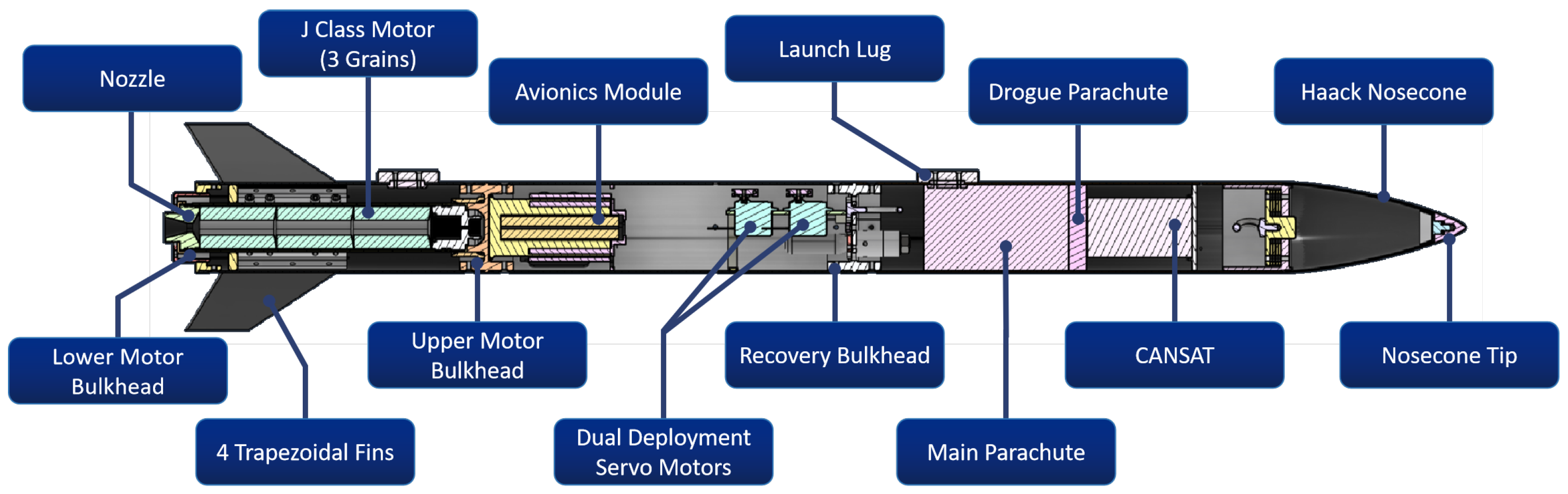
Geometry and sizing decisions are driven by both simulation, literature [13,14] and past experiences and the final outcome can be seen in Figure 2 and the vehicle characteristics in Table 3. Nosecone selected for subsonic performance using initially OpenRocket stability predictions and drag comparisons across canonical profiles led to adoption of a Haack-series [3] shape for favorable C D [15]. Fin geometry follows bibliography [16] on model rockets and OpenRocket, converging on four trapezoidal fins with rounded-edge parallelogram sections to balance stability, drag, and manufacturability while a three-fin option is rejected due to reduced stability margin. The airframe diameter is minimized within manufacturing and packaging constraints to reduce drag, and tube lengths are set by component accommodation and stability requirements. Lastly ventilation holes in payload and avionics bays equalize pressure and improve barometric altitude measurement fidelity.
The recovery system is sized using literature correlations [17,18] and simulations. Toroidal canopies are selected for their higher C D [15] relative to alternative platforms. Steady-descent calculations yield a 1.6 m main canopy and 0.6 m drogue, meeting the 6 m/s landing target while controlling opening loads [19]. Peak inflation forces and line tensions are estimated to dimension ropes and shock cords with appropriate factors of safety while OpenRocket ascent predictions and RocketPy dispersion with Monte-Carlo winds are used to update the deployment altitudes.
Ejection mechanisms are engineered for adequate retention during boost and release near apogee. The SRAD CO 2 system [20] uses a 0.2 g black-powder (BP) charge in a cup to drive a spring-loaded pin that punctures a 25 g cartridge (dual-cartridge redundancy), providing the force needed to expel the payload and clear the nosecone shoulder. The secondary deployment of the main is accomplished by the SRAD 3-ring quick-release, adapted from skydiving equipment, when the vehicle descends through ≈300 m, the flying computer command two redundant servos to pull the release rod and free the interlinked rings, allowing the main canopy to extract cleanly. Together, these design choices align the physical system with the modeled trajectory profiles as well as the safety constraints without changing the requirements or operational concept established for the competition.

6. Component Manufacturing & Testing

Recovery tests conducted for the ejection mechanism with the objective during the SRAD ejection mechanism testing was to see the amount of BP needed for the cartridge puncture, the characteristics of the spring, and the quantity of the CO 2 needed for the ejection. It was tested with dead weights simulating the CanSat and, with over 20 tests and 18/20 successful tests in a row (90% success rate), the system functioned efficiently. During recovery tests the entire layout and payload simulator were successfully ejected out of the tube. Additianaly ground tests for the second deployment mechanism were performed on the 3-ring system, which all deemed successful.
Electronics testing conducted following the design and assembly of the custom PCBs, as well as a series of range tests to evaluate the wireless communication performance. The system maintained a stable connection over a distance of up to 3 km in line of sight conditions, confirming the reliability of the communication link under event conditions.
Total vehicle assembly tests were also made to ensure the proper integration of all components, while also revealing areas that required further work or modification—such as sanding the tubes for proper fitting with the bulkheads and adjusting the launch lug dimensions to ensure proper compatibility with the aluminum rail profile.
Composites manufacturing focusing on fins and nosecone were also materialized. The fins were fabricated using ‘sandwich’ method [21] with a carbon–fiberglass–carbon layup, designed to increase stiffness and suppress fin fluttering. Each laminate consisted of outer carbon fiber skins (±45° and unidirectional plies) and a central fiberglass core, consolidated with epoxy resin under vacuum for approximately 48 h. The parts were cut with water-jet tool for dimensional accuracy, and the leading and trailing edges were sanded for better aerodynamic efficiency. Regarding the nosecone, it was produced from 2 × 2 twill carbon fiber using eight plies arranged as patterns for full mold coverage of the developed cone geometry. After resin impregnation and vacuum curing for about two days, the surface was finished to achieve precise fitting with the aluminum shoulder.
3D-printed parts are also heavily utilized in vital section of the vehicle such as the avionics bay, servo housing, 3-ring pulleys, motor centering ring and parachute spacer. The intricate geometries and the balance of durability and weight made the 3D printing a necessity with the parts fabricated with PLA, or ASA.
Metal parts manufacturing from Aluminum 6061 were also utilized for components as all the bulkheads which distribute the motor loads, the set of launch lugs and the nosecone shoulder where mass ballast along with smooth surface was required. All components were sized internally and were machined using three-axis CNC mills.

7. Flight Performance & Data

During the 2-day event all 12 rockets (one test-flight and eleven cansat-deploying flights) completed successfully their mission deploying their payloads and being successfully recovered. Before every flight a trajectory simulation estimated the recovery site taking into consideration the variations in wind speed from 1–5 m/s on average. The wind speed values are taken from the local weather station in meters per second with one decimal accuracy and a 15-min interval. The recovery system faced some issues where the main and drogue tenders frequently entangled with each other resulting in the deployment of either of the chutes instead of the dual deployment. From flight 7 onward, the layout was deemed unreliable with only 3/7 successful dual deployments and thus the drogue was removed from the remaining flights. The flight data are shown in Table 4.
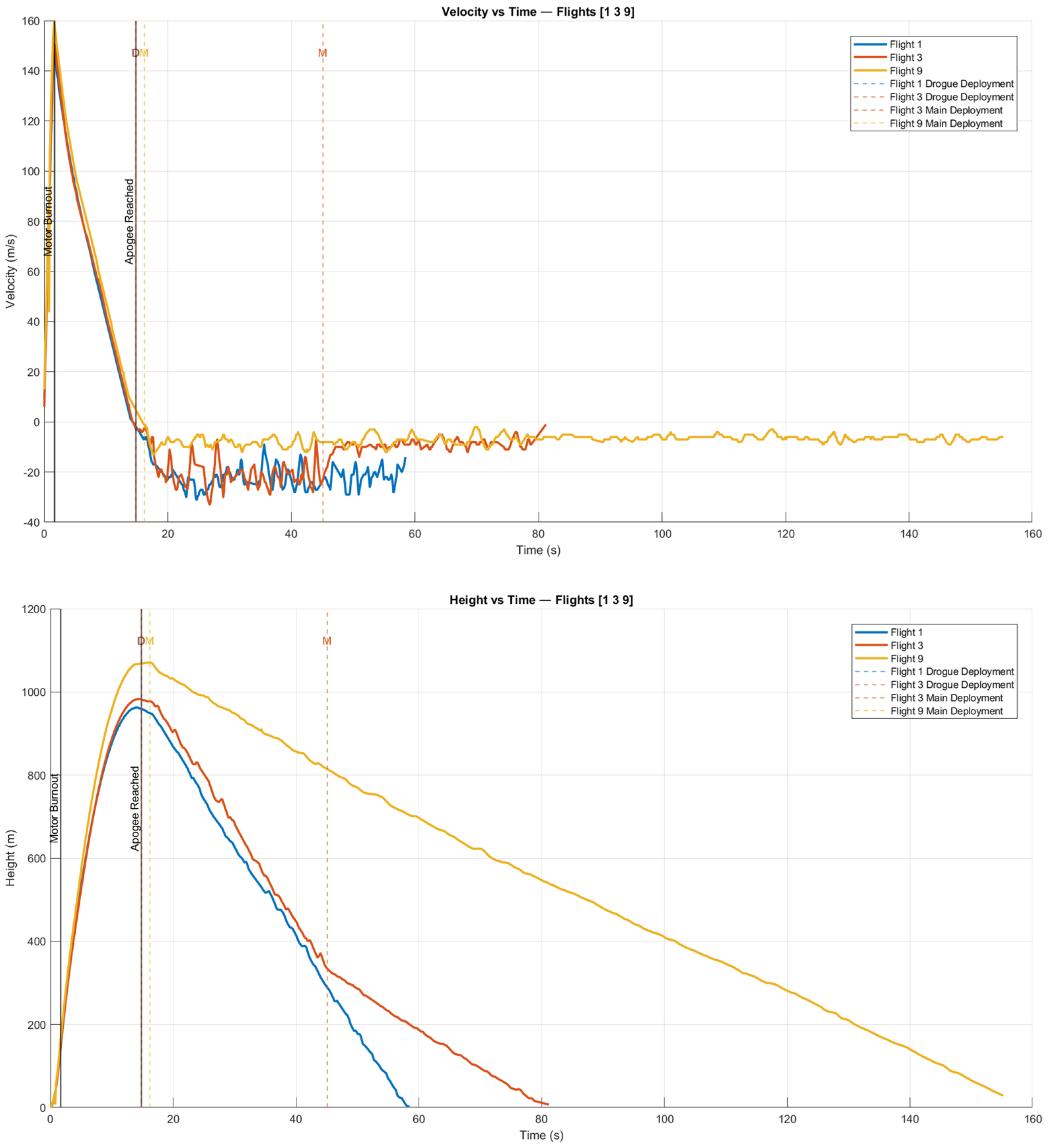
From the diagrams in Figure 3 it is obvious that the method of recovery affects the velocity and altitude profiles. Flights 2, 3 and 5 which had successful dual deployment tend to have longer flight durations and 2 distinct areas of different median descent velocities and also different gradients of altitude decrease. In the case of flights 1, 6 and 7 where only the drogue was deployed the flight time was noticeably smaller while in the remaining flights where only the main parachute was deployed the flight time was the longest by far while the descend velocity was also reduced. Regarding the maximum velocities and the apogees, for flights 1 through 7 the values diverge very little while from flight 8 till 12 the values increase marginally and the apogee exceeds 1070 m. This is expected as from the 8th flight the drogue was removed and thus the subsequent mass (300 g) cause an increase in both values.

8. Conclusions & Future Steps

Over two consecutive days the team conducted 12 successful launches and recoveries of which 11 student missions plus one test flight, thus meeting the service requirements and validating the architecture within competition conditions. The most critical element, the dual CO 2 ejection system, operated with 100% reliability, confirming its technical soundness. Flight data also indicated that, in very light winds (≤2 m/s, ≈2 Bft), a dual-deployment recovery sequence was more complex than necessary for recovery range control. Likewise, the use of two flight computers proved conservative given the short ranges involved (close ground station, apogee, and recovery area), yet it will be retained for reliability.
Finally, flight data confirmed the installed solid motor provided excess impulse a 200 g nose-cone ballast was therefore required to consistently achieve the 1 km apogee target. With the mission objectives achieved, the recovered vehicles are ready for reuse in CanSat 2026 in collaboration with ESERO Greece. The modular design fosters targeted optimizations, including a single-parachute recovery configuration tuned for a specific wind loads and descent rate to simplify operations in light winds, and possibly the replacement of the 400 g ballast with a second CanSat to double the payload capacity while preserving apogee budget. These changes, implemented within the existing interfaces, would increase utility without altering the proven core architecture.

Author Contributions

Conceptualization, E.K.; methodology, E.K., E.M. and P.P.; formal analysis, E.K. and P.P.; investigation, E.K., S.C., C.K., V.K. and K.M.; resources, E.K., E.M. and P.P.; writing—original draft preparation, E.K.; writing—review and editing, E.K. and P.P.; supervision, P.P.; project administration, E.K.; funding acquisition, A.M. and P.P. All authors have read and agreed to the published version of the manuscript.

Funding

This research was carried out with the support of the European Space Agency (ESA) in the context of the “Implementation of the European Space Education Resource Office (ESERO) Greece” Contract No.: 4000136545.

Data Availability Statement

The data presented in this study are available on request from the corresponding author due to privacy reasons.

Conflicts of Interest

The authors declare no conflicts of interest.

References

  1. Niskanen, S. Development of an Open Source Model Rocket Simulation Software. Bachelor’s Thesis, Helsinki University of Technology, Espoo, Finland, 2009. [Google Scholar]
  2. Stroick, G. Nose Cone and Fin Optimization; Tripoli Minesota: Harris, MN, USA, 2011. [Google Scholar]
  3. Carvalho, L.d.A.S.; Cavalcante Filho, G.C. Reference CFD Analysis of Drag Force for Different Nosecone Designs. In Proceedings of the IX Fórum de Pesquisa e Inovação do Centro de Lançamento da Barreira do Inferno, Parnamirim, Brazil, 24–26 November 2020. [Google Scholar]
  4. Nakka, R. Introduction to Rocket Design, Section 6: Fins. 2024. Available online: https://www.nakka-rocketry.net/RD_fin.htm (accessed on 3 November 2025).
  5. Alejos, J.M. Investigation of the Opening Shock Forces of a 24-Inch Diameter Drogue Parachute; California State University: Long Beach, CA, USA, 2022. [Google Scholar]
  6. Ceotto, G.; Schmitt, R.; Alves, G.; Pezente, L.; Carmo, B. RocketPy: Six Degree-of-Freedom Rocket Trajectory Simulator. J. Aerosp. Eng. 2021, 34. [Google Scholar] [CrossRef]
  7. Van Milligan, T. Selecting the Proper Size Drogue Parachute. Apogee Components Newsletter. 2014. Available online: https://www.apogeerockets.com/education/downloads/Newsletter361.pdf (accessed on 20 April 2026).
  8. Barrowman, J. Calculating the Center of Pressure of a Model Rocket; Technical Information Report No. 33; Engineering Company, Inc.: Phoenix, AZ, USA, 1988. [Google Scholar]
  9. Chawla, K.K. Composite Materials: Science and Engineering, 4th ed.; Springer: Berlin/Heidelberg, Germany, 2019. [Google Scholar]
  10. Park, S. Carbon Fibers; Springer: Berlin/Heidelberg, Germany, 2015. [Google Scholar]
  11. Knacke, T.W. Parachute Recovery Systems Design Manual; Para Publishing: Santa Barbara, CA, USA, 1991; pp. 5.1–5.111. [Google Scholar]
  12. Soriano Pascual, D. Recovery System Design for Lower Stages of Rockets. Bachelor’s Thesis, RWTH Aachen University, Aachen, Germany, 2017. [Google Scholar]
  13. Bunkley, J.; Caballes, M.J.L.; Ajuwon, M.; Guangming, C. Design Analysis of Rocket Tail Fins Aimed at Higher. In Proceedings of the 2022 Spring ASEE Middle Atlantic Section Conference, Newark, NJ, USA, 22–23 April 2022. [Google Scholar]
  14. Martin, D.J. NACA Technical Note 4197; National Advisory Committee for Aeronautics: Washington, DC, USA, 1958.
  15. Anderson, J.D. Fundamentals of Aerodynamics, 6th ed.; McGraw–Hill Education: New York, NY, USA, 2017. [Google Scholar]
  16. Ukirde, K.; Pawar, S.; Rahane, D.; Sagar, B.; Shinde, T. Aerodynamic Study of Various Fins for Missile Body. IJRASET J. 2023, 11, 1240–1252. [Google Scholar] [CrossRef]
  17. Evolution of Parachute Materials. Available online: https://chutes.nl/edl-tech/descent/materials.html (accessed on 30 October 2025).
  18. Cruz, J.R. Parachutes for Planetary Entry Systems; NASA Technical Report TM-2005-213622; National Aeronautics and Space Administration (NASA): Cleveland, OH, USA, 2005.
  19. Britting, T.; Leonardus, W.; Rudolf, J.; Toussaint, K.; Vukosavljević, M.S.; Sujahudeen, N.E.; Knöll, L.; Pepermans, Y.P.; Hadji, Y. Selection Criteria for Parachutes of Student-Built Sounding Rockets. In Proceedings of the 4th Symposium on Space Educational Activities, Barcelona, Spain, 27–29 April 2022. [Google Scholar]
  20. Aristotle Space and Aeronautics Team. Team 05 Technical Report to the 2023 EuRoC; Aristotle University of Thessaloniki: Thessaloniki, Greece, 2023. [Google Scholar]
  21. Beaumont, P.W.R.; Soutis, C.; Hodzic, A. The Structural Integrity of Carbon Fiber Composites; Springer: Berlin/Heidelberg, Germany, 2017. [Google Scholar]
Figure 1. Monte Carlo analysis for 4 Beaufort (nominal case, upper limit wind), direction N→S. Range shown from −1000 to 1000 m.
Engproc 133 00084 g001
Figure 2. Rocket internal structure.
Engproc 133 00084 g002
Figure 3. Compiled flight data for speed (top) and altitude (bottom) for flights 1, 3 and 9.
Engproc 133 00084 g003
Table 1. Wind values and average radius from launch coordinates (sample of 100 iterations in MC analysis).
DirectionBeaufortm/sRadius
S to N10.836323.85 m
S to N22.365371.37 m
S to N34.344419.62 m
S to N46.688468.40 m
N to S46.688131.60 m
W to E46.688351.17 m
E to W46.688349.78 m
Table 2. CanSat Requirments.
CharacteristicValue
Total Mass300–350 g
Total Height115 mm
Total Width66 mm
Battery Life≥3 h
Max Flight Time180 s
Max Acceleration≥20 g
Cost≤500 €
Table 3. Vehicle Characteristics.
CharacteristicValue
Length1420 mm
Diameter99 mm
Total Weight7573 g
Payload750 g
Flight Time120 s
Rated Apogee1000 m
Time to Apogee14.4 s
Velocity off Rail50 m/s
Maximum Velocity152 m/s
Maximum Acceleration11 G
Table 4. Flight Data.
Flight Number123456789101112
Recovery MethodD 1D&MD&MMD&MDDMMMMM
Apogee (m)96393498398298293698110841072107810731086
Max Velocity (m/s)149149151150153148150162161164151162
Flight Time (s)58.769.481.6116.369.960.561162.1155.6164.6160.6147.3
Ground Wind (m/s)3.565.282.702.824.655.531.711.731.691.641.671.50
Recovery Radius (m)260347348225483189206384548155122153
1 D&M → Dual deployment, D → Drogue only, M → Main only.
Disclaimer/Publisher’s Note: The statements, opinions and data contained in all publications are solely those of the individual author(s) and contributor(s) and not of MDPI and/or the editor(s). MDPI and/or the editor(s) disclaim responsibility for any injury to people or property resulting from any ideas, methods, instructions or products referred to in the content.