Proceeding Paper

Collaborative Propulsion System Design: A Framework for the Sizing of a Plug-In Hybrid Electric Aircraft Powertrain †
Institute of System Architectures in Aeronautics, German Aerospace Center (DLR), 21129 Hamburg, Germany
*
Author to whom correspondence should be addressed.
Presented at the 15th EASN International Conference, Madrid, Spain, 14–17 October 2025.
Eng. Proc. 2026, 133(1), 42; https://doi.org/10.3390/engproc2026133042

Published: 24 April 2026

Abstract

The design of novel aircraft concepts powered by electric propulsion systems is a highly multidisciplinary task that requires expert knowledge to be included in the early design phase. Such expertise is typically provided by engineering routines that are not directly linked to the overall aircraft design. This paper presents a digital framework to employ heterogeneous methods at component level to size a complete electrical powertrain within the aircraft design process. A standardized interface and an automated execution workflow are developed to enable consistent data exchange between disciplines, integration of the powertrain architecture into the data model, and synthesis of component results within the overall aircraft design process. The framework is applied for the sizing of the powertrain of a plug-in hybrid electric aircraft. By supporting the integration of expert knowledge at component level in the aircraft design process, this paper facilitates technology assessment at the early design stage.

1. Introduction

Electrically powered aircraft have shown significant potential towards sustainable aviation [1], driving the need for new aircraft concepts integrating electric propulsion systems. The design of novel aircraft concepts powered by electric propulsion systems is a highly multidisciplinary task, involving domains that are typically not represented in conventional preliminary aircraft design. The design of electric propulsion systems has a high impact on the overall aircraft design, and it requires detailed expert knowledge as it cannot be addressed by statistical methods. It is therefore essential to include this expert knowledge at an early phase in the design process. In current preliminary aircraft design, disciplines that are not yet covered in detail by the design process are typically treated with simplified methods. Detailed sizing of an electrical power train is therefore hindered by the missing link to the component experts. This raises the need to determine how heterogeneous engineering routines at component level can be employed to size a complete electric powertrain within the preliminary aircraft design process. The methods applied to assess specific subsystem and component design differ significantly in approach and level of fidelity. To ensure a consistent and efficient digital design process that integrates all of those heterogeneous methods, the general approach comprising engineering routines, a data exchange model and an integration platform [2] has to be adapted. Within the presented design process, the remote component environment (RCE) [3] is used as integration platform in combination with the Common Parametric Aircraft Configuration Schema (CPACS) [4] as a data exchange model. The schema has recently been extended by a system definition [5] to represent detailed system data in the aircraft design process. To make use of this extension, all tools must be capable of aligning their inputs and outputs with the schema while maintaining their heterogeneous character. To this end, a standardized interface for each engineering routine is developed, ensuring consistent handling of the data exchanged among all disciplines. Additionally, adaptations of the automatic workflow execution are made, enabling the powertrain system architecture to be merged with the exchange data and the final synthesis of the results. This facilitates the integration of more detailed powertrain sizing at aircraft level. To validate the framework, it is applied to the sizing of a propulsion system of a 250-seater plug-in hybrid electric powered aircraft [6].

2. Background

The digital design process described by Moerland et al. [2] forms the basis of the collaborative propulsion system design. As a starting point for the extension for this application, the central elements of this digital design process are briefly described.

2.1. Engineering Routines

Including expert knowledge as early as possible in the design process is essential for the assessment of novel technologies, which cannot be sufficiently captured using statistical methods. These multidisciplinary competences from different partners can be provided as engineering routines. Each of the engineering routines might use different methods and inherit different levels of fidelity. For a digital design process, they need to be available as executable software. In this study, the engineering routines are referred to as tools since they represent the re-usable knowledge of the individual partners.

2.2. Data Exchange Model

One approach for an efficient and robust data transfer between partners within a collaborative design process is the use of a standardized data exchange model. This approach reduces the maximum number of possible connections within project partners but requires that this data exchange standard is developed and agreed on beforehand. For application in the field of preliminary aircraft design, the Common Parametric Aircraft Configuration Schema (CPACS) serves as one example of a standardized data model [4]. The CPACS is based on extensible markup language (XML) and structured hierarchically, covering a wide range from traditional aircraft design disciplines to recent developments for fleet assessment and propulsion or on-board systems [7].

2.3. Integration Platform

The interaction, coupling and execution of different engineering routines can be managed by an integration platform. In the scope of this design framework, the remote component environment (RCE) is used for this purpose. The RCE is a distributed workflow-driven integration environment applicable to different engineering domains [3]. It allows for the remote execution of tools hosted in different locations within a peer-to-peer network. Additionally, the RCE supports the tool integrator with a graphical user interface for the generation of workflows.

3. Methodology

This section specifically describes the digital design process of the collaborative powertrain system design and highlights adaptations and extensions with respect to the tools and their interfaces, the data exchange model and the integration platform.

3.1. Tools for Hybrid Electric Powertrain Sizing

For the sizing of the hybrid electric powertrain, different tools from several partners are used covering specific disciplines of the system architecture. These tools are presented below.
The gearbox tool provides a sizing approach to estimate the weight [8], dimensions [9] and efficiency [10] of the gearbox for a given gearbox ratio, power demand and torque.
The sizing of the electric machine is performed assuming a permanent-magnet synchronous motor (PMSM) and is based on operating requirements such as torque, rotational speed and mechanical power. Empirical models from [11,12] are used to derive key motor characteristics, including mass, volume, efficiency and cooling demand.
The battery packs are sized using an equivalent-circuit model parameterized by in-house lab measurements of state-of-the-art Li-Ion cells [13]. The sizing tool uses inputs specifying cell characteristics (cell type, nominal capacity, energy density, etc.) and several operational constraints (depth of discharge, maximum C-rate, thermal limits, and voltage constraints) to size a battery pack with specified voltage, capacity and power. Feasible pack configurations that match the requirements are then evaluated, and the resulting design provides the total mass, volume and number of required cells in series/parallel, as well as efficiency, heat generation and pack voltage for the specified sizing points.
Different topologies of power electronic components are considered in the architecture of the electric drive train. A dedicated inverter sizing tool [14] delivers power density and efficiency for a given power requirement and voltages. For DC-DC voltage conversion, an additional tool determines corresponding power densities and efficiencies based on the required power and voltage levels [15].
A thermal management tool [16] covers the most essential components of a basic thermal management system, consisting of a liquid-to-air heat exchanger integrated into a ram air channel and an electric ram–air fan for ground and low-speed operation. The tool estimates the size and weight of the heat exchanger and fan, determines the required fan power, and calculates the cross-sectional area of the ram–air channel and the internal drag of the resulting heat exchanger design.

3.2. CPACS System Definition and Standardized Tool Interface

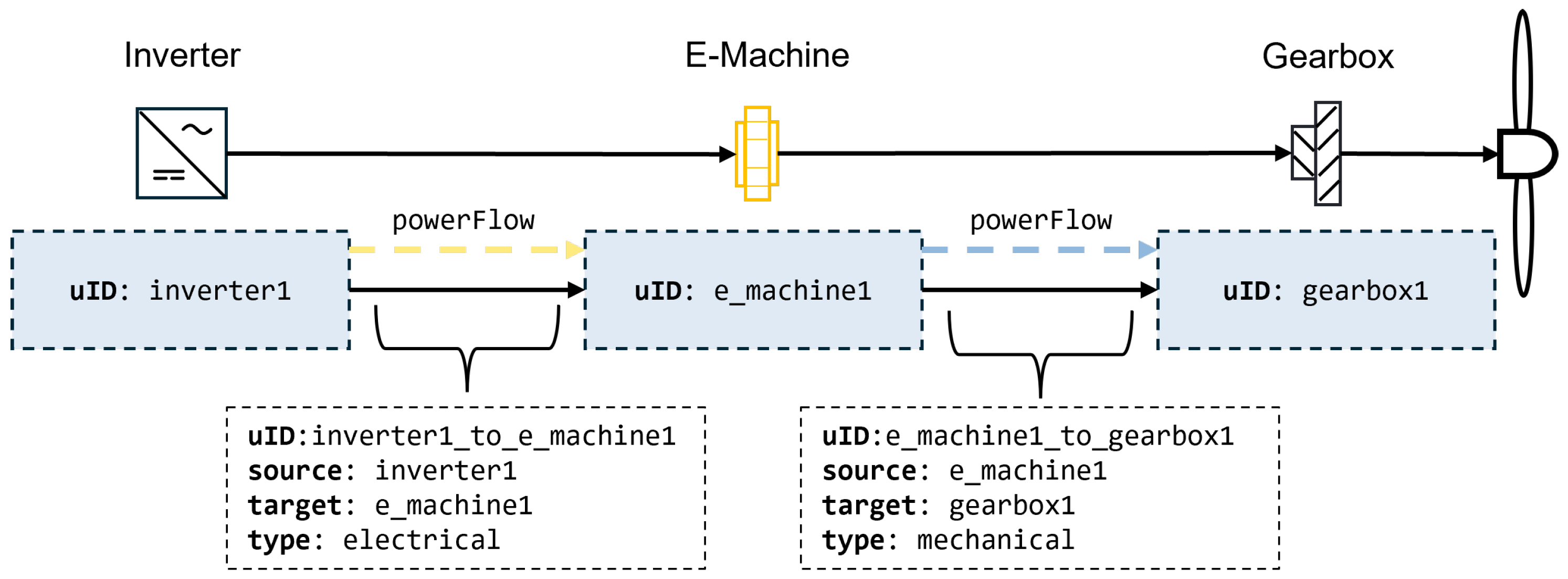
A recent extension of the CPACS data schema includes the description of aircraft systems [5], which will be used in the presented framework. It enables logical and physical representations of the same system, without violating the principle of unambiguous data. Different hierarchical levels of the CPACS are used for the implementation of the system definition: the vehicles level, the aircraft level and the analysis level. At the vehicles level, “library” elements are introduced, representing items relevant for aircraft systems (e.g., batteries, inverters, etc.). These items are named systemElements and can be instantiated repeatedly at aircraft level. By linking the unique identifier (uID) of the systemElement to the respective genericSystem at aircraft level, a physical representation of the system can be achieved (e.g., the components and locations of the system within the aircraft). This perspective is complemented with the logical coupling of the components by assigning directed connections within a systemArchiecture. A connection always consists of a source and a target, which can be represented by instantiated components and linked with the respective componentUIDs. The connection itself can be referenced via a connectionUID. At the lowest hierarchical level, the analysis level, energy or mass flows can be stored on the connections. For different “operational cases”, the flows are represented as powerFlows of differnt types (e.g., electricPower, mechanicalPower or heatFlow).
Figure 1 serves as an illustrative example. A simple systemArchitecure is shown comprising three instantiated components (with their componentUIDs “inverter1”, “e_machine1” and “gearbox1”) and two connections, on which powerFlows are declared. This terminology will be used throughout the paper.
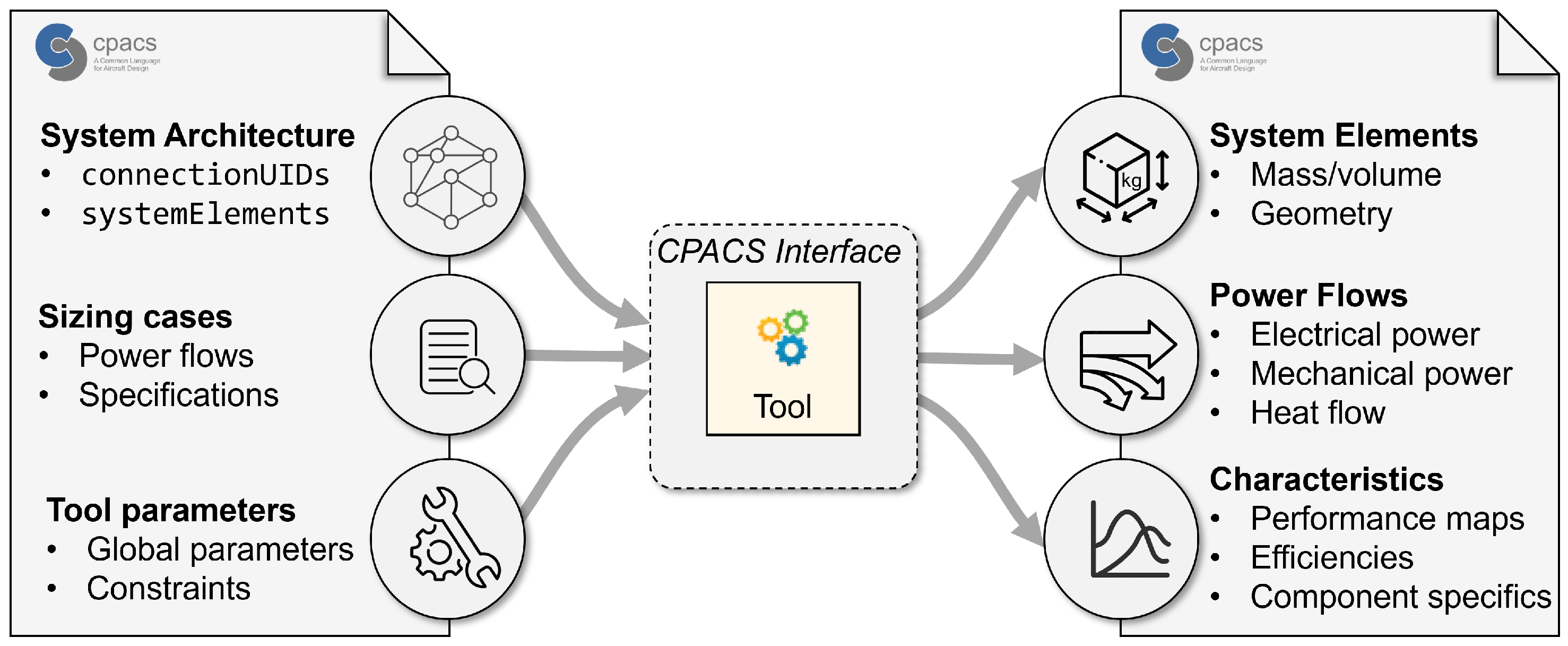
The extension of the system definition forms the basis for representing system components and their interactions within the CPACS. Regarding tools, this requires a standardized approach to ensure that all tools consistently read and write their inputs and outputs to the correct locations within the schema. To this end, a common interface was developed to ensure standardized handling of CPACS data.
Figure 2 gives an overview of the inputs and outputs of the CPACS interface of each sizing tool. The system architecture, namely the components and their connections to each other, is fully represented in the CPACS file that is read by the tool. Together with the componentUID, which the tool retrieves during the sizing workflow, all relevant information needed for sizing is implicitly made available. The componentUID is part of the connectionUID and occurs in either the source or the target node. If the componentUID is found in the source node of a connection, this connection is a physical output of the component (or an input, if it appears in the target node). After searching the system architecture for appearances of the componentUID in all connections, all physical inputs and outputs of the respective component are known. The direction of the connections is defined corresponding to the energy flow or mass flow. Therefore, certain physical outputs, such as the mechanical power delivered by an electric motor, may in fact be an input value for the respective sizing tool. The initial sizing input values are defined in different sizing cases provided by the overall aircraft design. They are represented as powerFlows in the powerBreakdown for different characteristic points, such as take-off, cruise and descent, as well as relevant failure cases. Besides the powerFlows, the sizing cases contain additional specifications such as altitude, mach number and temperature, but also configurational information such as battery state of charge. As all physical input and output connections are known, each associated connectionUID is checked for entries in the powerBreakdown. If a corresponding entry exists, the value of the defined powerFlow is taken as sizing input for the respective component. Based on these inputs, the tool performs its sizing calculation for each sizing case and creates new powerFlow entries linked to the connectionUID that was identified as tool output. The results of component sizing are written into the CPACS structure. The power output is written to the respective powerFlow in the powerBreakdown of each sizing case. The characteristics of the sized components, including mass and volume, are written to the associated systemElement.

3.3. Workflow Execution

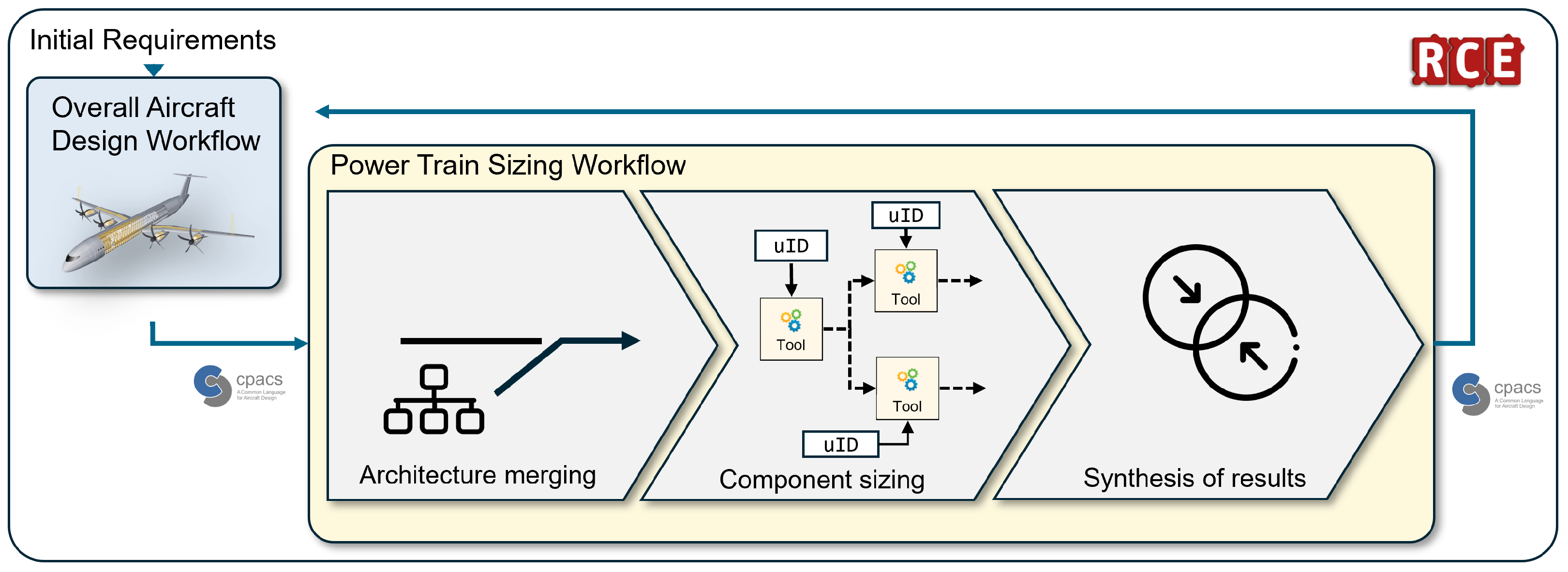
Each of the tools described in Section 3.1 is locally integrated into the integration platform, the RCE. The schematic of the workflow is illustrated in Figure 3.
The powertrain sizing workflow retrieves the CPACS file with the initial design and the associated power requirements from the overall aircraft design workflow. Each component of the power train architecture has a representation of the respective tool in the sizing workflow. Prior to component sizing, the detailed architecture definition of the powertrain is merged into the CPACS file. During workflow execution, each tool receives the componentUID via external input. The input data is then processed according to the process described above and the CPACS file is passed to the next sizing tool after execution. During component sizing, parallel branches of the architecture are sized simultaneously. This requires merging the resulting CPACS files of each branch into the main CPACS file, before the results are fed back to the overall aircraft design workflow.
Currently, the sizing workflow is assembled manually in the RCE. In parallel to the presented framework, workflow generation tools such as MDAx [17] are applied to further automate the workflow assembly. MDAx, the Multidisciplinary Design Analysis and Optimization (MDAO) Workflow Design Accelerator, provides automated formulation of complex MDAO workflows based on structured disciplinary definitions, enabling consistent data exchange and standardized workflow architectures. The user can generate fully specified workflows including component connections, data mappings, and execution sequence using an interactive GUI. These workflows can be exported to the RCE for direct execution. Recent developments in MDAx have allowed for modifying the workflow during execution based on the system architecture being analyzed [18]. This has led to a new branch of MDAO called Dynamic MDAO, which is a crucial component when optimizing different architectures for a system. Dynamic MDAO can be instrumental in automating and accelerating the formulation and execution of powertrain sizing workflows when investigating different architectures at once. Those novel techniques are currently applied to parts of the presented workflow in an application example.

4. Application to Hybrid Electric Powertrain Sizing

The application of the framework to the sizing of a hybrid electric powertrain is presented below.

4.1. Hybrid Electric Powertrain

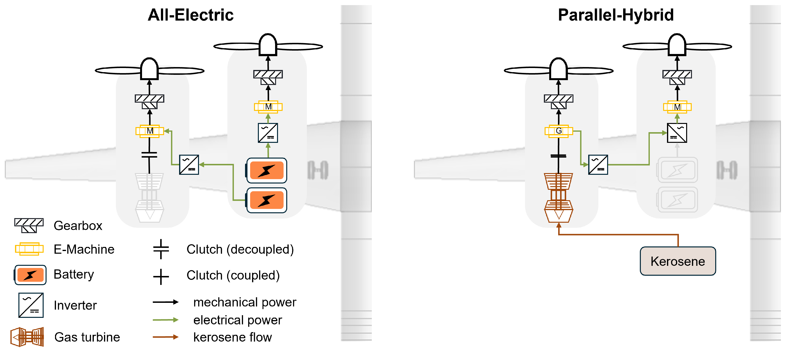
The underlying use case in this paper is the design and analysis of the propulsion system of a 250-seat plug-in hybrid electric powered aircraft concept (PHEP) [6]. The single-aisle aircraft is driven by four propellers and has a design range of 1500 nautical miles and a cruise Mach number of 0.66. On short flight missions of up to 500 km, the aircraft is fully battery electric, exploiting the high battery efficiency. On longer missions of up to 1500 km, the configuration runs in a parallel hybrid mode, where the gas turbines on the outer nacelles provide thrust to the outer propellers while generating electric power for the inner propellers.
The concept is developed within the DLR internal EXACT project (Exploration of Electric Aircraft Concepts and Technologies). According to [1], the aircraft can achieve promising average fleet-level energy efficiency among short-range, single-aisle aircraft, highlighting its potential for further investigation. The basic schematic of the PHEP powertrain is shown in Figure 4. Due to the symmetric propulsion system, only the left wing is illustrated for the two operating modes. The batteries used for propulsion are located in the inner nacelles. In all-electric operation, one battery pack supplies the inner electric machine and the other battery pack supplies the outer electric machine. The gas turbine in the outer nacelle is inactive and mechanically decoupled from the shaft while the electric machine operates in motor mode to drive the propeller. For longer missions, the system is switched to parallel hybrid mode. In this configuration, the kerosene (SAF)-fueled gas turbine is coupled to the propeller shaft and delivers the total propulsion power for both propellers. The electric machine on this shaft operates in generator mode and provides electric energy for the inner electric motor. The outer propeller is driven directly by the gas turbine.

4.2. Sizing Results

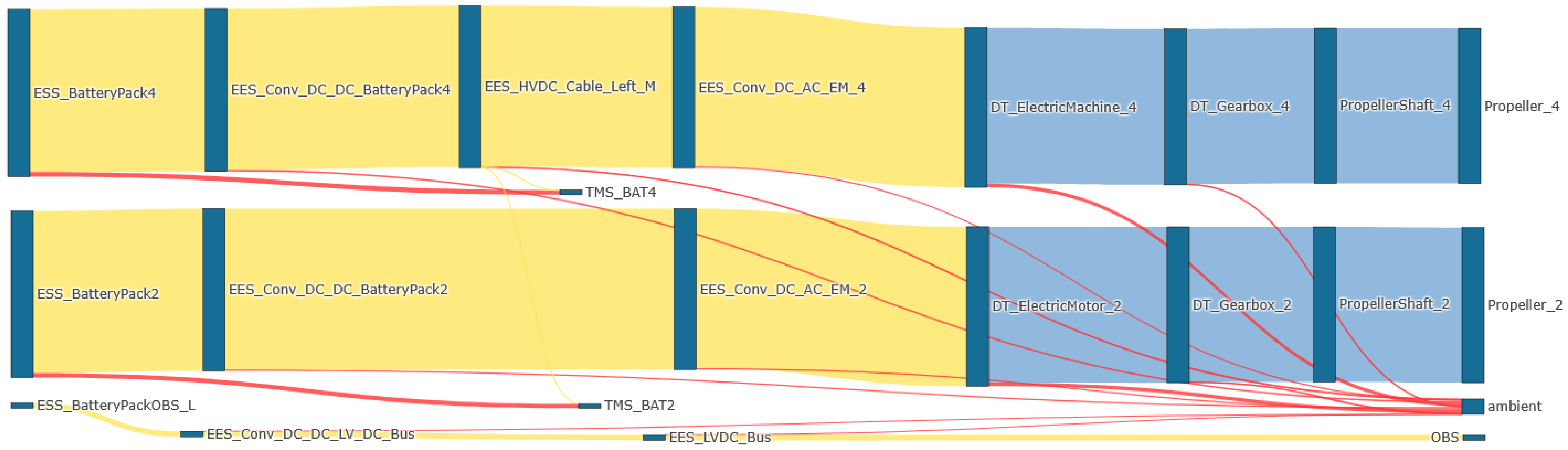
The architecture can now be analyzed in terms of system mass and volume, and the power flows across the connection between the individual components. The powerBreakdown captures the power flows for each analyzed sizing case. For a comprehensive analysis, the visualization dashboard DIANA [19] was employed to display the resulting power flows using Sankey diagrams. Figure 5 shows the power flows during take-off in all-electric operation. The diagram allows detailed analysis of electrical power (yellow), mechanical power (blue), and heat flows (red) exchanged between the individual components. Due to the symmetric power train architecture, only one side of the aircraft is visualized. A dedicated thermal management system is currently only included for the battery, while all remaining heat loads are assigned to the ambient. This provides a clear overview of the magnitude and the location of the heat loads within the aircraft, supporting further investigation and refinement of the thermal management architecture.

5. Conclusions

Including detailed expert knowledge into the aircraft design process at an early stage is essential to analyze aircraft concepts with novel propulsion systems. The framework presented in this paper enables the integration of engineering routines from distributed development teams into the detailed design of a powertrain architecture. The system definition in the common data exchange model, the CPACS, is used to represent the overall powertrain system architecture to capture the physical interconnections of the individual system components. The methods used for component sizing are provided by different partners and are integrated into a process integration platform for workflow execution. To ensure consistent data processing of the inputs and outputs of each tool, a standardized CPACS interface is wrapped around each tool. The framework is demonstrated on the powertrain of a plug-in hybrid electric powered aircraft concept. An overall powertrain sizing workflow is successfully established based on the requirements from the overall aircraft design. The results of powertrain sizing are merged and fed back to the overall aircraft design workflow. Using this framework, detailed component design can be integrated into the preliminary aircraft design process, striving for a robust technology assessment at an early development stage.

Author Contributions

Conceptualization, N.W. and T.B.; methodology, N.W., T.B. and S.G.; formal analysis, N.W.; investigation, N.W. and T.B.; visualization, N.W.; writing—original draft preparation, N.W., T.B. and S.G.; writing—review and editing, N.W. and T.B. All authors have read and agreed to the published version of the manuscript.

Funding

This research was funded by the DLR internal project EXACT 2 (Exploration of Electric Aircraft Concepts and Technologies 2).

Institutional Review Board Statement

Not applicable.

Informed Consent Statement

Not applicable.

Data Availability Statement

The data presented in this study are available upon request from the corresponding author.

Acknowledgments

The authors would like to thank the entire project team for their valuable input; technical discussions; and the methods, tools and data provided throughout the development of this work. Further thanks go to Florian Franke for developing and providing the gearbox sizing tool and former colleague Yannic Cabac for developing and providing the electric motor tool.

Conflicts of Interest

The authors declare no conflicts of interest.

References

  1. Atanasov, G.; Silberhorn, D. EXACT Sustainable Aircraft Concepts Results and Comparison. 2025. Available online: https://publikationen.dglr.de/?tx_dglrpublications_pi1%5bdocument_id%5d=630388 (accessed on 10 November 2025). [CrossRef]
  2. Moerland, E.; Deinert, S.; Daoud, F.; Dornwald, J.; Nagel, B. Collaborative Aircraft Design Using an Integrated and Distributed Multidisciplinary Product Development Process. In Proceedings of the 30th ICAS Conference, Daejon, Republic of Korea, 25–30 September 2016. [Google Scholar]
  3. Boden, B.; Flink, J.; Först, N.; Mischke, R.; Schaffert, K.; Weinert, A.; Wohlan, A.; Schreiber, A. RCE: An Integration Environment for Engineering and Science. SoftwareX 2021, 15, 100759. [Google Scholar] [CrossRef]
  4. Alder, M.; Moerland, E.; Jepsen, J.; Nagel, B. Recent Advances in Establishing a Common Language for Aircraft Design with CPACS. In Proceedings of the Aerospace Europe Conference 2020, Bordeaux, France, 25–28 February 2020. [Google Scholar]
  5. Burschyk, T.; Alder, M.; Mancini, A.; Bielsky, T.; Kriewall, V.; Thielecke, F.; Nagel, B. Introduction of a System Definition in the Common Parametric Aircraft Configuration Schema (CPACS). Aerospace 2025, 12, 373. [Google Scholar] [CrossRef]
  6. Atanasov, G.; Silberhorn, D. Bridging Scale and Sustainability: A Battery-Electric Aircraft with Range Extenders for Flexible Short- to Medium-Range Operations. In Proceedings of the 15th EASN International Conference, Madrid, Spain, 14–17 October 2025. [Google Scholar]
  7. Alder, M.; Liersch, C.; Hepperle, M.; Maierl, R.; Deinert, S.; Kleinert, J.; Siggel, M.; Kohlgrüber, D.; Moerland, E.; Nagel, B. 20 years of CPACS: A Brief History and Future Vision of Establishing a Common Language for Aircraft Design. In Proceedings of the Deutscher Luft- und Raumfahrt Kongress (DLRK) 2024, Hamburg, Germany, 30 September–2 October 2024. [Google Scholar]
  8. Brown, G.V.; Kascak, A.F.; Ebihara, B.; Johnson, D.; Choi, B.; Siebert, M.; Buccieri, C. NASA Glenn Research Center Program in High Power Density Motors for Aeropropulsion; Technical Report; NASA: Washington, DC, USA, 2005.
  9. Reynolds, C. Advanced Prop-Fan Engine Technology (APET) Single-and Counter-Rotation Gearbox/Pitch Change Mechanism; Technical Report; NASA: Washington, DC, USA, 1985.
  10. Vratny, P.C.; Hornung, M. Sizing Considerations of an Electric Ducted Fan for Hybrid Energy Aircraft. Transp. Res. Procedia 2018, 29, 410–426. [Google Scholar] [CrossRef]
  11. Marvin, R.H.; Helenbrook, B.T.; Visser, K.D. Predicting motor and generator maximum torque as a function of mass. In 2017 IEEE International Electric Machines and Drives Conference (IEMDC); IEEE: New York, NY, USA, 2017; pp. 1–6. [Google Scholar]
  12. Sirimanna, S.; Thanatheepan, B.; Lee, D.; Agrawal, S.; Yu, Y.; Wang, Y.; Anderson, A.; Banerjee, A.; Haran, K. Comparison of electrified aircraft propulsion drive systems with different electric motor topologies. J. Propuls. Power 2021, 37, 733–747. [Google Scholar] [CrossRef]
  13. Albrecht, P.; Bänsch, C.; Murschenhofer, D. Means to Improve Fuel Cell Aircraft Performance Through Hybridization and Design Mission Constraints; Deutsche Gesellschaft für Luft-und Raumfahrt-Lilienthal-Oberth eV: Bonn, Germany, 2025. [Google Scholar] [CrossRef]
  14. Kugener, J.; Kazula, S. Preliminary Design and Evaluation of Inverter Power Density and Reliability in Electric Aircraft Propulsion Systems. In 2024 International Exhibition and Conference for Power Electronics, Intelligent Motion, Renewable Energy and Energy Management, PCIM Europe 2024; PCIM Europe Conference Proceedings; VDE: Offenbach, Germany, 2024. [Google Scholar]
  15. Kugener, J.; Maddula, M.S.C.; Kazula, S.; de Graaf, S. Conceptual Study on DC-DC Converter Topologies in Battery-Fuel Cell Electric Aircraft Propulsion. In Proceedings of the 2025 IEEE/AIAA Transportation Electrification Conference and Electric Aircraft Technologies Symposium, ITEC+EATS 2025, Anaheim, CA, USA, 18–20 June 2025. [Google Scholar]
  16. Schröder, M.; Becker, F.; Gentner, C. Optimal design of proton exchange membrane fuel cell systems for regional aircraft. Energy Convers. Manag. 2024, 308, 118338. [Google Scholar] [CrossRef]
  17. Garg, S.; Bussemaker, J.; Boggero, L.; Nagel, B. MDAx: Enhancements in a Collaborative MDAO Workflow Formulation Tool. In Proceedings of the 34th Congress of the International Council of the Aeronautical Sciences, ICAS 2024, Florence, Italy, 9–13 September 2024. [Google Scholar]
  18. Garg, S.; Garcia Sanchez, R.; Bussemaker, J.H.; Boggero, L.; Nagel, B. Dynamic Formulation and Execution of MDAO Workflows for Architecture Optimization. In Proceedings of the AIAA Aviation Forum and Ascend 2024, Reston, VA, USA, 29 July–2 August 2024. [Google Scholar] [CrossRef]
  19. García Sánchez, R.; Mancini, A.; Nugnes, V.; Fröhler, B.M.; Gerlinger, B. DIANA: Data Interactive Analysis and Navigation Application. In Proceedings of the AIAA Aviation Forum and Ascend 2025, Reston, VA, USA, 22–24 July 2025. [Google Scholar] [CrossRef]
Figure 1. Illustrative example of the terminology used for the CPACS system definition.
Engproc 133 00042 g001
Figure 2. Inputs and outputs of the CPACS interface of each tool.
Engproc 133 00042 g002
Figure 3. Illustration of the powertrain sizing workflow execution.
Engproc 133 00042 g003
Figure 4. PHEP powertrain and operating scenarios.
Engproc 133 00042 g004
Figure 5. Power breakdown during all-electric operation.
Engproc 133 00042 g005
Disclaimer/Publisher’s Note: The statements, opinions and data contained in all publications are solely those of the individual author(s) and contributor(s) and not of MDPI and/or the editor(s). MDPI and/or the editor(s) disclaim responsibility for any injury to people or property resulting from any ideas, methods, instructions or products referred to in the content.