1. Introduction
The transition toward sustainable aviation requires novel aircraft architecture capable of significantly reducing emissions, fuel consumption, and noise. European strategic roadmaps, such as Clean Aviation’s Strategic Research and Innovation Agenda (SRIA) and the Destination 2050 initiative, identify hybrid-electric propulsion as a key enabler for achieving net-zero targets by 2050.
In this context, the HERFUSE project [
1] (Hybrid-Electric Regional Fuselage & Empennages), funded under the Clean Aviation program [
2], focuses on the conceptual and preliminary design of fuselage and empennage solutions for next-generation regional aircraft. The project’s Use Case B (UCB) demonstrator integrates distributed hybrid-electric propulsion, liquid-hydrogen storage, and advanced composite structures, introducing new structural and aeroelastic challenges [
3].
Hybrid-electric architectures [
4,
5,
6] modify the empennage loading environment through asymmetric distributed propulsion effects, modified fuselage–tail interfaces due to hydrogen storage, and rigid mass-reduction constraints [
7]. These factors increase the need for fast, robust, and simulation-driven structural design tools. Traditional finite element workflows, however, are often rigid and time-consuming, limiting their suitability for early-stage design iterations.
To address these limitations, a fully parametric finite element model has been developed in HERFUSE using ANSYS APDL. The workflow automates geometry generation, material assignment, distributed load application, and both modal and static analyses through a compact and reconfigurable scripting environment.
This paper presents the development of the parametric APDL model, its integration with external load-processing tools, and its verification through comprehensive structural and modal consistency checks. The workflow provides a foundation for future multidisciplinary design and optimization (MDO) activities within HERFUSE and supports a reliable structural assessment for hybrid-electric aircraft configurations [
8].
2. Materials & Methods
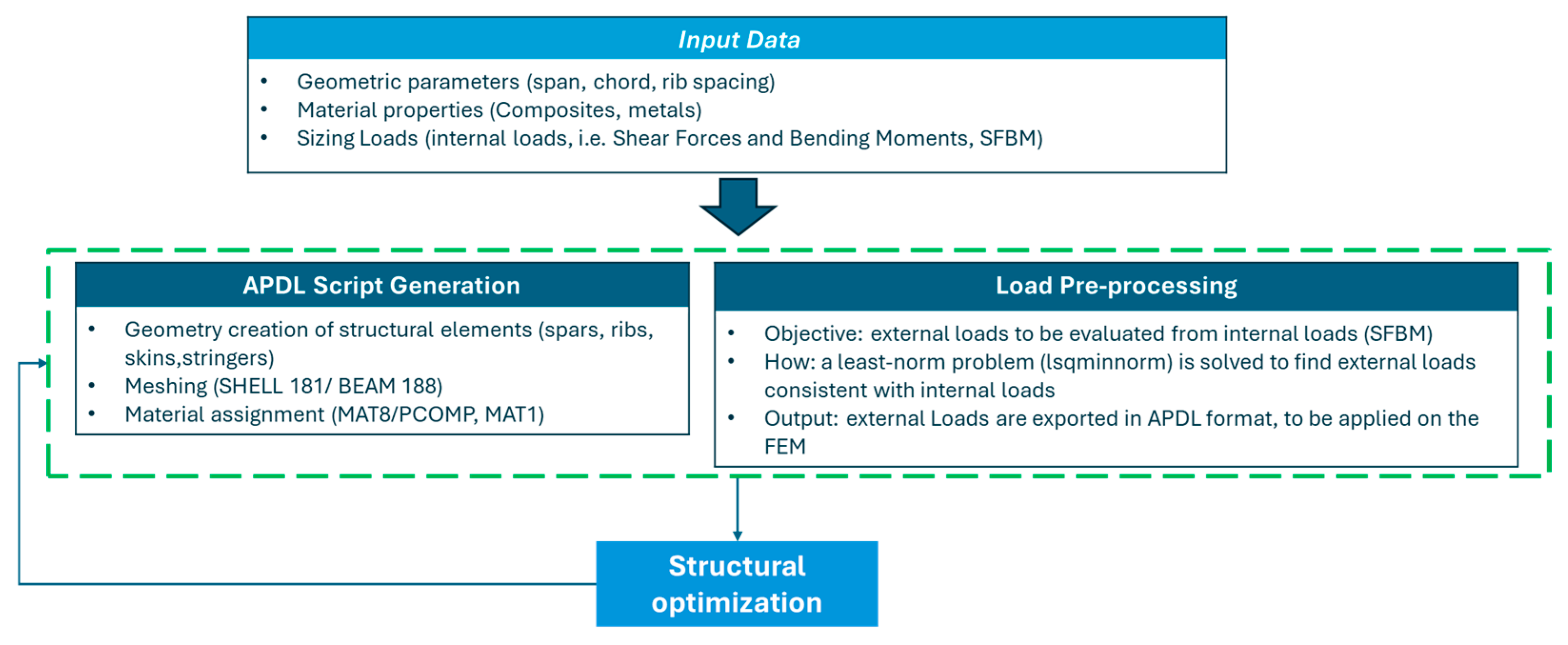
The methodology combines a parametric APDL, script implemented in ANSYS Mechanical 2023 R1 (ANSYS Inc., Canonsburg, PA, USA), model with an external load-processing tool to enable rapid structural evaluation. Input data include geometric parameters, material properties, and internal sizing loads derived from the SFBM procedure. Based on these inputs, the APDL module automatically generates the structural model, creating geometry, mesh, and material layups through fully scripted commands; see
Figure 1. In parallel, a load pre-processing step reconstructs the external spanwise loads by solving a least-norm problem to match the target internal shear forces and bending moments. The resulting load sets are then exported in APDL format and applied to the parametric model, forming the basis for subsequent structural optimization analyses.
2.1. Parametric Capabilities
A key outcome of this work is the demonstration of the parametric flexibility achieved within the FEM framework [
9,
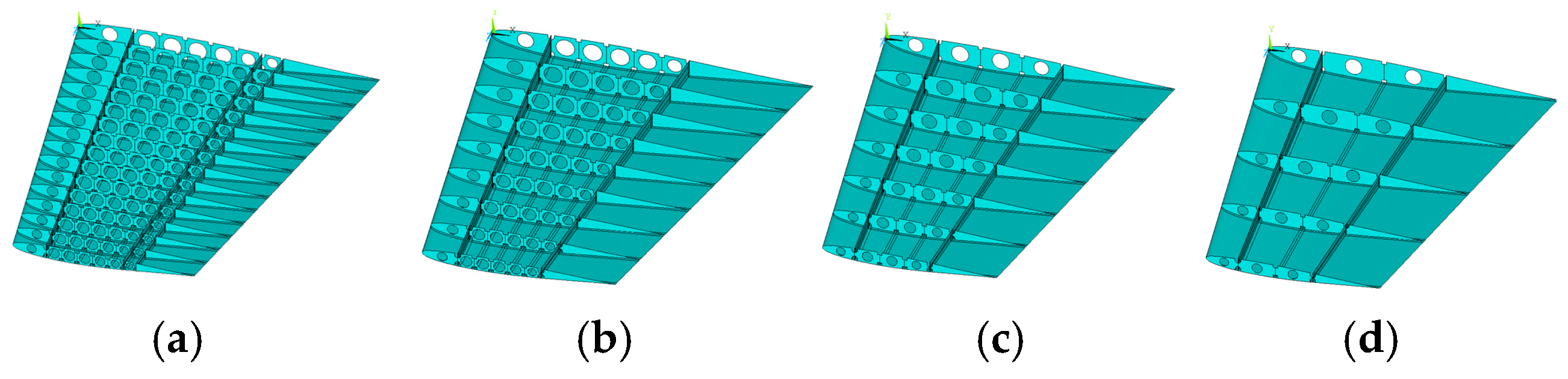
10]. The APDL script enables the modification of structural features, such as the number of ribs, stringer spacing, and thicknesses, or the selection of different load cases without requiring manual intervention. This high level of reconfigurability significantly reduces the turnaround time of each design iteration, establishing the parametric FEM as an effective platform for future multidisciplinary design optimization activities.
The parametric model is intended to be integrated into optimization loops driven by evolutionary algorithms, enabling systematic exploration of trade-offs among mass reduction, structural stiffness and overall performance across the structural layout illustrated in
Figure 2 and summarized in
Table 1. This framework will support automated assessment of multiple design configurations and facilitate data-driven decision-making during early development. In this context, the parametric FEM serves as a precursor to provide a robust foundation for subsequent refinement of empennage structural design [
11,
12,
13].
2.2. Model Description and Implementation
The main geometric characteristics of the horizontal tailplane (HTP) are as follows: a wingspan of 3.978 m, a mean aerodynamic chord of 0.697 m, a dihedral angle of 7°, and a maximum relative thickness of 12% (see
Table 2). The airfoil is an ADS-type section, selected for its favorable stability and manufacturability properties. Structurally, the HTP includes 14 equally spaced ribs with lightening cutouts, three spars (one of which is a rear closure spar for enhanced torsional stiffness), eight stringers (four per skin), and composite external skins. This configuration serves as the reference baseline for developing the parametric finite element model (FEM).
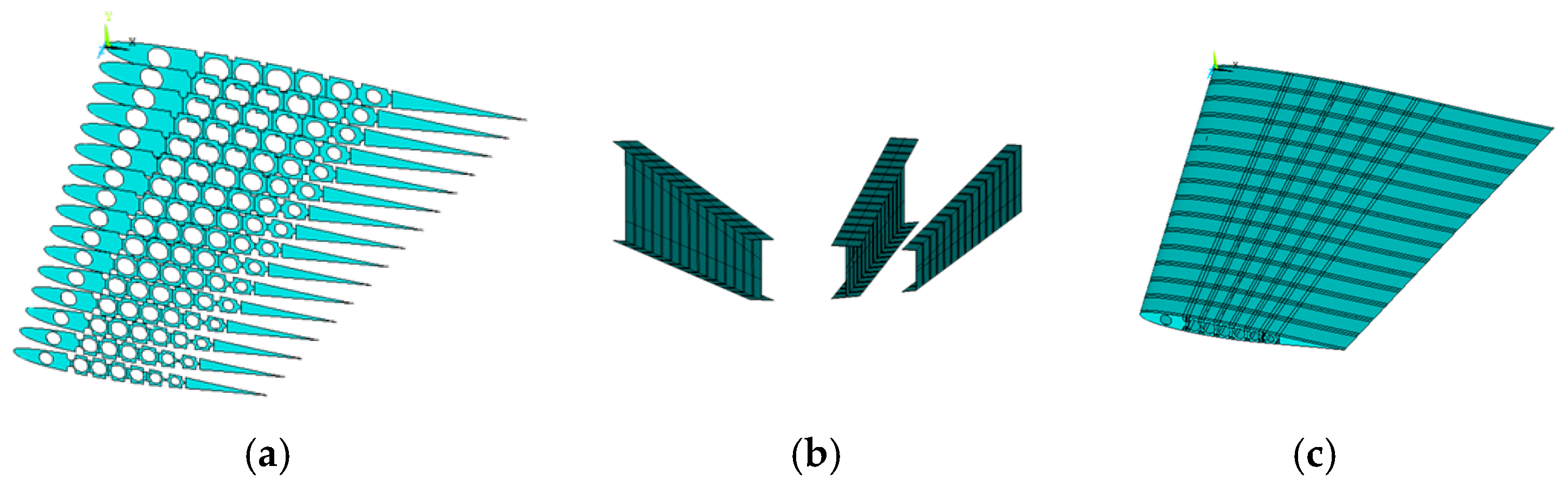
The geometry is constructed using loops and conditional blocks that iterate along the wingspan to generate ribs, spars, and skin surfaces [
14,
15]. Cut operations are performed to model rib opening (
Figure 3).
The geometry is discretized using:
SHELL181 elements for ribs, spars, and skins.
BEAM188 elements for stringers, with section properties defined parametrically.
The composite material is not modeled ply-by-ply; instead, an equivalent isotropic material is adopted, with its properties derived from the laminate stacking sequence and ply data provided as project inputs. The use of equivalent isotropic material is consistent with the conceptual and preliminary scope of this work. This modeling assumption captures the global stiffness and mass distribution of the composite structure while preserving the parametric flexibility required for rapid design iterations. Although ply-level anisotropy and local stress concentrations are not explicitly modeled, the equivalent properties derived from the reference laminate provide a representative description of the overall structural behavior. This approach is therefore suitable for early-stage comparative evaluation of alternative structural layouts.
The APDL implementation enables each component to be generated sequentially within the script [
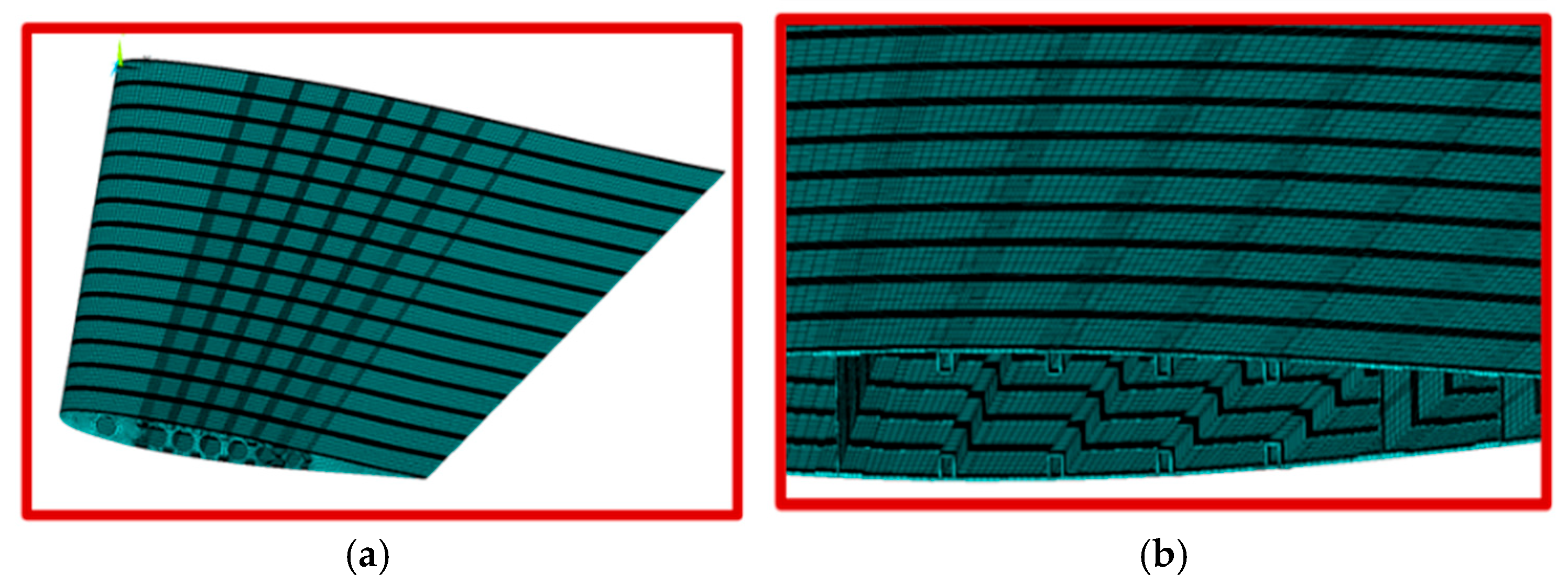
16]. Mesh density is controlled through a parametric variable that can be adjusted depending on the required level of fidelity (
Figure 4). An average element size of approximately 2 mm is selected to balance computational efficiency with adequate resolution of the stress fields [
17,
18,
19,
20].
Boundary conditions are applied at the HTP–VTP interface, specifically at the root of the central lower spar, ensuring correct representation of the empennage connection.
2.3. Loads Application
Loads were applied using a custom numerical procedure developed within the project, named SFBM-HERFUSE developed in-house in MATLAB (The MathWorks Inc., Natick, MA, USA). The method converts each load case into spanwise-distributed forces and moments suitable for a semi-flexible beam model, a representation of HTP.
The algorithm reconstructs the load distribution section by section, moving from the tip to the root of the HTP. The script first initializes the workspace and defines the number of spanwise sections at which loads will be applied. A set of load cases is then imported from a formatted text file and reshaped into a matrix, where each row contains six parameters per case (e.g., force and moment coefficients).
The user selects a specific load case by index, after which the corresponding vertical force and bending/torsional moment coefficients are extracted.
Spanwise distributions for forces and moments are generated using predefined polynomial expressions (quadratic and cubic), which act as basic functions for representing the load distribution.
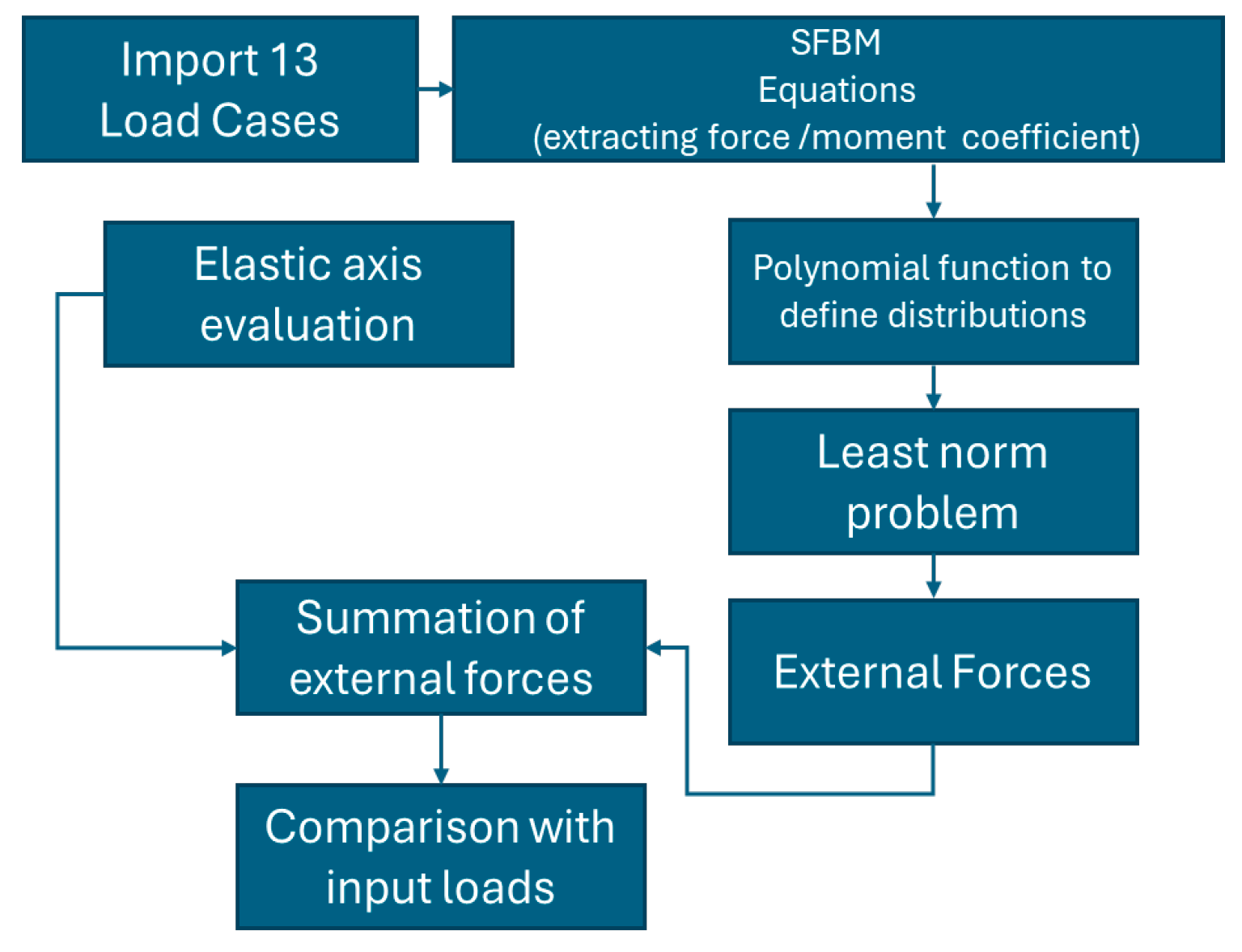
As illustrated in
Figure 5, the procedure consists of:
Importing 13 aerodynamic load cases;
Extracting vertical force and bending/torsional moment coefficients;
Constructing load distributions using polynomial basis functions (quadratic and cubic);
Solving a least-norm problem to enforce global equilibrium;
Exporting the resulting distributed loads into a structured file for FEM application.
Figure 5.
Scheme of procedure SFBM.
Figure 5.
Scheme of procedure SFBM.
This integrated approach enables accurate and fully automated load application in the FE model, ensuring consistent simulation of the interaction between the HTP and VTU structures.
It also guarantees not only global equilibrium but also a realistic distribution of bending and torsional effects along the span, which is essential for capturing the correct stiffness requirements and aeroelastic behavior.
3. Results
Verification of the parametric FEM has been performed through a set of modal and static analyses in ANSYS Mechanical 2023 R1 (ANSYS Inc., Canonsburg, PA, USA).
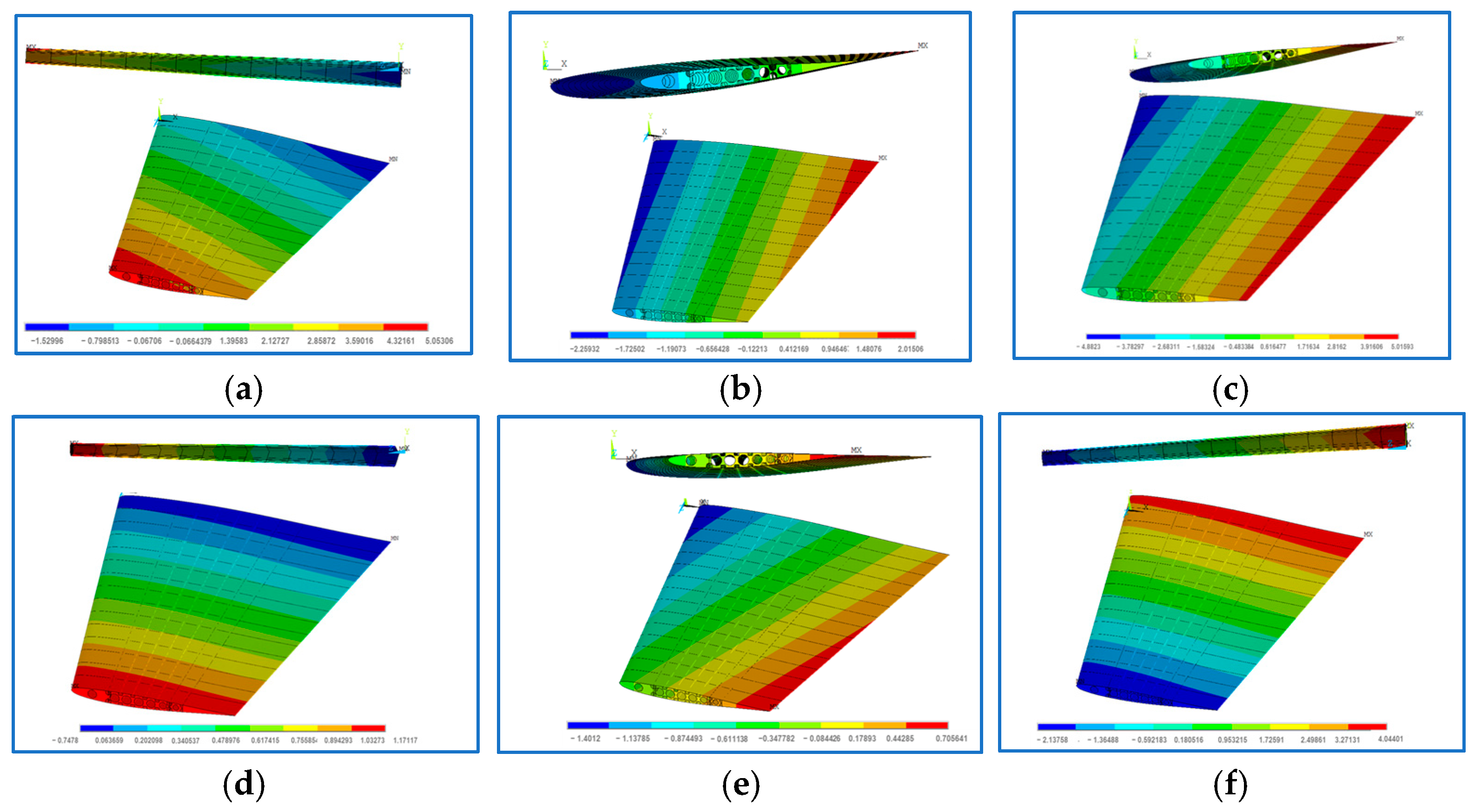
At first, in the free-free condition, the first six rigid-body modes (
Figure 6) were correctly identified, followed by the expected flexible bending and torsional modes. The corresponding frequencies are consistent with preliminary predictions, confirming that the model captures the correct dynamic behavior of the empennages (
Table 3).
Then, six simulations were performed by applying a unit displacement in each degree of freedom (UX, UY, UZ, ROTX, ROTY, ROTZ) at a central node, with all other constraints removed. The resulting nodal responses matched the imposed displacements, demonstrating correct assembly of the global stiffness matrix.
Finally, static analyses under 1 g loads were also carried out to confirm overall model consistency. Maximum displacements fell within the expected range of a few millimeters, and stress levels remained below the material’s allowable range. The strength ratio, defined as the ratio between allowable and applied stresses, was greater than unity across all components, indicating that the conceptual structural design meets the initial strength requirements (See
Table 4,
Table 5 and
Table 6).
4. Conclusions
A fully parametric FEM workflow for the structural design of the horizontal tailplane has been developed using ANSYS Mechanical 2023 R1 (ANSYS Inc., Canonsburg, PA, USA) APDL scripting. The workflow automates geometry creation, meshing, material assignment, load application, and analysis, significantly reducing manual effort and enabling rapid iterations. The parametric modeling capabilities allow flexible adjustment of key structural variables, supporting both preliminary assessments and optimization studies.
Preliminary verification checks, including free-free modal analysis, unit displacement tests, and gravity load verification, confirmed the physical consistency and numerical accuracy of the FE model. The resulting framework provides a reliable, repeatable, and efficient tool to support early-stage structural design, with potential for application across different aircraft components or multidisciplinary environments.
The methodology can be extended to other components, such as control surfaces, wing, vertical tailplane and fuselage, and can be integrated into broader MDO frameworks.
Author Contributions
Conceptualization, C.P.; methodology, C.P. and G.P.; software, A.S. and D.C.; validation, C.P., G.P. and A.C.; formal analysis, C.P.; investigation, C.P.; resources, M.B.; data curation, A.C.; writing—original draft preparation, C.P.; writing—review and editing, A.C. and M.B.; visualization, A.S.; supervision, G.P.; project administration, A.C.; funding acquisition, M.B. All authors have read and agreed to the published version of the manuscript.
Funding
This research was funded by the Clean Aviation Joint Undertaking under the European Union’s Horizon Europe research and innovation program, Project HERFUSE—Hybrid-Electric Regional Fuselage & Empennages, Grant Agreement No. 101140567. The APC was funded by the Clean Aviation Joint Undertaking.
Institutional Review Board Statement
Not applicable.
Informed Consent Statement
Not applicable.
Data Availability Statement
Data supporting the findings of this study are available from the corresponding author upon reasonable request. Some data may not be publicly available due to industrial confidentiality constraints.
Acknowledgments
This work has been carried out in the framework of the HERFUSE project, supported by the Clean Aviation Joint Undertaking and its members under the European Union Horizon Europe program.
Conflicts of Interest
The authors declare no conflicts of interest.
Abbreviations
The following abbreviations are used in this manuscript:
References
- HERFUSE Project. Hybrid-Electric Regional Fuselage & Empennages. Clean Aviation Joint Undertaking, Horizon Europe, Grant Agreement No. 101140567, 2024. Available online: https://herfuse.eu/ (accessed on 1 October 2025).
- Clean Aviation Joint Undertaking. Clean Aviation Projects; Horizon Europe: Brussels, Belgium, 2025. [Google Scholar]
- European Commission. FASTER-H2 Project: Fuselage, Rear Fuselage and Empennage with Cabin and Cargo Architecture Solution Validation and Technologies for H2 Integration. Horizon Europe, Grant Agreement No. 101101978, 2025. Available online: https://cordis.europa.eu/project/id/101101978 (accessed on 1 October 2025).
- Shan, W.; Bao, S.; Lin, S.; Kang, L. Hybrid Electric Propulsion Design and Analysis Based on Regional Aircraft Mission. World Electr. Veh. J. 2025, 16, 212. [Google Scholar] [CrossRef] [Scilit]
- Gil, A.A.; Silva, H.L. Hybrid-Electric Aircraft: Conceptual Design, Structural and Aeroelastic Analyses; Universidade Federal de Uberlândia: Uberlândia, Brazil, 2017. [Google Scholar]
- Etherington, T.; Ghatas, R.W.; Arthur, T.; Hill, M.; Litt, J. Flight Deck Design of a Hybrid Turbine/Electric Aircraft (SUSAN Program); NASA Langley Research Center: Hampton, VA, USA, 2025. [Google Scholar]
- Yu, F.; Chen, J.; Gao, P.; Kong, Y.; Sun, X.; Wang, J.; Chen, X. A Review of Hybrid-Electric Propulsion in Aviation: Modeling Methods, Energy Management Strategies, and Future Prospects. Aerospace 2025, 12, 895. [Google Scholar] [CrossRef] [Scilit]
- Nasoulis, C.P.; Gkoutzamanis, V.G.; Kalfas, A.I. Multidisciplinary Conceptual Design for a Hybrid-Electric Commuter Aircraft. Aeronaut. J. 2022, 126, 1242–1264. [Google Scholar] [CrossRef] [Scilit]
- Mukhopadhyay, V.; Ozoroski, T.A.; McMillin, M.L. Structural Configuration Analysis of Advanced Flight Vehicle Concepts with Distributed Hybrid-Electric Propulsion; NASA Langley Research Center Report: Hampton, VA, USA, 2019. [Google Scholar]
- Pustina, L.; Mastroddi, F.; Della Vecchia, P.; Cerino, G. Structural Design of Next-Generation Regional Green Aircraft. In Proceedings of ICAS 2024, Florence, Italy, 9–13 September 2024; International Council of the Aeronautical Sciences: Bonn, Germany, 2024. [Google Scholar]
- Noviello, M.C.; Dimino, I.; Ameduri, S.; Concilio, A. Conceptual Design and Topology Optimization of a Compliant Morphing Flap for Next Generation Hybrid-Electric Regional Aircraft. In Proceedings of the ICAS 2024, Florence, Italy, 9–13 September 2024. [Google Scholar]
- Weisshaar, J. Morphing Aircraft Technology—New Shapes for Aircraft Design; NATO RTO Report; NATO Science and Technology Organization: Neuilly-sur-Seine, France, 2013. [Google Scholar]
- Rendón, M.A.; Sánchez, C.; Gallo Muñoz, J.; Anzai, A. Aircraft Hybrid-Electric Propulsion: Development Trends, Challenges and Opportunities. J. Control Autom. Electr. Syst. 2021, 32, 1244–1268. [Google Scholar] [CrossRef] [Scilit]
- Yin, Y.-L.; Zhang, K.-S.; Qiao, H.-L.; Che, A.-L.; Han, Z.-H. Fast Parametric Structure Modeling for Variety of Aircraft Configurations. In Proceedings of the 33rd International Council of the Aeronautical Sciences (ICAS), Stockholm, Sweden, 9–13 September 2024. [Google Scholar]
- Horvath, B.L. Aircraft Conceptual Structural Design Using the AMMIT Structural Analysis Tool; NASA Technical Report; NASA: Washington, DC, USA, 2020. [Google Scholar]
- Naziri, A. Scalable Structural Analysis Through Automated APDL Scripting and Python Integration. Master’s Thesis, Lappeenranta–Lahti University of Technology, Lappeenranta, Finland, 2025. [Google Scholar]
- Du, Y.; Liu, Z.; Shen, M.; Wu, J.; Zhang, K.; Jiang, C.; Zhong, J. An Efficient Parametric Modeling, Evaluation and Optimization Strategy for Aerodynamic Configuration Design of eVTOL Aircraft. Aerosp. Res. Commun. 2025, 3, 14986. [Google Scholar] [CrossRef] [Scilit]
- Kleinert, J.; Boden, B.; Reiswich, A. Advanced Collaborative Aircraft Design: Complementing CPACS with Knowledge-Based Engineering and Custom Geometry Parametrization; DGLR Publikationen: Bonn, Germany, 2024. [Google Scholar]
- Ansys Inc. Ansys Parametric Design Language Guide; Release 2024 R2, Ansys Documentation; ANSYS Inc.: Canonsburg, PA, USA, 2024. [Google Scholar]
- PADT Inc. APDL—Introduction to the ANSYS Parametric Design Language. In PADT Simulation Guide; PADT Inc.: Tempe, AZ, USA, 2023. [Google Scholar]
| Disclaimer/Publisher’s Note: The statements, opinions and data contained in all publications are solely those of the individual author(s) and contributor(s) and not of MDPI and/or the editor(s). MDPI and/or the editor(s) disclaim responsibility for any injury to people or property resulting from any ideas, methods, instructions or products referred to in the content. |