Proceeding Paper

Thermal Management Concepts: Application Examples Using a Convective Heat Transfer Measurement Sensor †
Fraunhofer Institute for Building Physics IBP, 83626 Valley, Germany
*
Author to whom correspondence should be addressed.
Presented at the 15th EASN International Conference, Madrid, Spain, 14–17 October 2025.
Eng. Proc. 2026, 133(1), 143; https://doi.org/10.3390/engproc2026133143
Published: 14 May 2026

Abstract

The shift toward more electric aircraft has intensified thermal management challenges due to increased heat load from electrical actuators, power electronics and energy storage systems concentrated within confined fuselage bays. A Conventional Environmental Control System (ECS) alone is not sufficient to dissipate such high localized heat loads. This creates the need for innovative heat dissipation and heat reuse strategies. This paper presents two thermal management concepts evaluated at the Fraunhofer Flight Test Facility. The first, developed in the ORCHESTRA project, integrates a bilge skin heat exchanger with modified ventilation to dissipate elevated heat loads. The second, under investigation in the TheMa4HERA project, focuses on reusing avionics heat to warm the FWD cargo hold, thereby reducing ECS power demand. Both concepts depend on convective heat exchange, characterized using Fraunhofer’s Convective Heat Transfer Meter (CHM) to determine key heat transfer coefficients. In parallel, an aircraft-level thermal model was developed, validated against experimental data and subsequently used for virtual demonstration of a ground test scenario.

1. Introduction

The shift to electrically driven aircraft systems improves efficiency by reducing mechanical complexity and eliminating hydraulic and pneumatic lines. However, it concentrates heat in localized electronic modules rather than dispersing it along traditional piping, causing high thermal loads in confined areas like avionics and equipment bays. Conventional ECSs cannot manage these intense heat fluxes, especially on the ground, without ram air cooling. Managing these concentrated thermal loads is now a major challenge for more electric aircraft [1,2,3].
To address these challenges, two thermal management concepts are being evaluated at the Fraunhofer Flight Test Facility. The first concept, developed within the ORCHESTRA project, focused on heat dissipation through a bilge skin heat exchanger during flight, supplemented by modified avionics ventilation on the ground. The associated experimental campaign investigated the increased avionics heat loads caused by integrating a dual active bridge and an AC/DC converter into the system architecture. Both laboratory flight condition tests and simulations assessed whether adjustments to the existing ventilation system could accommodate these additional loads.
Within the ORCHESTRA project [4,5], a detailed aircraft-level thermal model was progressively enriched and validated using data from tests conducted in the aircraft mockup equipped with ventilation, avionics heat loads and a skin heat exchanger. During cold-condition in-flight tests (−25 °C skin temperature), the combined operation of cabin ventilation, recirculation extraction fans and avionics heat sources enabled a comprehensive assessment of the thermal management strategy. A key innovation was the use of the Fraunhofer-developed Convective Heat Transfer Meter (CHM), which measures the convective heat transfer coefficient. Comparison with experimental results confirmed the accuracy of the thermal model in predicting temperature distributions throughout the cabin, cockpit and avionics bay. Subsequent simulations under hot ground conditions revealed that skin heat exchangers provide minimal dissipation on the ground, emphasizing the need for additional ventilation strategies.
The second thermal management concept, currently being evaluated within the TheMa4HERA project [6], focuses on avionics heat reuse rather than dissipation. Here, the waste heat from the avionics bay is intentionally directed beneath the FWD cargo hold to warm the cargo hold floor and, hence, warm up the FWD cargo hold, potentially reducing ECS power demand during cold operations. This paper describes the ongoing integration of this test setup at the Fraunhofer Flight Test Facility.

2. Experimental Methodology: Heat Dissipation Through Skin Heat Exchanger

2.1. Flight Test Facility

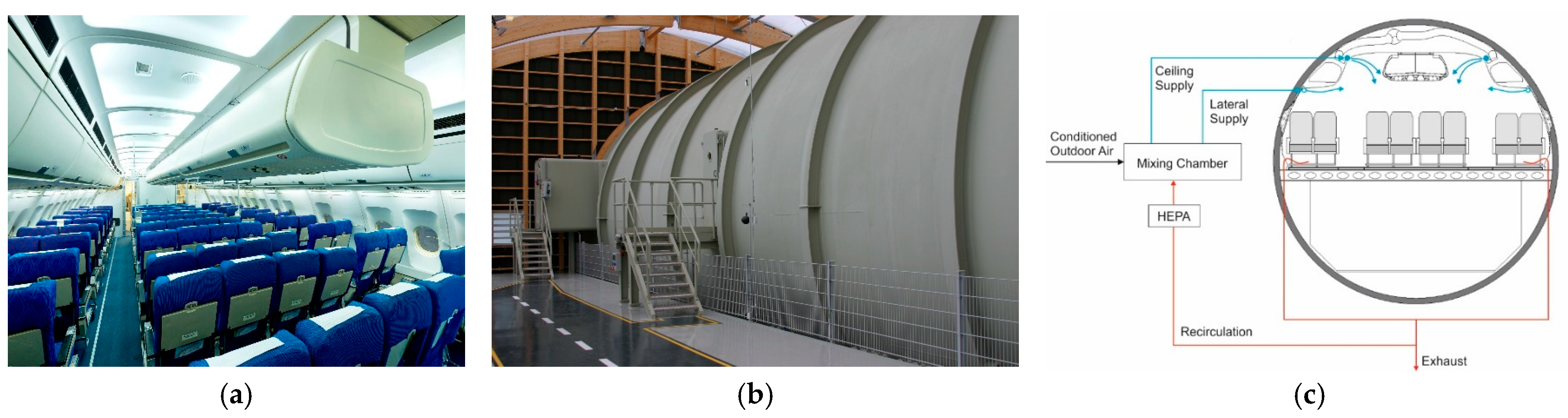
The Fraunhofer Flight Test Facility houses a full-scale front fuselage mockup of a wide-body aircraft (Figure 1a). It includes the cockpit, FWD cabin with galley, avionics bay, FWD cargo hold and FWD bilge. The mockup is integrated in a low-pressure chamber where the pressure envelope of an entire flight can be emulated to generate a realistic takeoff, cruise and descent cabin pressure profile (Figure 1b). To control the outer skin temperature of the mockup, a cladding is built around the mockup. Hot or cold air is circulated between this cladding and the aircraft mockup skin to emulate the desired warm or cold exterior conditions, such as a hot day on the ground or cold temperatures in flight. The mockup also has a realistic ventilation system. Air enters from the ceiling, flows through the cabin, moves into the triangular areas where some air is recirculated, and the rest flows into the bilge and from there is exhausted through the overboard vent (Figure 1c) [7].

2.2. Ventilation Network Modifications

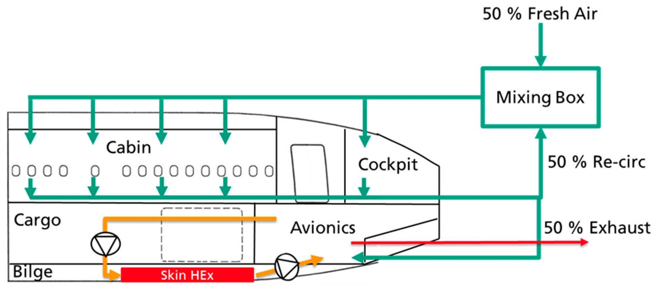
In conventional aircraft, a fraction of the exhaust air from the cabin is diverted to the mixing chamber, and the remaining fraction is diverted to the outflow valve. Within the ORCHESTRA project, this pattern was modified to route roughly 50% of cabin exhaust air through the avionics bay before being diverted to exhaust through the outflow valve. This diverted airflow absorbs the thermal load generated within the avionics bay. A fraction of the ventilation air from the avionics bay is circulated through the skin heat exchanger. This modification allows a higher amount of heat to be dissipated through the skin heat exchanger. As illustrated in Figure 2, an electrically driven extraction fan extracts air from the avionics bay and directs it to the skin heat exchanger, while another electrically driven fan draws air from the skin heat exchanger and supplies it back to the avionics bay.

2.3. Thermal Loads

For the full-scale test, 3.1 kW is assigned to avionics, 7.5 kW to the dual active bridge and up to 10 kW to the AC/DC converter. To emulate these heat loads, four heaters with a combined maximum output of 21.5 kW are installed in the avionics bay. However, to prevent the heaters from switching off due to thermostat control, the operational output of each heater was set to a slightly lower level. The heat output of each heater is shown in Table 1.

2.4. Heat Sink: Skin Heat Exchanger

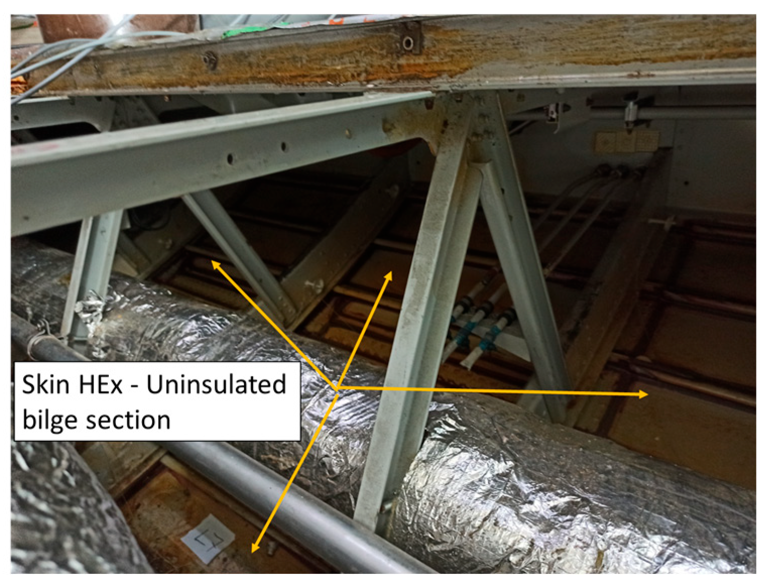
To emulate the skin heat exchanger, approximately 12 m2 of uninsulated bilge area is exposed to the recirculation air from the avionics bay. This uninsulated bilge section, representing the skin heat exchanger, is shown in Figure 3. Recirculation air from the avionics bay is directed to the skin heat exchanger through a recirculation duct by an extraction fan. The target recirculation rate of 170 L/s is then supplied back to the avionics bay by another extraction fan, which draws air from the skin heat exchanger and returns it to the avionics bay.

2.5. In-Flight Operation Test

In-flight operation test boundary conditions are detailed in Table 2. During the in-flight operation test, the cabin ventilation, cabin heat load and exterior environment control were activated simultaneously. However, the avionics heat load and recirculation extraction fans were switched on only after the exterior environment reached the cruise-condition temperature of −25 °C.

2.6. Convective Heat Transfer Meter

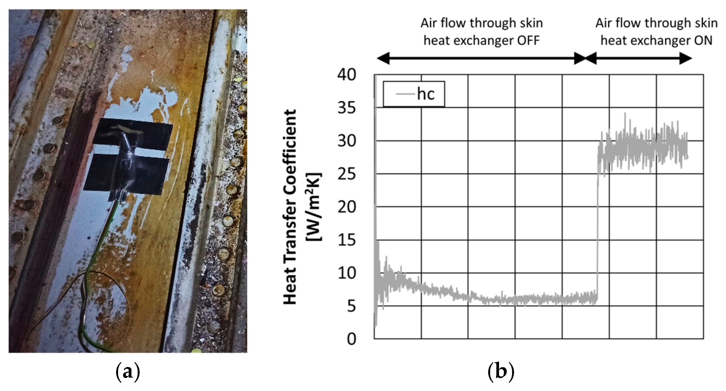
To assess the heat transfer on the skin heat exchanger, a dedicated sensor developed by Fraunhofer, the Convective Heat Transfer Meter (CHM), was used [8]. The sensor measures the temperature difference between the surface and 2 mm into the airflow (within the airflow boundary layer) and 2 cm into the airflow (close to infinite in terms of boundary layer). As the Prandtl number of air (0.7) is close to 1, the thermal and mechanical boundary layers are similar. Hence, the zero velocity condition for flow at the surface translates into a conduction-only condition for the thermal part. Assuming an exponential decline in temperature (and increase in velocity) within the boundary layer, this allows for calculation of the boundary-layer thickness δ and, thus, the convective heat transfer coefficient using the air thermal conductivity λ (Equation (1)). The theoretical framework, including the derivation of the relationship h c λ / δ from boundary-layer theory and its applicability to locally developed wall-bounded flows, is described in detail in [9]. There, the connection between the thermal boundary-layer thickness, wall shear stress and flow regime (laminar and turbulent) is established. The measurement principle of the CHM sensor is described in detail in European Patent [Patent EP 3 446 087 B1] [10].
h c = λ δ
Figure 4 shows the sensor fixed on the skin heat exchanger (Figure 4a) and the measurement result (Figure 4b). It is obvious that when there is no forced airflow in the bilge, the measurement with around 6 W/m2K is close to typical natural convection magnitude. When the airflow cycle of cooling avionics air in the bilge (through skin heat exchanger) is activated, this increased flow translates into an average convective heat transfer coefficient of around 28 W/m2K.

3. Model Validation

The aircraft-level zonal thermal model consists of four domains, cockpit, cabin, underfloor and bulkhead, and was developed to be validated against the experimental data. Each domain is further discretized into multiple zones. The aircraft domains and zonal discretization grid points are shown in Figure 5a [11].
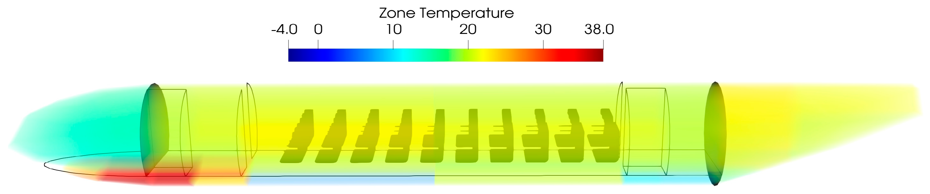
Cabin and cockpit ventilation air is supplied to the zones at ceiling level on both the left and right sides. The overflowing ventilation air is extracted from the zones at floor level (left and right). Fifty percent of the ventilation air extracted from the cabin is diverted to the mixing chamber, and the remaining fraction is diverted to the avionics zone. Avionics heat loads are connected to the respective zones in the avionics volume. The modeled skin heat exchanger, with an area of 12 m2, is shown in Figure 5b. Warm air from the avionics volume is extracted and routed to the skin heat exchanger, where it transfers heat to the exterior environment. This relatively cooler air is then supplied back to the avionics volume. This avionics air recirculation process is shown in Figure 5c. To validate the aircraft-level zonal thermal model, thermal tests were simulated and compared with experimental results. Simulation boundary conditions were derived directly from measurement data. Derived boundary variables include fuselage skin temperature, mockup ventilation inlet flow rate and temperature, heater power in the avionics bay and the convective heat transfer coefficient of the skin heat exchanger. Figure 6 shows a simulated 3D temperature plot of the entire aircraft. The cabin temperature ranges between 22 °C and 23 °C. The cockpit is relatively cooler at around 15 °C. The avionics bay temperature ranges between 20 °C and 38 °C. Forward avionics volumes are cooler than the mid-bay region due to the supply of cooler recirculation air through the skin heat exchanger in the forward avionics bay.
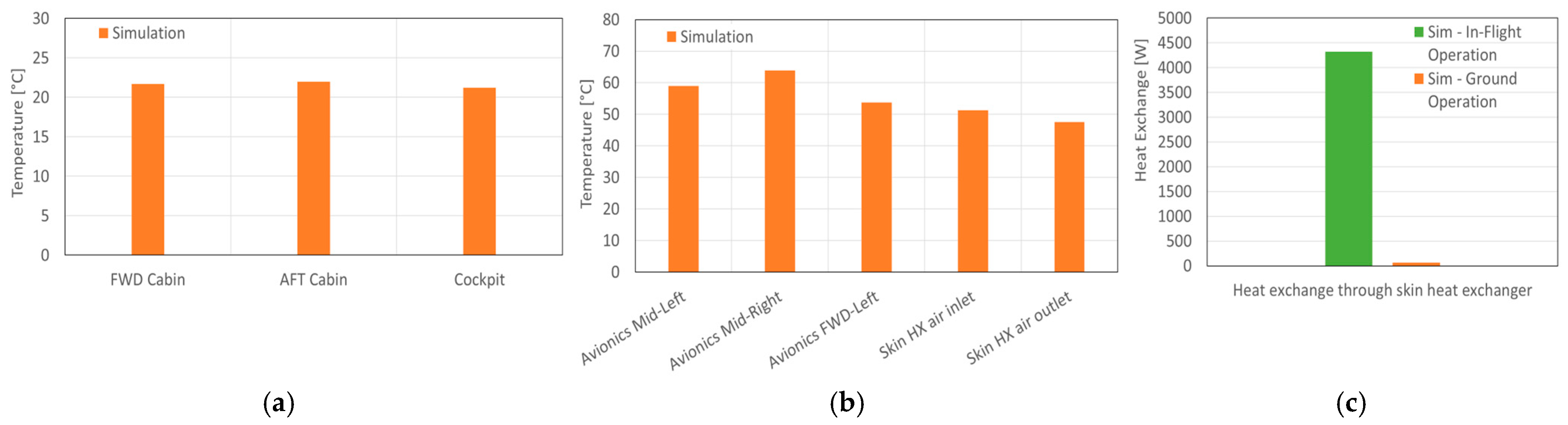
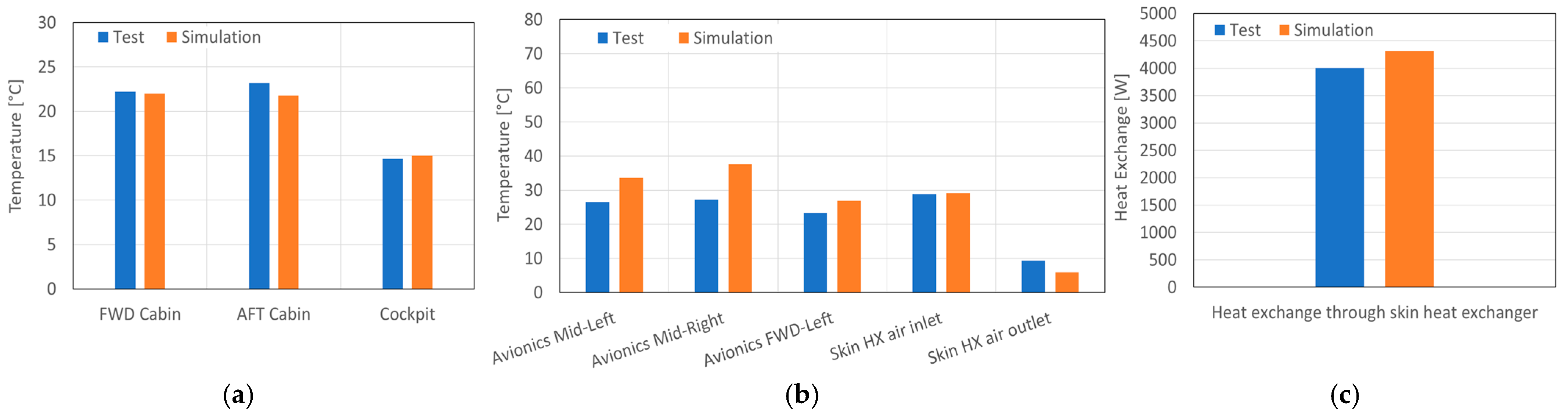
The measured and simulated mean temperatures of the FWD and AFT cabin, as well as the cockpit, are compared in Figure 7a. The absolute deviations for the FWD cabin, AFT cabin and cockpit are 0.2 K, 1.3 K and 0.4 K, respectively.
The measured and simulated mean air temperatures of the avionics bay and the recirculation air are compared in Figure 7b. The absolute deviations for avionics air temperature at Mid-Left, Mid-Right and FWD-Left are 7 K, 10 K and 3 K, respectively. In the test, heat is supplied through electrical heater ventilators, which enhance air mixing within the avionics bay. However, in the simulation model, heat is supplied to the respective zone as a nodal heat load, which results in a comparatively higher temperature gradient. Figure 7c shows a comparison of simulated heat exchange through the skin heat exchanger with the measurements. The measured heat exchange was calculated from the measured recirculation airflow rate, temperatures and convective heat transfer coefficient.

4. Virtual Demonstration of Ground Operation

During ground operation, the benefit of heat dissipation through the skin heat exchanger is limited due to a smaller temperature difference between the interior and exterior of the aircraft. Therefore, additional ventilation air is supplied to the avionics bay. For the ground operation virtual demonstration, the avionics bay is connected to a ventilation source supplying 223 L/s of air at 40 °C (hot day on ground). A ground operation virtual demonstration was performed using the aircraft-level thermal model. The simulation boundary conditions are listed in Table 3.
Figure 8a,b show the simulated mean air temperatures of the FWD and AFT cabin, cockpit and avionics, as well as recirculation air. Figure 8c compares the simulated heat exchange through the skin heat exchanger during in-flight and ground operations. As expected, heat exchange through the skin heat exchanger during ground operation is negligible (66 W). Therefore, additional avionics cooling air is required to dissipate avionics heat when the aircraft is on the ground.

5. Avionics Heat Reuse for FWD Cargo Heating

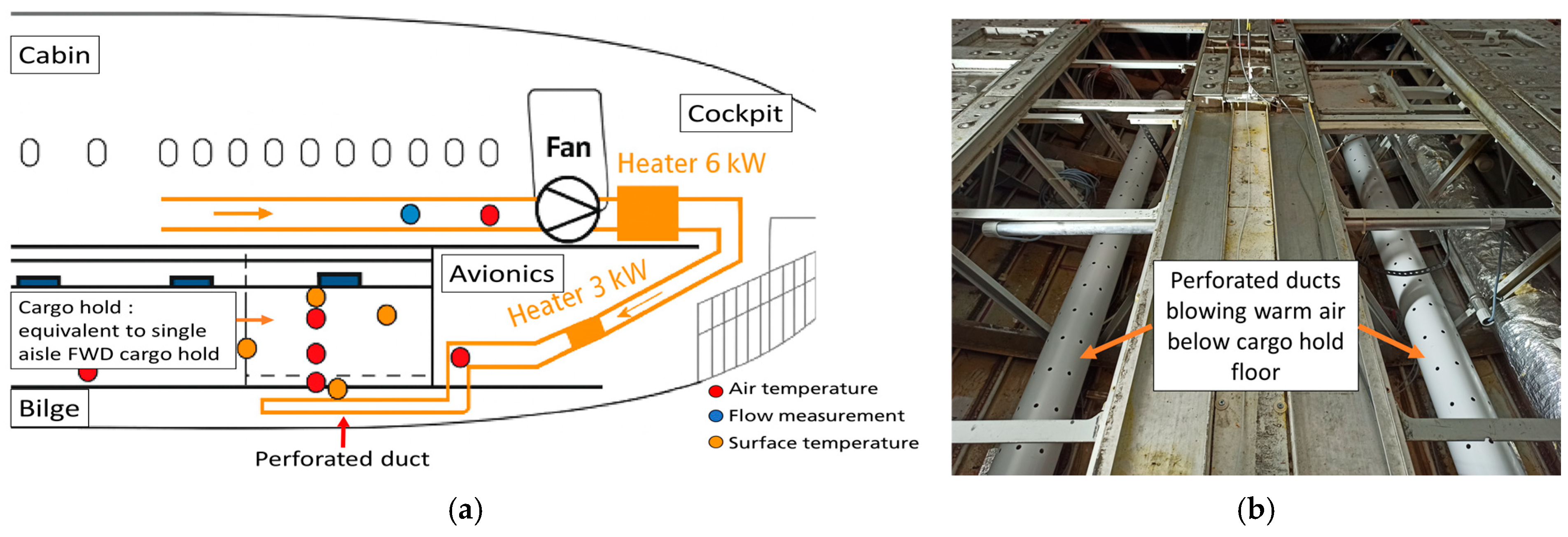
Within the scope of the TheMa4HERA project, it is being investigated how avionics heat could be reused to warm the FWD cargo hold during cold ambient operations. The underlying idea is that thermal energy generated by power electronics and avionics can serve as a secondary energy source, reducing electrical demand on the Environmental Control System (ECS). To test this concept, the system is currently being evaluated at the Fraunhofer Flight Test Facility. The concept uses adaptive airflow routing, as shown in Figure 9a. Air extracted from the cabin passes through 6 kW and 3 kW heat loads emulating avionics heat. The warmed air is then directed to the bilge through ducting, where it is blown beneath the FWD cargo hold floor using perforated ducts (Figure 9b). The perforations face the cargo floor to enhance the convective heat transfer coefficient. Measurements include the temperature of air extracted through the avionics heat loads, air and surface temperatures in the FWD cargo hold, bilge temperature, cargo floor temperature and convective heat transfer coefficients on the cargo floor surfaces (toward both the bilge and cargo hold). This setup will be used to assess the potential for reusing heat to warm the FWD cargo hold.

6. Conclusions

The integration and testing of the demonstrator at the Fraunhofer Flight Test Facility have successfully validated the thermal management concepts developed within the ORCHESTRA project. The resulting aircraft-level thermal model now provides a reliable platform for assessing thermal management strategies across all flight phases, supporting system-level design decisions and enabling flexible virtual analysis of varied operational scenarios. Within the TheMa4HERA project, ongoing experiments will investigate the feasibility of routing avionics heat beneath the cargo hold to support cargo hold heating. The collected data are currently being evaluated, and the system’s overall effectiveness will be assessed based on these experimental results.

Author Contributions

Conceptualization, A.P. and M.P.; methodology, V.N.; validation, A.P., formal analysis, A.P. and M.P.; investigation, A.P.; data curation, M.P.; writing original draft preparation, A.P.; project administration, V.N.; funding acquisition, V.N. All authors have read and agreed to the published version of the manuscript.

Funding

This research was funded by HORIZON-JU-Clean-Aviation-2022-01 Project TheMa4HERA (Grant Agreement number 101102008) and ORCHESTRA (Grant Agreement number: 101006771).

Institutional Review Board Statement

Not applicable.

Informed Consent Statement

Not applicable.

Data Availability Statement

Data can be made available upon request.

Acknowledgments

We would like to thank Maximilian Kienberger from Fraunhofer for setting up the test hardware.

Conflicts of Interest

The authors have no conflicts of interest.

Abbreviations

ECSEnvironment Control System
CHMConvection Heat Transfer Meter
HExHeat Exchanger

References

  1. Buticchi, G.; Wheeler, P.; Boroyevich, D. The More-Electric Aircraft and Beyond. Proc. IEEE 2023, 111, 356–370. [Google Scholar] [CrossRef] [Scilit]
  2. Kuhn, H.; Seitz, A.; Lorenz, L.; Isikveren, A.T.; Sizmann, A. Progress and Perspectives of Electric Air Transport. In Proceedings of the 28th International Congress of the Aeronautical Sciences (ICAS 2012), Brisbane, Australia, 23–28 September 2012. [Google Scholar]
  3. Coutinho, M.; Bento, D.; Souza, A.; Cruz, R.; Afonso, F.; Lau, F.; Suleman, A.; Barbosa, F.R.; Gandolfi, R.; Junior, W.A.; et al. A review on the recent developments in thermal management systems for hybrid-electric aircraft. Appl. Therm. Eng. 2023, 227, 120427. [Google Scholar] [CrossRef] [Scilit]
  4. ORCHESTRA. Available online: https://orchestra-aero.eu/ (accessed on 18 March 2024).
  5. ORCHESTRA Project Optimised Electric Network Architectures & Systems for More Electric Aircraft. Available online: https://orchestra-aero.eu/wp-content/uploads/2024/07/ORCHESTRA-FIA-2024-final.pdf (accessed on 13 May 2026).
  6. Thermal Management for the Hybrid Electric Regional Aircraft. Available online: https://www.clean-aviation.eu/research-and-innovation/clean-aviation/clean-aviation-projects/thema4hera (accessed on 18 September 2024).
  7. Flight Test Facility—The Fraunhofer IBP Flight Lab. Available online: https://www.ibp.fraunhofer.de/en/expertise/energy-efficiency-and-indoor-climate/vehicle-climate-control-systems/flightlab-flight-test-facility.html (accessed on 8 March 2026).
  8. Mayer, E.; Zegowitz, A.; Kersken, M. Messung des konvektiven Wärmeübergangs—Entwicklung eines neuen Sensors und bauphysikalische Anwendungen. Bauphysik 2018, 40, 336–343. [Google Scholar] [CrossRef] [Scilit]
  9. Mayer, E.; Norrefeldt, V. Neudefinition und Messung der Grenzschichtdicke an einer angeströmten Fläche Ermittlung thermodynamischer und aerodynamischer Größen hieraus. Bauphysik 2023, 45, 96–106. [Google Scholar] [CrossRef] [Scilit]
  10. Mayer, E.; Visser, M. Vorrichtung und Verfahren zur Bestimmung des Konvektiven Wärmeübergangskoeffizienten. EP3446087 (B1), 28 October 2020. [Google Scholar]
  11. Matheis, C.; Norrefeldt, V. Heat and species map prediction for the generic MEA using an air node model derived from high level requirements. J. Phys. Conf. Ser. 2023, 2526, 012059. [Google Scholar] [CrossRef] [Scilit]
Figure 1. Flight Test Facility, wide-body mockup (a), low-pressure chamber (b) and schematic representation of cabin ventilation (c).
Engproc 133 00143 g001
Figure 2. Ventilation and bilge airflow network. Schematic representation of the modified airflow network.
Engproc 133 00143 g002
Figure 3. Bilge skin heat exchanger.
Engproc 133 00143 g003
Figure 4. Skin heat exchanger convective heat measurement sensor (a) and measurement (b).
Engproc 133 00143 g004
Figure 5. Aircraft zonal thermal model domains (a), modeled skin heat exchanger (b) and avionics recirculation airflow (c).
Engproc 133 00143 g005
Figure 6. Aircraft zonal thermal model—thermal mapping of simulated results.
Engproc 133 00143 g006
Figure 7. Comparison of simulation with measurement: cabin-cockpit temperatures (a), avionics and heat exchanger inlet/outlet air temperature (b) and heat exchange through skin heat exchanger (c).
Engproc 133 00143 g007
Figure 8. Simulated temperatures of cabin and cockpit (a) and avionics (b), and comparison of simulated heat exchange through skin heat exchanger for in-flight operation with ground operation (c).
Engproc 133 00143 g008
Figure 9. Schematic representation of the avionics heat reuse concept (a), and installed perforated ducts in the bilge (b).
Engproc 133 00143 g009
Table 1. Heaters installed in the avionics bay.
Heater IDMax Power Output [W]Operating Power During Test [W]
H120001830
H220001830
H32000980
H415,50015,030
Table 2. In-flight operation—test boundary condition.
Fuselage Exterior Temp [°C]Cabin Ventilation [L/s]Recirc [%]Skin HX Recirc Rate [L/s]Exhaust—Extraction Rate [L/s]Avionics Heat Load [kW]
−254145017020719.4
Table 3. Ground operation—simulation boundary conditions.
Fuselage Exterior Temperature [°C]Cabin Ventilation [L/s]Recirc [%]Skin HX Recirc Rate [L/s]Ground Ventilation Rate [L/s]Exhaust Extraction Rate [L/s]Avionics Heat Load [kW]
404145017022343019.4
Disclaimer/Publisher’s Note: The statements, opinions and data contained in all publications are solely those of the individual author(s) and contributor(s) and not of MDPI and/or the editor(s). MDPI and/or the editor(s) disclaim responsibility for any injury to people or property resulting from any ideas, methods, instructions or products referred to in the content.