Design of a 150-Seat, 2000 km-Range LH-Fuelled Jetliner †
Abstract
1. Introduction
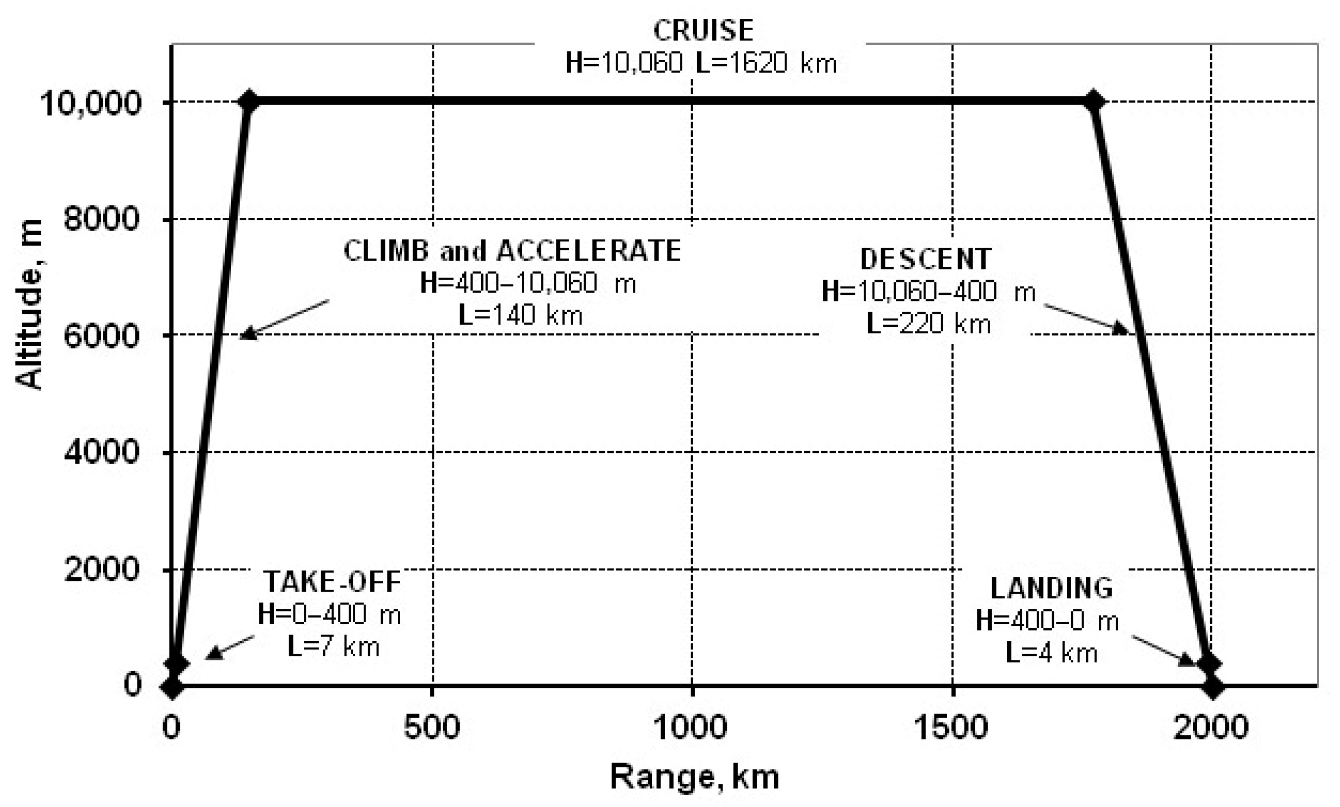
2. Requirements for Aircraft
3. Preliminary Design of a Passenger Aircraft with Hydrogen-Fuelled Propulsion System
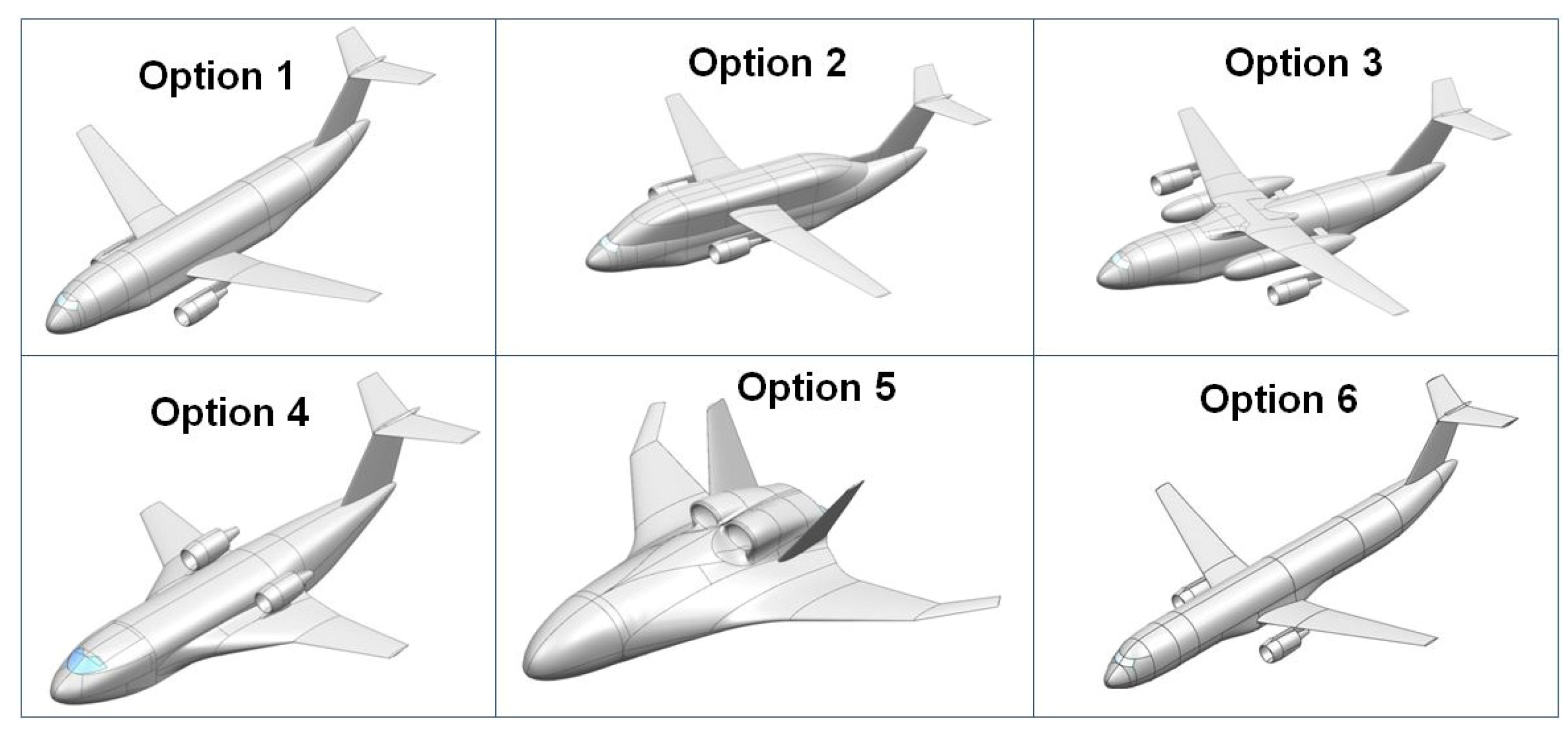
3.1. Aircraft Configuration
3.2. Comparative Assessment of the Options
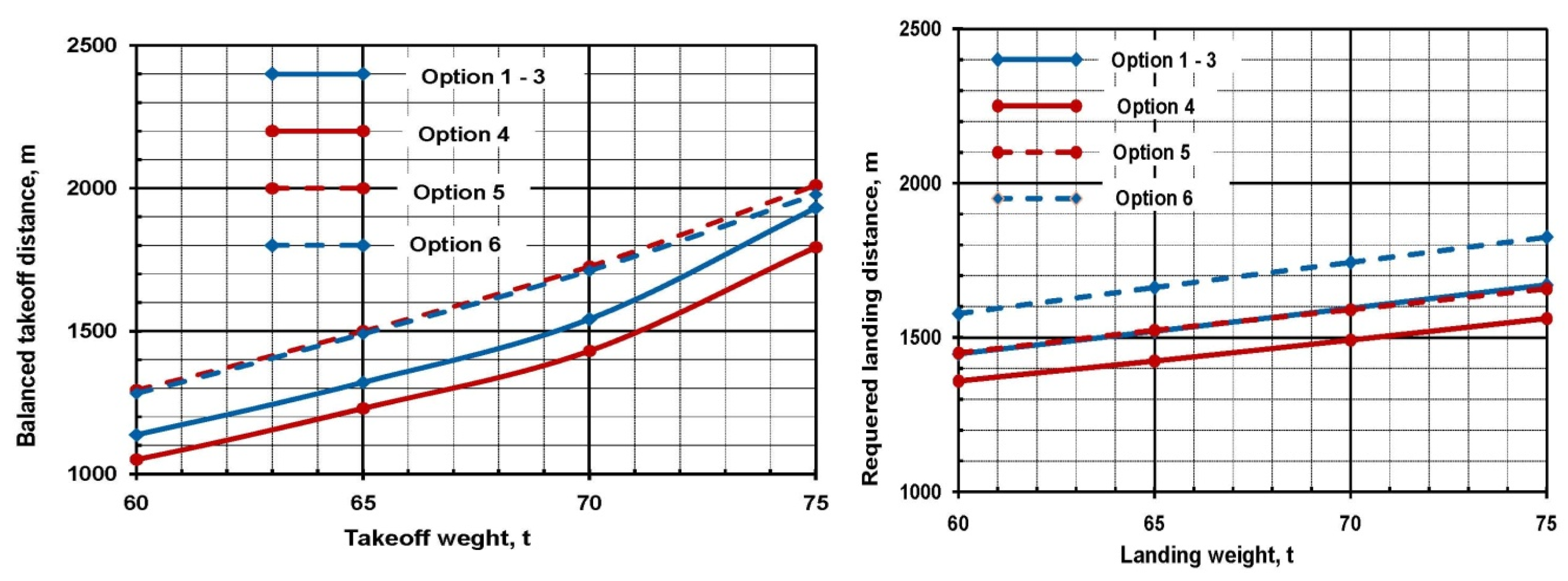
3.3. Take-Off and Landing Performance Comparison
3.4. Quantitative Comparison of Layout Options
3.5. Best Option Selection
- The extended fuselage limits the pitch angle at take-off, which increases the requirements for wing mechanisation;
- Placement of the fuel tanks far behind the centre of gravity (CG) of an empty aircraft leads to a significant expansion of the range of operational alignment, which, in turn, requires an increase in the area of the horizontal plumage;
- The large size of the fuel tank creates obvious difficulties in its maintenance and replacement. For this reason, for Option 6, the trailing edge mechanisation is in the form of a double-slotted Fowler flap (in addition to the full-wing span wing flap). This mechanisation option ensures that the aircraft breaks away on take-off with a pitch angle of only 6.9°. In this case, the breakaway speed VLOF = 262 km/h, CL = 1.64.
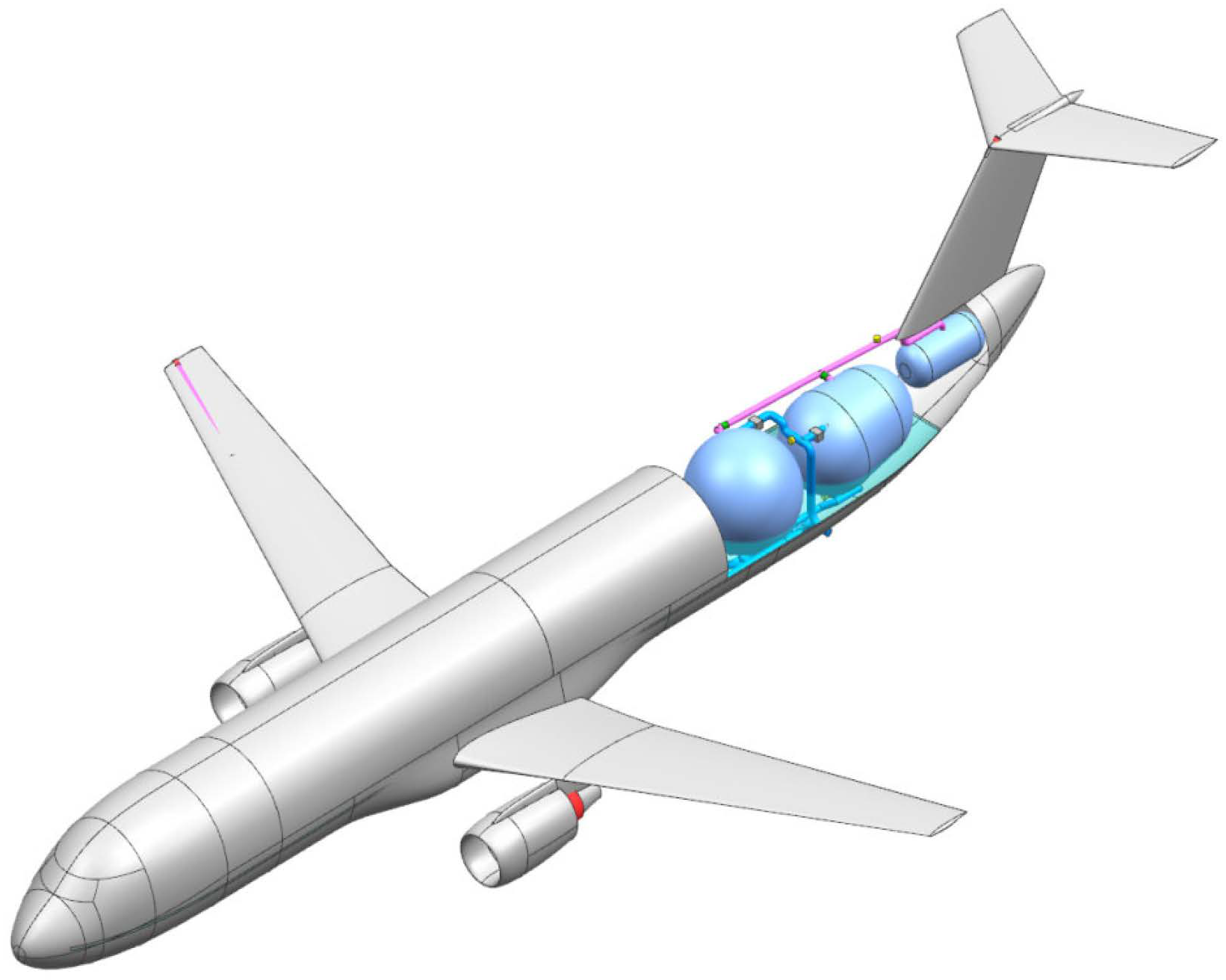
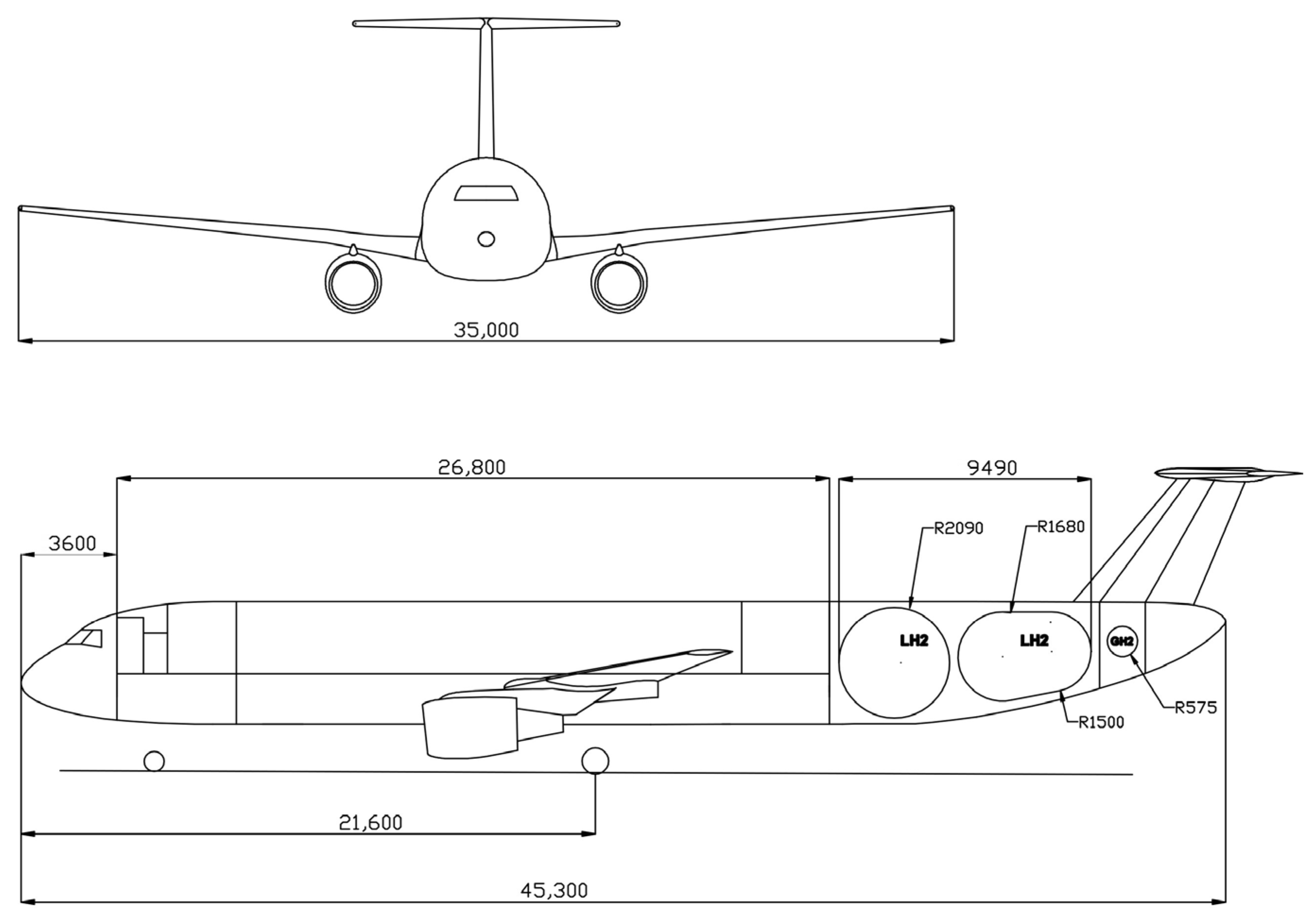
- The three-dimensional visualisation of the Option 6 aircraft are shown in Figure 4.
- The main geometric characteristics of the Option 6 aircraft are shown in Figure 5.
4. Conclusions
Author Contributions
Funding
Institutional Review Board Statement
Informed Consent Statement
Data Availability Statement
Conflicts of Interest
Abbreviations
| CG | Centre of gravity |
| OEW | Operating Empty Weight |
| MTOW | Maximum Take-Off Weight |
| FC | Fuel Cell |
| TOFL | Take-Off Field Length |
| LFL | Landing Field Length |
| LH | Liquid Hydrogen |
| VLOF | Lift-off Speed |
References
- International Air Transport Association (IATA). Aircraft Technology Net Zero Roadmap. 2023. Available online: https://www.iata.org/contentassets/8d19e716636a47c184e7221c77563c93/aircraft-technology-net-zero-roadmap.pdf (accessed on 30 November 2025).
- Flightpath 2050. Europe’s Vision for Aviation: Maintaining Global Leadership and Serving Society’s Needs; European Commission: Brussels, Belgium, 2011; ISBN 978-92-79-19724-6. Available online: https://www.arcs.aero/sites/default/files/downloads/Bericht_Flightpath_2050.pdf (accessed on 30 November 2025).
- Gudmundsson, S. General Aviation Design: Applied Methods and Procedures; Elsevier: Amsterdam, The Netherlands, 2014. [Google Scholar]
- Simanullang, M. Liquid Hydrogen Storage and Insulation Materials for Liquid Hydrogen Storage Tanks: Trends and Challenges. Int. J. Hydrogen Energy 2025, 50, 881–888. [Google Scholar] [CrossRef] [Scilit]
- Naquash, A.; Agarwal, N.; Lee, M. A Review on Liquid Hydrogen Storage: Current Status, Challenges and Future Directions. Sustainability 2024, 16, 8270. [Google Scholar] [CrossRef] [Scilit]
- Monkam, L.K.; von Schweinitz, A.G.; Friedrichs, J.; Gao, X. Feasibility Analysis of a New Thermal Insulation Concept of Cryogenic Fuel Tanks for Hydrogen Fuel Cell Powered Commercial Aircraft. Int. J. Hydrog. Energy 2022, 47, 31395–31408. [Google Scholar] [CrossRef] [Scilit]
- Brewer, G.D. Hydrogen Aircraft Technology; CRC Press: Boca Raton, FL, USA, 1991. [Google Scholar]
- Raymer, D.P. Aircraft Design: A Conceptual Approach, 6th ed.; AIAA: Reston, VA, USA, 2018. [Google Scholar]
- Airbus. A220-300 (CS300) Specifications. Available online: https://www.airbus.com/en/products-services/commercial-aircraft/passenger-aircraft/a220-family (accessed on 11 May 2026).
- Airbus. A320 Family Specifications. Available online: https://www.airbus.com/en/products-services/commercial-aircraft/passenger-aircraft/a320-family (accessed on 11 May 2026).



| Maximum series production rate of aircraft | ≥30 units per year |
| Estimated total production | ≥300 units |
| Estimated catalogue value of a production aircraft | 120 million USD |
| Number of passengers | ≥150 |
| Maximum commercial load | 18 t |
| Maximum flight altitude | 12,000 m; |
| Estimated weight of a passenger with baggage | 105 kg; |
| Design cruising speed | 820 km/h |
| Design range | 2000 km |
| Type certificate | CS 25 (FAR-25) |
| Noise in the passenger cabin | ≤75 dBA |
| Certified flight altitude | ≤12,000 m (40,000 ft) |
| Airfields of operation | Code ≥ 3C |
| After-sales support | 24/7, all year round |
| Service life | ≥30 years |
| Option 1 | Option 2 |
 |  |
Advantages:
| Advantages:
|
Disadvantages:
| Disadvantages:
|
Aerodynamic considerations:
| Aerodynamic considerations:
|
| Option 3 | Option 4 |
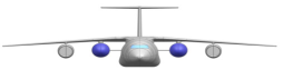 |  |
Advantages:
| Advantages:
|
Disadvantages:
| Disadvantages:
|
Aerodynamic considerations:
| Aerodynamic considerations:
|
| Option 5 | Option 6 |
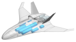 |  |
Advantages:
| Advantages:
|
Disadvantages:
| Disadvantages:
|
Aerodynamic considerations:
| Aerodynamic considerations:
|
| Option | 1 | 2 | 3 | 4 | 5 | 6 |
|---|---|---|---|---|---|---|
| MTOW, t | 72.2 | 73.0 | 73.4 | 75.2 | 73.0 | 73.4 |
| Wing area, m2 | 135 | 135 | 135 | 200 | 200 | 135 |
| Cl max | 2.4 | 2.4 | 2.4 | 1.5 | 0.9 | 2.4 |
| TOFL, m | 1700 | 1780 | 1800 | 1830 | 1900 | 1920 (1820 2-sl. F. flap) |
| LFL, m | 1600 | 1610 | 1620 | 1530 | 1600 | 1770 |
| Quality Factor | Integral Index (Quality Factor) | ||||||||
|---|---|---|---|---|---|---|---|---|---|
| Cost of Aircraft, M$ | Fuel Efficiency, MJ/p-km | Safety | Possibility of Developing | ||||||
| Weight Factor | 0.30 | 0.30 | 0.30 | 0.10 | |||||
| abs. | norm. | abs. | norm. | abs. | norm | abs. | norm. | ||
| Option 1 | 117.5 | 1 | 0.936 | 1 | 0.6 | 0.60 | 0.9 | 0.90 | 0.863 |
| Option 2 | 117.7 | 0.98 | 1.056 | 0.87 | 0.7 | 0.70 | 0.9 | 0.90 | 0.854 |
| Option 3 | 118.2 | 0.97 | 1.145 | 0.78 | 0.8 | 1 | 0.9 | 0.90 | 0.855 |
| Option 4 | 126.1 | 0.90 | 1.132 | 0.79 | 0.6 | 0.60 | 1 | 1 | 0.788 |
| Option 5 | 126.0 | 0.90 | 1.089 | 0.84 | 0.6 | 0.6 | 1 | 1 | 0.802 |
| Option 6 | 115.0 | 1 | 0.95 | 0.99 | 1 | 1 | 0.7 | 0.8 | 0.966 |
| Option 6 | A320 | CS300 | ||
|---|---|---|---|---|
| Engines | -Type -Take-off thrust, tf Cr max. Cruising (M = 0.75, H = 11 km), kg/kgf h | TurbofanPW1431G 2 × 13.3 0.522 (on kerosene) | CFM56-5A (B) 2 × 12.25 0.62 | PW1521G 2 × 9965 0.565 |
| MTOW, t | 73.60 | 77.0 | 67.6 | |
| OEW, t | 53.30 | 43.6 | 38.9 | |
| Maximum Payload, t | 18 | 20.8 | 20.8 | |
| Passenger weight with baggage, t | 15.75 | 16.9 | 16.9 | |
| Additional Payload, t | 2.25 | 3.9 | 1.73 | |
| Maximum fuel weight (LH2 γ = 0.071 kg/dm3; kerosene γ = 0.81 kg/dm3), t | 3.43 (9.35 kerosene) | 18.8 | 18.1 | |
| Wing area, m2 | 135 | 122 | 112 | |
| Wing span, m | 35.0 | 34.0 | 35.1 | |
| Wing aspect ratio | 9.1 | 10.5 | 11.0 | |
| Wing sweep at ¼ chord, deg. | 23 | 25 | 25 | |
| Fuselage cross-section, length x width, m | 4.62 × 4.62 | 4.16 × 3.95 | 3.7 | |
| Fuselage length, m | 45.3 | 37.5 | 38.7 | |
| Number of LH2 fuel tanks | 2 | — | — | |
| Passengers | Single class Two class | 164 150 | 164 150 | 140 132 |
| OEW/seat (two class), kg | 355 | 291 | 295 | |
| Aisle width in economy class, inch (cm) | 20.5 (52) | 19 (48) | 20 | |
| Seat width in economy class, inch (cm) | 18 (46) | 18 (46) | 18 (46) | |
| Cruising altitude, km | 10.6–12.0 | 10.6–12.0 | 10.6–12.0 | |
| Cruising speed, km/h | 820 | 840 | 840 | |
| Fuel efficiency (150 pas.), MJ/p-km | 0.955 | 0.770 | 0.800 | |
| Runway length (ISA, SL), m | For take-off For landing | 1920 (1820 2-sl. F. flap) 1770 | 2200 1530 | 2500 1500 |
Disclaimer/Publisher’s Note: The statements, opinions and data contained in all publications are solely those of the individual author(s) and contributor(s) and not of MDPI and/or the editor(s). MDPI and/or the editor(s) disclaim responsibility for any injury to people or property resulting from any ideas, methods, instructions or products referred to in the content. |
© 2026 by the authors. Licensee MDPI, Basel, Switzerland. This article is an open access article distributed under the terms and conditions of the Creative Commons Attribution (CC BY) license.
Share and Cite
Fil, S.; Berbenets, D.; Khaustov, A.; Urban, O.; Bondarchuk, O. Design of a 150-Seat, 2000 km-Range LH-Fuelled Jetliner. Eng. Proc. 2026, 133, 125. https://doi.org/10.3390/engproc2026133125
Fil S, Berbenets D, Khaustov A, Urban O, Bondarchuk O. Design of a 150-Seat, 2000 km-Range LH-Fuelled Jetliner. Engineering Proceedings. 2026; 133(1):125. https://doi.org/10.3390/engproc2026133125
Chicago/Turabian StyleFil, Serhii, Dmytro Berbenets, Andrii Khaustov, Oleksandra Urban, and Oleksandr Bondarchuk. 2026. "Design of a 150-Seat, 2000 km-Range LH-Fuelled Jetliner" Engineering Proceedings 133, no. 1: 125. https://doi.org/10.3390/engproc2026133125
APA StyleFil, S., Berbenets, D., Khaustov, A., Urban, O., & Bondarchuk, O. (2026). Design of a 150-Seat, 2000 km-Range LH-Fuelled Jetliner. Engineering Proceedings, 133(1), 125. https://doi.org/10.3390/engproc2026133125