1. Introduction
Coaxial cable is widely used in telecommunications, network, and television broadcasting and many other fields, playing a vital role in the transmission of signals. However, in practical applications, the length of the cable and the terminal load condition often affect the quality and transmission efficiency of the signal. Therefore, it is of great practical significance and application value to research and develop a device for effectively measuring coaxial cable length and terminal load [
1,
2,
3]. The significance and purpose of researching this detection device are reflected in the following aspects:
Improving the quality and efficiency of signal transmission. By accurately measuring the cable length and terminal load, the characteristic impedance of the cable and load can be effectively matched, and the signal reflection and loss can be reduced, thus improving the quality and efficiency of signal transmission. This is particularly important for modern communication systems with high data transmission speed requirements.
Promoting the optimal design of networks and systems. Accurate cable and load data can help engineers consider the optimal path and configuration of signal transmission at the design stage, reduce future maintenance costs and system upgrade difficulties, and improve the performance and reliability of the entire network.
Simplifying maintenance and troubleshooting. Quickly and accurately locating cable length and end load issues can significantly reduce maintenance time and costs. This is particularly important for widely deployed communications and broadcast networks that can respond quickly to failures and ensure continuity and reliability of services.
Improving network security. By monitoring changes in cable and load conditions, signs of illegal access or damage to the network can be detected in time, and measures taken to protect the network from interference and to enhance the security of the communication network.
Supporting the provision of high-quality services. For applications that require high signal quality, such as high-definition video transmission, telemedicine, and high-frequency trading, accurate cable and load detection can guarantee high-quality service that meets the high standards of users.
Promoting the development of new technologies and new products. Research and development of efficient cable and load detection technologies can stimulate the innovation of new products and services, and bring new growth points to related industries.
To sum up, research into coaxial cable length and terminal load detection devices is of great significance for improving the performance of communication systems, reducing maintenance costs, providing high-quality service and promoting technological progress. This research can not only improve the performance and reliability of coaxial cable system, but also bring significant economic and social benefits to the communication industry and promote the development of communication technology.
2. Current Situation and Trends in China and Abroad
The research field of coaxial cable length and terminal load detection is an active one, as many research institutions and enterprises at home and abroad have carried out many studies in this regard.
2.1. Domestic Research Status
China’s research into coaxial cable inspection technology mainly focuses on two aspects of technological innovation and practical application, including improving traditional cable testing methods, such as the optimization of TDR (time domain reflectometer) technology, and developing cable inspection devices based on new sensors and signal processing algorithms. With the rapid development of the communications industry, more attention is being paid to the standardization of industry standards and test methods to ensure the quality and compatibility of cable products and testing technologies. Research into cable inspection technology involves many fields such as materials science, electronic engineering, computer science, etc. Domestic researchers have made certain progress in promoting interdisciplinary cooperation and the innovation and application of inspection technology [
4,
5].
2.2. Status of International Research
Internationally, research into cable length and load detection technology focuses more on high-precision measurement and automated operation; for example, the use of high-precision time measurement equipment and automated data processing software to improve the accuracy and efficiency of detection. International researchers have made remarkable achievements in non-destructive testing and remote monitoring technologies which can monitor the status of cables and loads in real time without interfering with normal communication, which is of great significance for improving network reliability and reducing maintenance costs. With the development of artificial intelligence and Internet of Things technology, international research is increasingly focused on applying intelligent algorithms and network management to cable inspection to achieve more efficient and intelligent cable management and fault prediction [
6].
2.3. Research Trends
Both in China and abroad, future research will continue to pursue higher measurement accuracy and faster detection speed to meet growing communication needs. Emerging technologies, such as big data, cloud computing, artificial intelligence, etc., will be further integrated into cable inspection technology to improve the level of intelligence and automation of detection. Future research will pay more attention to user experience and environmental impact, and develop more humane and environmentally friendly cable inspection solutions. With increasing threats such as cyber attacks and natural disasters, future research will focus more on improving the security and reliability of cable networks.
Overall, research on coaxial cable length and terminal load detection technology will continue to deepen, not only to improve the performance of the technology itself, but also to include its broad applications, the standardization process, and the integration of emerging technologies.
3. Scheme Design
3.1. Coaxial Cable Length Test Scheme
The capacitance method is used to measure the coaxial cable length. The distance between the twisted lines inside the coaxial cable is exactly equal, and the distributed capacitance between the two lines is evenly distributed along the cable. An open coaxial cable is used as a capacitor, where the distance between the twisted lines is equivalent to the dielectric of the capacitor, and the twisted lines themselves are equivalent to the two plates of the capacitor. An RC oscillating circuit is used to generate a sine wave signal with a certain linear relationship to the length of the coaxial cable. The frequency of this RC oscillator circuit is proportional to the length of the cable [
7]. Then, the length of the coaxial cable can be indirectly determined by measuring the frequency of the sinusoidal signal output of the RC oscillator circuit. The method requires no physical intervention with the cable, and the measurement process is simple and non-destructive.
3.2. Resistance Load Detection Scheme
The resistance load is measured by the series partial pressure method. In a series circuit, the individual resistors in the circuit are connected together in order to form a circuit through which the current can flow in only one direction. Since the resistors in the series circuit are on the same current path, according to Ohm’s law, the current remains constant in the series circuit. Therefore, the current across each resistor is equal. According to Kirchhoff’s voltage law, the sum of the voltages at both ends of each resistor in a series circuit is equal to the total voltage of the circuit. Thus, the voltage across each resistor in the circuit is a partial voltage of the total voltage. According to the principle of voltage distribution, if there are two resistors in the circuit, then the voltage ratio between them is equal to their resistance ratio, that is, R1:R2 = U1:U2. This scheme is simple and easy to understand, suitable for voltage distribution in series circuits.
3.3. Capacitive Load Detection Scheme
An RC oscillation circuit is used, a common method used to measure the capacitance value of the cable load. The RC oscillator circuit consists of a resistor (R) and a capacitor (C). In an oscillating circuit, resistors and capacitors form a phase-shifting network, creating a feedback loop that allows the circuit to generate self-excited oscillations. When the RC oscillator circuit reaches a stable state, its output signal is sinusoidal. The oscillation frequency (f) of the RC oscillation circuit is related to the value of the resistance (R) and capacitance (C), the specific calculation formula is f = 1/2πRC, and the frequency of the sine wave signal generated by the RC oscillation circuit is measured by a single-chip microcomputer. According to the measured frequency and the known resistance value, the relationship between the frequency and the RC value is calculated using the above formula. This method is simple, direct and does not require complex measuring equipment.
3.4. Overall Scheme Design
This design uses a DC5V power supply and the buck module LM2596 to reduce the 5 V input voltage to 3 V. At the same time, the booster module XLSEMI XL6009 (XLSEMI, Shanghai, China) increases the input voltage from 5 V to 12 V to supply the required voltage for subsequent modules. STMicroelectronics STM32F407VET6 is selected as the main control chip as the center of the whole system, which is responsible for controlling the relay to switch between the resistance measurement circuit and the HGSEMI ICL8038 oscillation circuit (Huagao Semiconductor Co., Ltd., Wuxi, China). The RC oscillating circuit is used to measure cable length and load capacitance. The load resistance value is measured using the principle of resistance voltage division, and the precise value of resistance is obtained by reducing the voltage of LM2596 to 3 V and using the ADC of STM32F407VET6. Through the design of the above power supply circuit and RC oscillation circuit, the relevant parameters can be accurately measured within the specified time, and the coaxial cable length and terminal load can be measured [
8,
9].
4. Theoretical Analysis and Calculation
Combined with the capacitance method and other measurement techniques, the coaxial cable length and terminal load can be measured. Viewing an open coaxial cable as a capacitor, where the stranded lines are viewed as two plates of a flat capacitor, this perspective allows the length of the cable to be related to the size of the capacitor. When the coaxial cable is in the open state, by measuring its open frequency, it can be observed that there is a function rule between the frequency and the cable length. Generally, the relationship between the cable length and the open frequency is linear, and can be analyzed and modeled using the experimental data. By collecting and analyzing the open circuit frequency data of coaxial cables of different lengths, the linear relationship between frequency and cable length can be obtained. In this way, this relationship can also be used to measure an unknown length of coaxial cable. By measuring the open circuit frequency, it is also possible to determine whether the terminal load of the coaxial cable is capacitance or resistance. Connecting the capacitor to the cable terminal will change the oscillation frequency, while the resistor will not generate the frequency. If resistance is detected, the resistance value can be detected by means of a series voltage division. The proportion of resistance in the series divider circuit is proportional to the terminal resistance of the cable, so the size of the resistance can be determined by measuring the voltage proportion; if capacitance is detected, the RC oscillating circuit can be used to test it. The frequency generated by the RC oscillator circuit is inversely proportional to the value of the capacitor, so the size of the capacitor can be determined by measuring the oscillation frequency. By combining the above steps, it is possible to detect the length of the coaxial cable and the terminal load. This method uses a capacitor, series voltage division and RC oscillation circuit, and provides a comprehensive and effective coaxial cable detection scheme.
5. Core Circuit Design
5.1. RC Oscillator Circuit
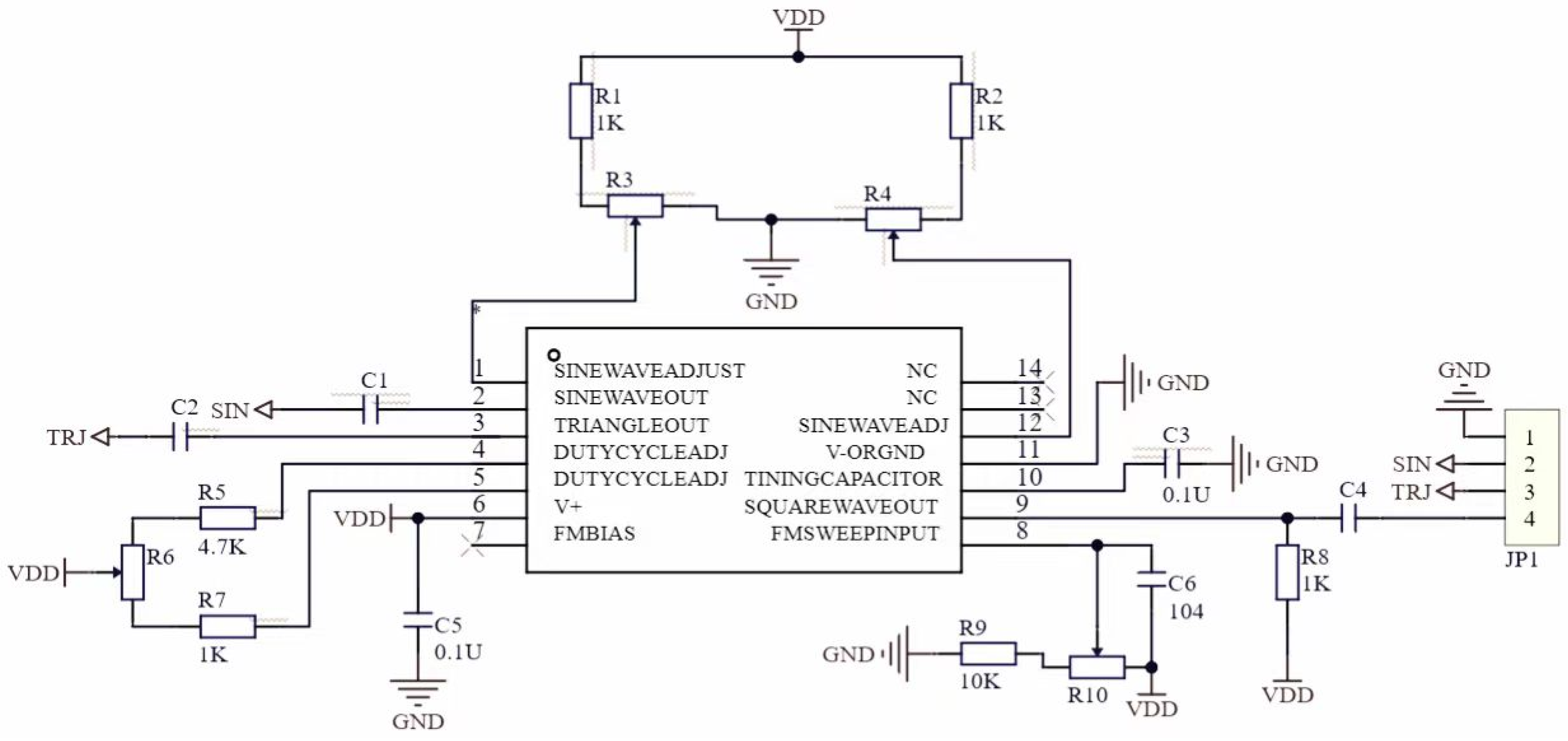
As shown in
Figure 1. ICL8038 is a commonly used integrated circuit waveform generator which can produce different types of waveform output such as sine waves, square waves and triangle waves. Its oscillation frequency (output frequency) is directly related to the size of its Pin10 external capacitor. C3 pin capacitance can be changed directly to change its oscillation frequency, and R5, R6, and R7 can be changed to adjust the current of the constant current source to change the charge and discharge time constants of capacitor C3, thus changing the frequency of the square wave. Among them, the external resistance between Pin 4 and Pin 5 of R5, R6, R7, and C3 is the external capacitance of Pin 10.
Since the TDR effect of the coaxial cable can be equivalent to the capacitance Cap, the external pin resistors Pin 4 and Pin 5 are fixed, and the equivalent capacitance is connected to Pin 10, which causes the output frequency to change. The oscillation frequency is inversely proportional to C3, that is, the larger C3 is, the lower the oscillation frequency is. The smaller the C3, the higher the oscillation frequency. The output frequency is collected by STM32F407, and the cable length and load capacitance are obtained by a series of transformations. The schematic diagram of the circuit is shown below.
5.2. Switching Circuit
The RC oscillator circuit is a capacitor- and resistance-based circuit used to generate periodic signals. Under normal conditions, the RC oscillator circuit will meet the vibration conditions and produce a stable oscillation signal. If the load is resistance, then the impedance in the circuit will change, which may cause the oscillating circuit to fail to meet the vibration conditions, and as a result, it cannot produce an oscillating signal, at which time the measured frequency is 0. When the RC oscillator circuit is detected to be unable to vibrate, this indicates that the current load is resistance. In order to measure resistance, the circuit needs to be switched to a series divider circuit suitable for resistance measurement. The Onsemi LM358 (Onsemi, Scottsdale, AZ, USA) is a common operational amplifier that can be used to build voltage followers. The role of the voltage follower is to output the same voltage as the input signal voltage. It has the characteristics of high input impedance and low output impedance, which can make the input impedance of the circuit high and the output impedance low. In this scenario, the LM358 voltage follower is used to change the output voltage capability of the I/O port of the microcontroller. Generally speaking, the output capacity of the I/O port of a single-chip microcomputer is limited, and it can not directly drive a large load. By connecting the LM358 voltage follower, the I/O port of the microcontroller can control the input of the LM358, while the output of the LM358 can drive a larger load. In summary, it is possible to determine whether the current load is resistance by detecting the starting vibration of the RC oscillator circuit. If it is resistance, switch to a series divider circuit for measurement. The role of the LM358 voltage follower is to change the output capacity of the I/O port of the single-chip microcomputer in order to drive a larger load.
5.3. Software Design
After the main program is started, the start interface and prompt information are displayed, and the output signal of the detection comparator is called to determine whether the key is pressed. If the key is pressed, it is further determined which key is pressed. Press the detection signal frequency, calculate the coaxial cable length corresponding to the frequency, and finally display the coaxial cable length; press button 2 to determine whether there is a signal: if yes, detect the signal frequency, calculate the capacitance corresponding to the frequency, and finally display the capacitance capacity; if no, switch the detection line, detect the voltage of the voltage-dividing circuit, calculate the resistance value corresponding to the voltage, and finally display the resistance value.
The overall program design includes the following steps: 1. Design the main program, including the interface display and prompt information. 2. Write a function to call the detection comparator and output the signal. 3. Write a function to determine whether a key is pressed, and further determine which key is pressed. 4. Write functions to handle the logic when key 1 is pressed, including detecting the signal frequency, calculating the cable length and displaying the result. 5. Write functions to handle the logic when key 2 is pressed, including detecting whether the signal is present, calculating the capacitance, and displaying the result. 6. Write functions to handle the logic when there is no signal, including switching the detection line, detecting the voltage and calculating the resistance value, and finally display the result.
6. Test and Test Results
6.1. Scheme Testing
Debug the hardware system, connect the cable under test (selecting the 15442A coaxial cable as the test object) into the device, press button 1 to test the length of the coaxial cable; and press button 2 to determine whether the RC vibrates. If it vibrates, the load capacitance is detected. If the conditions for starting vibration are not met, check the load resistance.
6.2. Coaxial Cable Length Test
Open the terminal and press the “Length detection” key to start the detection. The device can detect and display the cable length L, where the absolute value of the relative error is not more than 5% and detection time is not more than 5 s.
Table 1 shows the cable length test data:
6.3. Load Judgment Test
After completing the coax cable length detection under the open terminal condition, keep L unchanged. After the terminal accesses any load in the resistor or capacitor, the device can correctly judge and display the load type after starting the load detection, and the detection time does not exceed 5 s. The test results are shown in
Table 2:
6.4. Load Value Test
After the length detection is completed in the open terminal condition, keep L unchanged, and to access a load in the terminal resistance or capacitor, press the “Load detection” key to start the detection. The device detects and displays the resistance and capacitance of the load on the basis of correctly judging the load type. The absolute value of the relative error is less than 10%, and the detection time is less than 5 s. The results are shown in
Table 3 and
Table 4:
7. Conclusions
A coaxial cable length and terminal load detection system based on STM32F407VET6 is designed in this paper, aiming to achieve the accurate detection of coaxial cable length and terminal load type and value. The system mainly includes two parts: hardware circuit design and software program design.
In the hardware circuit, the system uses STM32F407VET6 as the main control chip, and detects coaxial cable length through the function relationship between open frequency and coaxial cable length. By judging the frequency, the system can identify the type of terminal load. If it is a resistor, the resistance value is detected by a series voltage division method; if it is a capacitor, the RC oscillation circuit composed of ICL8038 is used for detection. The designed hardware circuit can display the working state of the system and other indicators to ensure the stable and reliable operation of the system.
In the software program design, STM32 control is used to quickly detect coaxial cable length and terminal load. The program can accurately calculate the length of the cable according to the function relationship between the open frequency and the cable length, and display it on the interface. At the same time, the program can identify the type of terminal load, detect the resistance or capacitance value according to the specific situation, and display it on the interface.
The system test results show that the device can work stably and reliably. When the cable length is 1000 cm ≤ L ≤ 2000 cm and the terminal is open, the device can quickly and accurately detect and display the cable length L, the absolute value of the relative error is not greater than 1%, and the detection time is not more than 5 s. At the same time, it can correctly judge and display the load type, and on the basis of correctly judging the load type, detect and display the resistance or capacitance value of the load, where the absolute value of the relative error is not more than 5%, and the detection time is not more than 5 s.
The coaxial cable length and terminal load detection system designed in this paper has good performance and stability, can meet practical application requirements, and has certain engineering practical value. In future, the function and performance of the system can be further optimized, and its application in the field of coaxial cables can be expanded.
Author Contributions
C.Y.: conceptualization, methodology design, software development, system validation, formal analysis, investigation, resource coordination, data curation, manuscript writing (original draft), visualization, project supervision, and management. W.H.: validation of the coaxial cable length and terminal load monitoring system (including hardware debugging and test data verification), and review and editing of the manuscript. S.Y.: experimental validation of the coaxial cable length and terminal load monitoring system (focusing on the performance analysis of the RC oscillation circuit and the verification of load detection accuracy), and review and editing of the manuscript. All authors have read and agreed to the published version of the manuscript.
Funding
This work was financially supported by the Science and Technology Research Project of the Science and Technology Bureau of Bishan District, Chongqing (BSKJ2022002), and the Science and Technology Research Project of Chongqing Education Commission (KJQN202203702).
Institutional Review Board Statement
Not applicable.
Informed Consent Statement
Not applicable.
Data Availability Statement
The data that support the findings of this study are available from the corresponding author upon reasonable request.
Acknowledgments
Thanks to Chongqing Vocational and Technical University of Mechatronics for providing administrative and technical support, including experimental sites, the use of equipment (such as STM32F407VET6 development boards and ICL8038 integrated circuits), and academic exchange platforms; thanks to Chongqing University of Science and Technology for providing technical collaboration support. Thanks to the relevant personnel who assisted in the experimental validation and data collection process, especially those who participated in the testing of 15442A coaxial cables, the recording of test results, and data verification. Thanks to the researchers who put forward constructive suggestions on the overall scheme design of the monitoring system and the optimization of the experimental process.
Conflicts of Interest
The authors declare no conflicts of interest.
References
- Chen, W.; Wang, Q.; Wu, G.; Li, Y.; Tan, J.; Yan, K.; Tan, K. Research on length measurement Technology of High-voltage Power Cable based on time-domain pulse Reflection. China Instrum. 2020, 83–87. (In Chinese) [Google Scholar]
- Wu, Q. Experimental Device for Innovative Design of Capacitor Characteristics using RC Oscillating Circuit. Field Middle Sch. Sci. Dep. 2020, 16, 52–53. (In Chinese) [Google Scholar]
- Li, Z. Realization and Analysis of Oscillation Circuit. Sci. Technol. Vis. 2014, 83–84. (In Chinese) [Google Scholar]
- Guo, H.; Huang, J.; Zhao, L. An Oscillating Circuit with high Stability. Electron. Packag. 2012, 12, 26–27+34. (In Chinese) [Google Scholar]
- Li, B. Research on Accurate Length Measurement Technology of Wire and Cable Based on Time-Domain Pulse Reflection Principle. Ph.D. Thesis, Xidian University, Xi’an, China, 2010. [Google Scholar]
- Ren, J. Output Amplitude Analysis of RC Bridge Sine Wave Oscillator Circuit. Electron. Des. Eng. 2013, 21, 107–108+110. (In Chinese) [Google Scholar]
- Wei, H.; Shuai, X. Direct Current Circuit Analysis of Time Domain Reflectometry with Variable Coaxial Cable Length for Electrical Conductivity Measurements. Soil Sci. Soc. Am. J. 2019, 83, 324–326. [Google Scholar] [CrossRef]
- Shuai, X.; Green, T.R.; Logsdon, S. Improved Theory of Time Domain Reflectometry with Variable Coaxial Cable Length for Electrical Conductivity Measurements. Soil Sci. Soc. Am. J. 2017, 81, 723–733. [Google Scholar] [CrossRef]
- Yi, F.; Wang, Z. Analysis of influence of test cable length on Vibration test. China Sci. Technol. Inf. 2017, 33–34+43. (In Chinese) [Google Scholar]
| Disclaimer/Publisher’s Note: The statements, opinions and data contained in all publications are solely those of the individual author(s) and contributor(s) and not of MDPI and/or the editor(s). MDPI and/or the editor(s) disclaim responsibility for any injury to people or property resulting from any ideas, methods, instructions or products referred to in the content. |