1. Introduction
Dual-axis rotational inertial navigation systems (DRINSs) leverage a rotational modulation technique to significantly improve inertial navigation performance [
1,
2,
3]. By implementing reasonable rotational modulation strategies, the accumulated errors induced by tri-axial gyro drifts and tri-axial accelerometer biases can be completely averaged out, thereby achieving enhanced positioning accuracy with with lower cost [
4]. Recognized for its autonomy and economy, DRINS has become a key system in marine navigation applications, particularly in scenarios where long-endurance missions demand navigation precision without external reference information.
The critical importance of reliability in long-endurance navigation necessitates a fault-tolerant design [
5,
6]. In traditional fault-tolerant navigation frameworks, fault diagnosis algorithms are generally implemented with Global Navigation Satellite System (GNSS) [
7]. However, in underwater or other GNSS-denied environments, the safe navigation of vessels is highly dependent on the navigation information from DRINS. The continuous operation of DRINS for weeks presents a significant challenge to its reliability [
8]. For large vessels with exceptionally stringent safety requirements, redundant DRINS configurations (typically two or more sets) are commonly implemented to enhance the overall system reliability and guarantee autonomous navigation capabilities during extended voyages. Generally, the multiple inertial navigation systems in the redundant configuration act as hot backups for each other, with the remaining systems outputting navigation information if one system fails. Without the aid of external information, consistency detection methods have been used to diagnose faulty INS, but this method requires the redundancy of three or more systems [
9]. Consequently, fault diagnosis between two INSs presents a more formidable challenge.
For rotational inertial navigation systems, the turntable allows the Inertial Measurement Unit (IMU) to rotate independently of the carrier, increasing the observability of the error states [
10]. Several studies in recent years have demonstrated that the estimation of error parameters separately can be achieved through information fusion among multiple rotational inertial navigation systems (RINSs). Wang et al. [
11] propose an online estimation method of gyro drift and accelerometer bias based on the single-axis/dual-axis RINS configuration. A method to calibrate the inner and outer lever-arm errors of the dual tri-axis RINS calibration is proposed in [
12]. Other parameters, such as installation errors, scale factor errors, etc., of the respective RINSs can also be estimated by information fusion of the dual RINSs [
13]. In fact, if an inertial device fails, its output error characteristics will change. Therefore, the error parameters of the inertial device can be monitored in real time to achieve fault diagnosis of the rotational inertial navigation system. A gyro fault diagnosis method is proposed by real-time monitoring of the equivalent rotation vector of the relative attitude between two platform-based INSs with orthogonal rotation axes in [
14]. However, the fault diagnosis of the accelerometer is not considered. In addition, due to factors such as cost and reliability, platform-based INSs are gradually being replaced by optical gyro-based RINSs in marine navigation applications.
For the currently common dual DRINSs redundant configuration, a fault diagnosis algorithm for redundant DRINSs based on geometric constraint observation is presented in this paper. First, the mechanization based on earth frame (e-frame) of dual DRINSs is conducted. Then, the geometric relationships between the dual DRINSs are employed to construct the observation equations of the filter. The strong tracking filter is used to estimate the gyro drifts and accelerometer biases of the dual DRINSs. Furthermore, the fault diagnosis strategy is designed for the dual DRINSs based on the estimated values of the error states. The dual DRINSs are used to verify the effectiveness of the proposed algorithm. The proposed algorithm can effectively enhance the reliability of the navigation system in GNSS-denied environments.
2. Dual DRINSs Mechanization and Error Model
This section provides an overview of the dual DRINSs. The carrier is equipped with dual DRINSs, each consisting of a set of high precision optical gyro-based IMU and a dual-axis turntable. The body frame of the IMU m (m = 1,2) is defined as -frame, and the body frame of the DRINS m is defined as -frame. The IMU rotates with the inner (yaw) gimbal and outer (roll) gimbal of the turntable.
For long-endurance navigation, selecting the
e-frame as the navigation frame avoids the singularity problem of the geographic frame near the poles and improves the stability of the algorithm. The mechanization of DRINS
m in
e-frame, including the differential equations of the attitude, velocity, and position, is given by
where
denotes the coordinate transformation matrix from the
-frame to the
e-frame,
denotes the angular rate vector of
-frame relative to the inertial frame,
denotes the earth rotation rate vector,
is the magnitude of the earth’s rotation rate,
denotes the velocity vector of the
-frame with respect to the
i-frame resolving in the
e-frame,
denotes the position vector projected into the
e-frame,
is the specific force in the
-frame, and
is the gravity vector in the
e-frame.
The system under pure INS mechanization has positive eigenvalues, leading to vertical channel divergence. Typically, traditional INS mechanization based on the local-level geographic frame dampens the error dispersion in the vertical channel by incorporating height information from external sensors. However, the vertical error will be coupled in three directions of the
e-frame [
15]. The coupled error in the
e-frame of DRINS
m is expressed as
where
is the height output of the DRINS
m,
is the height observation from other sensors, and
L and
denote the local geographic latitude and longitude of the carrier, respectively.
Hence, a second-order damping network is constructed by projecting the vertical error onto the
e-frame, in which the velocity and position differential equations are expressed as
where
and
are vertical-damping coefficients assigned values of 0.16 and 0.01, respectively, according to [
15].
The modified error model that accounts for coordinate frame consistency of the coordinate frame is expressed as
with
where
denotes the attitude error of the DRINS
m in
e-frame,
and
are the modified velocity error and position error,
and
represent the velocity and position information output by DRINS
m,
denotes the angular rate error of gyro assembly,
denotes the gyro drift in the
-frame,
denotes the noise vector of gyro assembly,
denotes the specific force error of accelerometer assembly,
denotes the accelerometer bias, and
denotes the noise vector of accelerometer assembly.
3. System Model of Dual DRINSs
Based on the analysis in
Section 2, the error state vector of the dual DRINSs consists of the attitude error, velocity error, position error, gyro drift, and accelerometer bias for each DRINS. The error state vector in 30 dimensions can be expressed as
According to Equations (
8)–(
10), the system state equation could be modeled as
with
where
denotes the system matrix,
denotes the noise driven matrix, and
denotes the process noise vector.
Since the dual DRINSs measure the motion of the same carrier, their relative geometric relationship remains fixed after installation. Therefore, the system observation equation could be constructed using the geometric constraint.
As the dual DRINSs operate in a rotational modulation state, the attitude information measured by the IMUs is coupled with the rotation angle of the gimbal mechanism. The rotation angle of the gimbals can be measured by the optical encoder. Therefore, the coordinate transformation matrix
between the
-frame and
-frame is expressed as
where
and
are the rotational angles of the outer and inner gimbals of DRINS
m with respect to their zero positions, respectively.
The difference in attitude errors between the dual DRINSs could be derived as
where
and
are the attitude matrix output by DRINS 1 and DRINS 2, respectively, and
is the relative attitude matrix of the dual DRINSs at zero position.
Similarly, the relative velocity and position of the dual DRINSs are theoretically equal to zero after compensating for the effects of the lever-arms. Therefore, the system observation equation is expressed as
with
where
denotes the measurement noise vector.
4. Fault Diagnosis Strategy
The gyro drifts and accelerometer biases essentially reflect the operating state of the inertial devices. Therefore, real-time monitoring of these error states allows the online fault diagnosis of the system. Given that errors in the z-axis accelerometer primarily affect the vertical channel and exhibit weak coupling with other error states, and further considering the availability of independent external vertical observations, the failure of the
z-axis accelerometer is excluded from consideration. The remaining vector of gyro drifts and accelerometer biases is expressed as
When an inertial device of the dual DRINSs fails, the error state of the corresponding device can be modeled as a step-type deviation. The faults can be described as
where
D denotes the fault amplitude,
denotes the Dirac function, and
denotes the time of fault occurrence.
The faults of the inertial devices lead to residual non-orthogonality, which hinders accurate filtering estimation. To address this problem, the Strong Tracking Filter (STF) based on residual normalization is employed. By adaptively adjusting the prediction error covariance matrix to keep the residuals orthogonal, the STF enhances robustness against model inaccuracies [
16]. The one-step prediction covariance matrix
of the STF is expressed as
with
where
is the fading factor,
denotes the discretized system matrix,
denotes the discretized noise driven matrix,
denotes the weakening factor,
and
represent the process noise matrix and the observation noise matrix,
denotes the innovation, and
denotes the forgetting factor. The residual-normalized factor
could be computed using a priori information from a sequence of system outputs
. Each element
can then be expressed as
The diagnostic function is constructed to diagnose faults based on the method of modified Bayes in the following steps:
where
N is the length of the preselected data window,
denotes the error state estimate of the filter output,
and
denote the mean and variance of
in fault-free case, respectively, and
represents the diagnostic function. The faults of the inertial devices are diagnosed by comparing diagnostic function values to predefined thresholds:
where
indicates normal,
indicates fault.
To balance diagnostic speed with result confidence, a fault confirmation phase is set up. Once the diagnostic function of a device exceeds its threshold, a fault confirmation window of length
M is initiated. If the function falls below the threshold at any point within this window, the diagnosis is discarded as a false alarm. Conversely, if the function remains above the threshold throughout the confirmation window, a fault is declared. The faulty device
and the moment of failure
are determined using the following equations:
5. Experimental Results and Discussion
In order to verify the effectiveness of the proposed algorithm, experiments are carried out using two ring laser gyro (RLG) IMUs with turntables. Each IMU comprises three RLGs and three quartz accelerometers. The performance index of the devices is given in
Table 1.
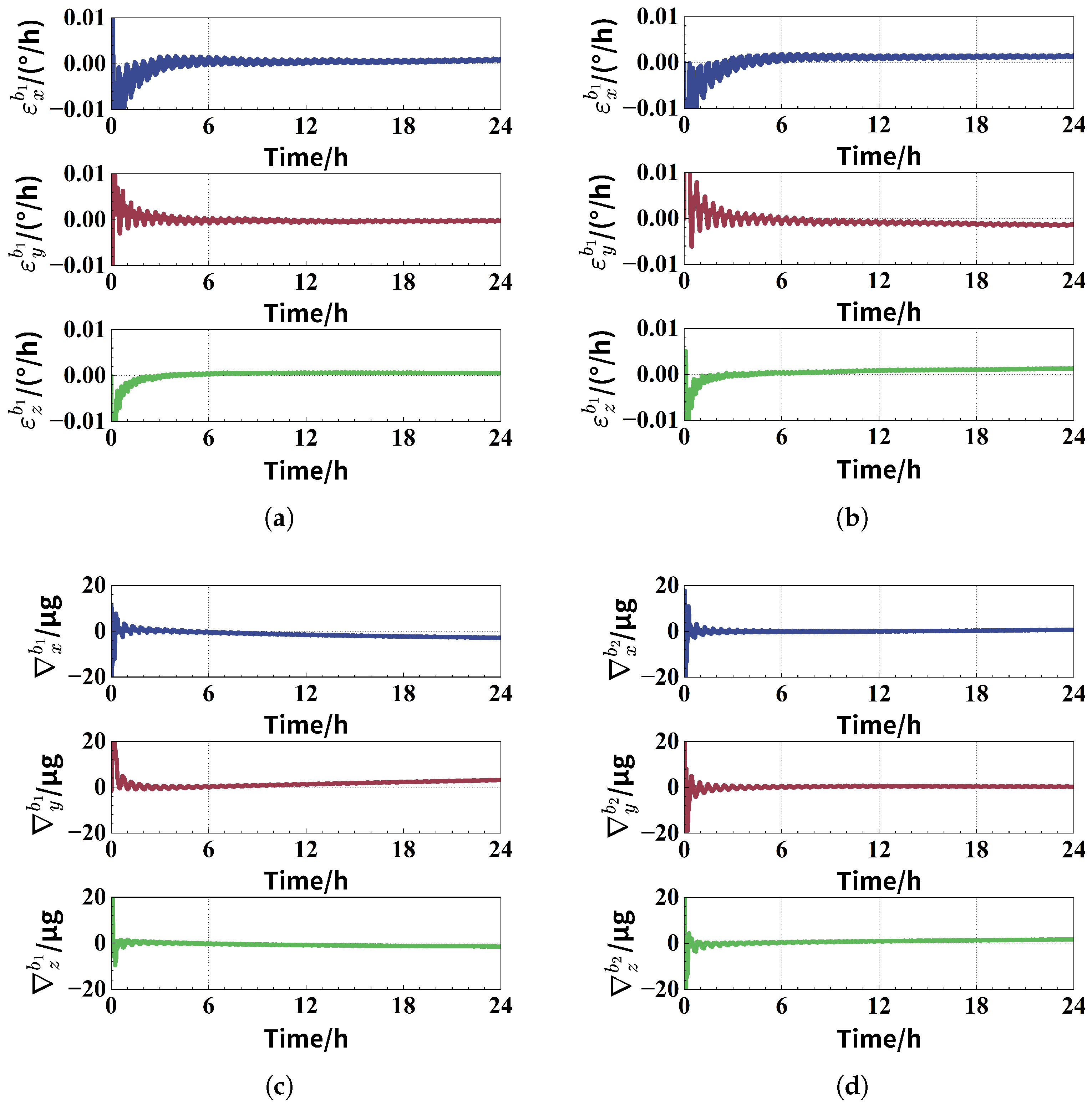
During the experiment, the alignment of the dual DRINSs lasts for 6 h to obtain the initial attitude and compensate for the gyro drifts and accelerometer biases. Following alignment, the dual DRINSs perform 24 h autonomous navigation employing the 16-sequence rotation modulation scheme. The proposed algorithm is utilized to estimate the residual gyro drifts as well as accelerometer biases of both IMUs during the navigation phase, with the results shown in
Figure 1. Although the estimated error is compensated at the end of the fine alignment, there are still residual errors as well as drift errors caused by external influences during operation as shown in the figures. However, the estimated value of the error state satisfies the inertial device performance characteristics.
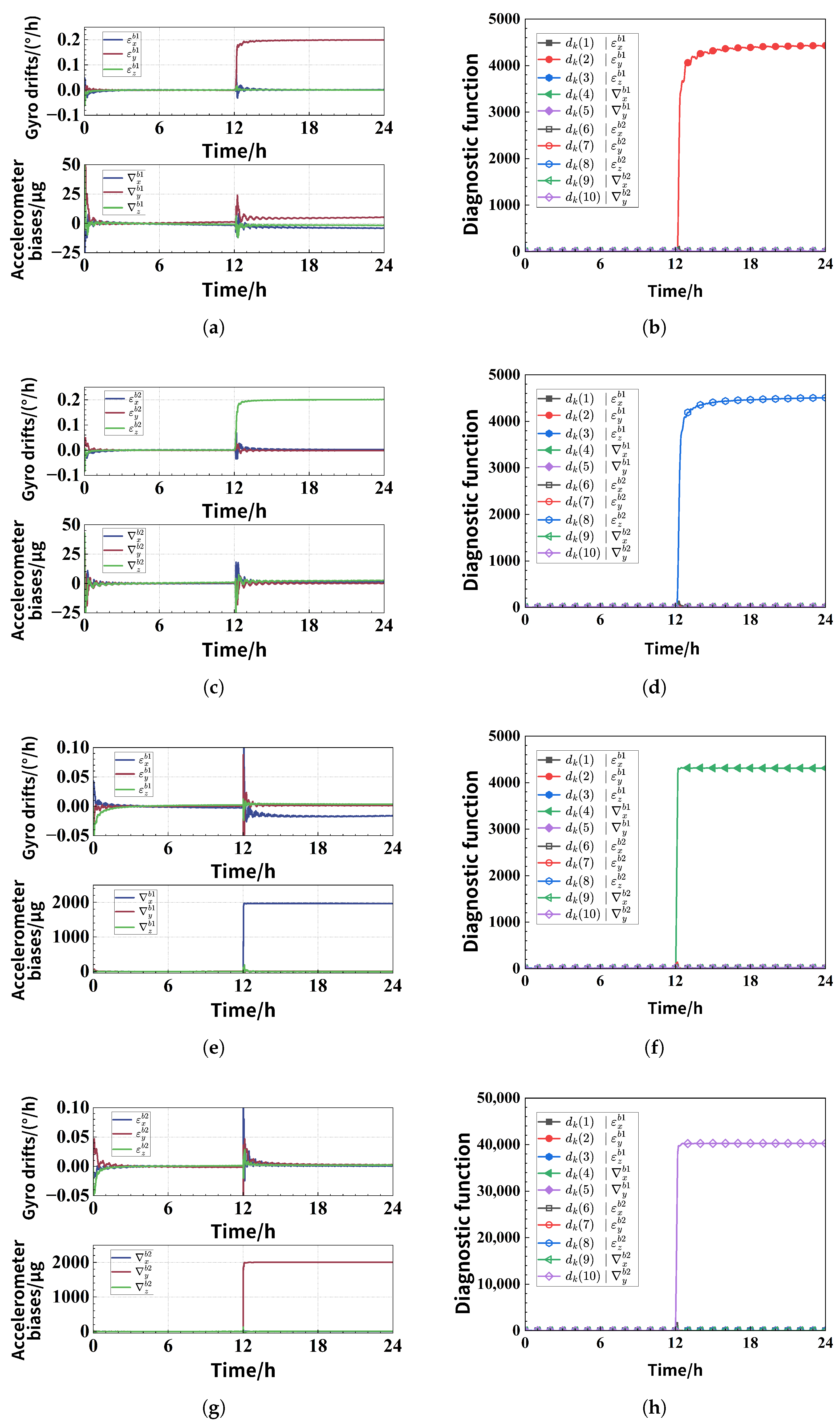
Considering the case that only one inertial device fails, the faults are added to the raw data to verify the effectiveness of the fault diagnosis algorithm. The fault occurs at
h with the gyro fault value of 0.2°/h and the accelerometer fault value of 2000 μg. The error state estimation results and diagnostic functions under four faults are given in
Figure 2, which are
y-axis gyro and
z-axis accelerometer faults for DRINS 1 and
z-axis gyro and
y-axis accelerometer faults for DRINS 2. It can be seen from the figures that the proposed algorithm could estimate the fault amplitude quickly, and the corresponding fault function value of the faulty device jumps to achieve an accurate diagnosis of the faults. The diagnostic delays for these four experiments are 851 s, 243 s, 710 s and 236 s, respectively.
To further assess the proposed fault diagnosis algorithm, a Monte Carlo simulation of 300 trials is conducted. Each trial introduces a single fault into a random device of the dual DRINSs (excluding the z-axis accelerometer). The fault time, gyro fault amplitude and accelerometer fault amplitude obey uniform distribution, i.e., , and . This stochastic injection enables robust performance assessment across diverse failure scenarios, reflecting real-world operations. In 300 trials, the algorithm achieved 98.67% diagnostic accuracy (296 successful diagnoses). Misdiagnosis and missed detection occur in three (1.00%) and one (0.33%) trial(s), respectively. The average diagnostic delay is 1360.9 s. Above all, the faults in dual DRINSs are diagnosed rapidly and accurately with the proposed algorithm.



 ,
,