Abstract
This study aims to analyze various methods, including AI, that can be used to optimize error analysis in digital twins and highlight the advantages and disadvantages of these analysis methods. Furthermore, the study aims to present an automated solution for error analysis of MATLAB/Simulink-based digital twins. This solution can make the error analysis more efficient without the use of AI, meaning that it can be used even if the digital twin is not appropriately known, which can be a considerable advantage in the current automotive industry, where complex digital twins are commonly used for the development and optimization of E/E systems during different types of in-the-Loop simulations.
1. Introduction
Today, various types of electronic and electrical (E/E) systems play a crucial role in our daily lives. The complexity of E/E systems can range from a system controlled by a single electronic control unit (ECU) to a system involving hundreds of ECUs, such as cars, airplanes, and spaceships [1,2,3].
During the development of these systems, digital twins created by using model-based design (MBD) play a critical role, notably in the early stages of the development, where the digital twins can completely replace the physical prototypes, providing a fast and cost-effective way to test different types of design and to modify the system flexibly. These is especially important in the case of safety critical systems, where virtual development and testing can not only speed up the development process and reduce the costs but also provides a safe way to optimize the control system and to find fatal errors before the system is realized, which significantly reduces the cost and dangers of testing with a real prototype [4,5].
In the case of model-based design, the E/E system must be divided into two parts, resulting in the development of two different digital twins. The first part is the digital twin of the controller, which will control the given system in the case of a real prototype. The second part, referred to as the plant, is the virtual representation of the rest of the system. It is worth noting that in many cases, the controller controls only a specific subsystem within the plant; however, to obtain realistic results, the plant must include other subsystems and components that cooperate with the controlled subsystem [6,7].
During the creation of these two digital twins, multiple factors must be taken into account; only a few of these factors will be highlighted in this article. The available information about the system is crucial to creating a realistic representation of it. However, the amount of this information is, in many cases, insufficient, while in other instances, it is excessive. This is why empirical knowledge and simplifications play a crucial role in the creation of digital twins [8,9].
The purpose of the digital twin is another key factor, especially in the case of the plant model. During the creation of the plant model, unnecessary system components must be simplified as much as possible. This is not only important for reducing the model development time, but also for minimizing potential error sources and the computational demands of the model [10].
Lastly, the potential reusability of digital twins should be noted. In the case of industries such as automotive and aerospace, it is crucial to develop digital twins that are universal and usable for multiple projects and in various stages of the x-in-the-Loop development. This can not only save time and cost but also make the development of future systems faster and easier [6,11].
As mentioned earlier, digital twins are utilized for various types of x-in-the-Loop simulations to enhance the effectiveness and speed of validating and testing electrical/electronic (E/E) systems. In the case of in-the-Loop simulations, the controller and the plant are placed in a closed loop and tested with different representations of the controller [5,12].
Figure 1 shows the relationship between different types of x-in-the-Loop simulations. As shown in the figure, in the case of model-in-the-Loop (MIL) simulation, both the controller and the plant of the system are created in a suitable environment, such as MATLAB/Simulink [13]. This type of simulation can be performed using a simple computer and does not require any specialized equipment. In the case of software-in-the-Loop (SIL), the model of the controller is replaced by the code that will be used on the future controller. If the plant model was correctly designed, SIL can already be used to test many key functionalities of the controller [13,14]. In the hardware-in-the-Loop (HIL) simulation, the model of the controller is replaced with the real controller. Consequently, the simulation must run in real time to ensure the proper functionality of the ECU, requiring a simulator capable of real-time simulations [15,16]. Depending on the system’s complexity, multiple real ECUs or other real components can be integrated, further increasing the simulation’s complexity. As the validation tests progress from MIL to HIL, the complexity and cost of simulation and testing increase with each subsequent validation phase; therefore, it is crucial to identify the majority of errors in the early stages of validation [13].
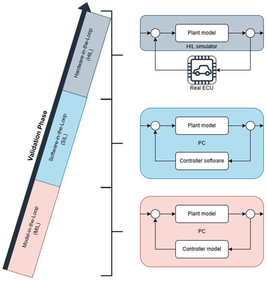
Figure 1.
Different types of x-in-the-Loop simulations.
Most studies in the field of in-the-Loop simulations and digital twins focus on the use of simulations [17] and the creation of proper digital twins [18]; however, there is limited focus on error analysis of the digital twins themselves. This is the reason why this study focuses on establishing an automated error analysis solution that makes the analysis more convenient and practical.
2. Materials and Methods
As previously pointed out, this research focuses on the error analysis of the digital twin of the plant model used for x-in-the-Loop simulations for multiple reasons. First of all, the controller model is replaced after the MIL simulations, so it can not cause any problems in the later stages. An error in the controller model will be noticed at the latest during the SIL tests [5]. In contrast, the plant model is used in multiple validation stages, so it must work with different representations of the controller and be suitable for real-time applications as well. Last but not least, the plant models must not only be continuously improved but also periodically updated with new features.
To analyze the complexity of error analysis in plant models, a series RLC circuit was taken as an example, as shown in Figure 2.
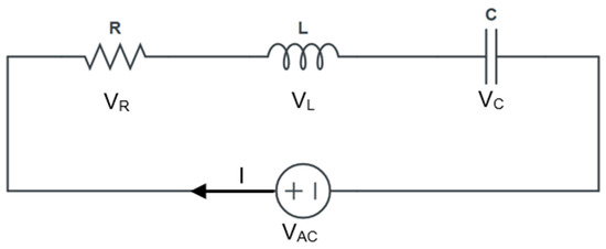
Figure 2.
Series RLC circuit.
This system can be described by using the following equations:
This type of system was chosen because it is an excellent example of a simple plant model and can be easily modeled in MATLAB/Simulink 2023a. However, it contains enough complexity to demonstrate the challenges of error analysis in MATLAB/Simulink-based digital twins. The model being created in MATLAB/Simulink is shown in Figure 3.
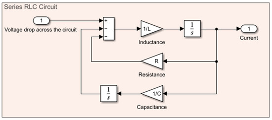
Figure 3.
Series RLC circuit in MATLAB/Simulink.
For the analysis of errors within digital twins, two different approaches were investigated. As a result of this investigation, a third approach was developed, which is discussed in Section 3.
2.1. Error Analysis Without Automation
The most straightforward approach to analyzing an error within the plant model is to conduct a manual analysis by using plotters in the simulation environment, following the path of the faulty signal in the modeling environment. In the case of MATLAB/Simulink, this can be achieved by using the “Highlight Signal to Source” command to identify the source of the error or by using the “Highlight Signal to Destination” command to investigate its effect on subsequent system elements.
However, this approach can be highly time-consuming and ineffective in the case of complex multilevel models, as it does not protect loopbacks, leading to repeated checks of the same blocks and variables when they are used in multiple models. That is why this approach can be viable only in the case of simple models.
2.2. Error Analysis by Using Artificial Intelligence (AI)
Nowadays, AI is a popular method for solving almost any problem and challenge. By having the necessary amount of data and building up a proper AI model for the given application, many problems can be easily solved in a fast and efficient way.
However, using AI can have multiple drawbacks in the case of error analysis. Firstly, training an AI requires a substantial amount of data and training time, which can be a significant issue in the case of a continuously evolving and growing digital twin. Moreover, issues such as overfitting can significantly reduce the usability of a given AI solution. Last but not least, an AI-based solution can be beneficial in error analysis for a given plant model, but may be entirely useless in the case of another one, as it is challenging to create a universally usable AI solution for every use case [19].
2.3. Creating an Own Method for Error Analysis of Digital Twins
After investigating the two possible approaches mentioned earlier, it was noted that neither can secure the necessary accuracy, speed, and flexibility. The manual approach lacks speed, while the AI-based solution can only provide the required precision, speed, and flexibility if it undergoes regular checkups after each significant modification of the plant model. In case of inaccuracy, it receives the necessary retraining with the appropriate amount of new data.
This is the reason why it was decided to create a third approach, striking the right balance between the previously mentioned key factors without the need for training an AI, but with more human involvement compared to the AI-based approach.
3. Results and Discussion
As previously mentioned, it was decided to develop a new method for analyzing the errors within the digital twin models. In the case of this method, it was decided to handle the MATLAB/Simulink model of the digital twins as a complex system of graphs, where every level of the model is represented as a directed graph. To visualize this approach, Figure 4 was created, which represents the series RLC circuit of Figure 3 in the form of a directed graph. The green circle represents the input of this system, and the blue circle represents the output of the system. The yellow circles indicate all the other blocks within the system. Following this methodology, even the digital twins of the most complex systems can be handled as a complex system of directed graphs, and so they can be analyzed as well.
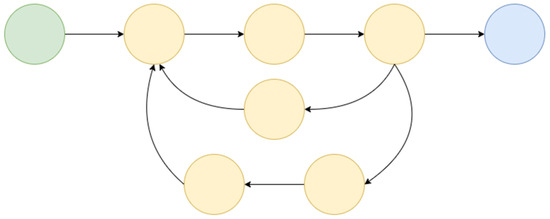
Figure 4.
The series RLC circuit made in MATLAB/Simulink is represented as a directed graph.
Handling the given system as a directed graph brings multiple key advantages. First, it is helpful to understand the interaction between the different parts of the system, which in turn facilitates a better understanding of the part of the model being analyzed. Moreover, this method can be used to gain a better understanding of a given digital twin, particularly one with which the error analyzer is less familiar. This can be highly beneficial, because in the case of a complex system, the plant of the system is designed by multiple teams, so the analyzer of the problem might have only basic knowledge about the given part of the system, but he has no knowledge about how the given part of the digital twin was designed and structured. Last but not least, an automated solution was created based on this methodology, which enables the faster analysis of the digital twin and, consequently, the more time-effective correction of errors. It should be noted that the method being developed requires the active involvement of an operator, but it can expedite the analysis process.
Using this error analysis tool, five tests were performed. In each case, a hidden logical error within the MATLAB/Simulink model of the digital twin led to unexpected behavior. One test was performed entirely manually, while the other used the error analysis tool in its current state. The results indicate that the current tool can reduce the time spent on model analysis by approximately 25%, as illustrated in Figure 5.
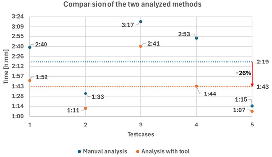
Figure 5.
Comparison of the two analyzed methods, manual (blue) and tool (green). The average analysis time of the two different approaches is shown with dotted lines.
However, it is believed that the time spent on model analysis will decrease further in the long run due to multiple reasons. Firstly, users of the tool must become familiar with the capabilities it offers. Furthermore, it is planned to optimize the tool further and enhance its capabilities. Last but not least, it is challenging to measure the time saved by using this tool because the efficiency and speed of the analysis depend strongly on factors such as the complexity of the problem, the complexity of the digital twin, and the analyst’s experience. This is the reason why the design of experiments (DOE) will be used in future tests to make the results of different tests more precise and comparable with each other.
4. Conclusions
Based on the results, it can be stated that a new method for analyzing errors in MATLAB/Simulink-based digital twins has been created. This method not only provides an accurate, fast, and flexible way to analyze and identify errors within the digital twin model, but it can also be applied universally to any MATLAB/Simulink-based model without the need for retraining or accuracy checks. It is worth reiterating that this new method requires the active involvement of an operator with basic knowledge of the digital twin being analyzed.
In conclusion, it can be stated that the method being developed can significantly reduce error analysis time in the case of MATLAB/Simulink-based digital twins. Our plan for the future is to create a connection between the offline and online models of digital twins, which can lead to a further reduction in analysis time. Furthermore, it is planned to investigate the combination of this new methodology with AI in some of the use cases. By recognizing this, it will be possible to further enhance the effectiveness and suitability of this method for other use cases.
Author Contributions
Conceptualization, J.R.L. and D.F.; methodology, J.R.L. and I.S.; software, J.R.L. and I.S.; validation, J.R.L.; formal analysis, J.R.L.; investigation, J.R.L.; resources, J.R.L.; data curation, J.R.L.; writing—original draft preparation, J.R.L.; writing—review and editing, I.S.; visualization, J.R.L.; supervision, D.F. All authors have read and agreed to the published version of the manuscript.
Funding
The publication was created in the framework of the Széchenyi István University’s VHFO/416/2023-EM_SZERZ project entitled “Preparation of digital and self-driving environmental infrastructure developments and related research to reduce carbon emissions and environmental impact” (Green Traffic Cloud).
Institutional Review Board Statement
Not applicable.
Informed Consent Statement
Not applicable.
Data Availability Statement
Data for this study is not publicly available.
Conflicts of Interest
The authors declare no conflict of interest. The funders had no role in the design of the study, in the collection, analyses, or interpretation of data, in the writing of the manuscript, or in the decision to publish the results.
Abbreviations
| VR | Voltage drop across resistor [V] |
| VL | Voltage drop across inductor [V] |
| VC | Voltage drop across capacitor [V] |
| VAC | Voltage drop across the circuit [V] |
| I | Current [A] |
| L | Inductance [H] |
| R | Resistance [Ω] |
| C | Capacitance [F] |
References
- Bucaioni, A.; Ciccozzi, F.; Sentilles, S.; Crnkovic, I. Modelling Centralised Automotive E/E Software Architectures. Adv. Eng. Inf. 2024, 59, 102289. [Google Scholar] [CrossRef]
- Farooq, U. Model Based Verification of Electronic Control Unit (ECU) in High Lift Systems: Verification and Validation. In Proceedings of the 2017 IEEE International Systems Engineering Symposium (ISSE), Vienna, Austria, 11–13 October 2017; pp. 1–5. [Google Scholar] [CrossRef]
- Mauser, L.; Wagner, S. Centralization Potential of Automotive E/E Architectures. J. Syst. Softw. 2025, 219, 112220. [Google Scholar] [CrossRef]
- Dubois, H.; Goknil, A.; Sabetzadeh, M.; Briand, L. A Model for Requirements Traceability in a Heterogeneous Model-Based Design Process: Application to Automotive Embedded Systems. In Proceedings of the 2010 15th IEEE International Conference on Engineering of Complex Computer Systems, Oxford, UK, 22–26 March 2010; pp. 233–242. [Google Scholar] [CrossRef]
- Shylla, D.; Jain, A.; Shah, P.; Sekhar, R. Model in Loop (MIL), Software in Loop (SIL) and Hardware in Loop (HIL) Testing in MBD. In Proceedings of the 2023 4th IEEE Global Conference for Advancement in Technology (GCAT), Bangalore, India, 6–8 October 2023; pp. 1–6. [Google Scholar] [CrossRef]
- Mihai, S.; Yaqoob, M.; Hung, D.V.; Davis, W.; Towakel, P.; Raza, M.; Karamanoglu, M.; Barn, B.; Shetve, D.; Prasad, R.V.; et al. Digital Twins: A Survey on Enabling Technologies, Challenges, Trends and Future Prospects. IEEE Commun. Surv. Tutor. 2022, 24, 2255–2291. [Google Scholar] [CrossRef]
- Askaripoor, H.; Hashemi Farzaneh, M.; Knoll, A. E/E Architecture Synthesis: Challenges and Technologies. Electronics 2022, 11, 518. [Google Scholar] [CrossRef]
- Botín-Sanabria, D.M.; Mihaita, A.S.; Peimbert-García, R.E.; Ramírez-Moreno, M.A.; Ramírez-Mendoza, R.A.; Lozoya-Santos, J.D.J. Digital Twin Technology Challenges and Applications: A Comprehensive Review. Remote Sens. 2022, 14, 1335. [Google Scholar] [CrossRef]
- Zhang, X.; Zhang, J.; Wang, Y. Model-Based Requirements Capture and Validation Approach Based on PLM Platform Applied in the Civil Aircraft. In Proceedings of the 2019 6th International Conference on Information Science and Control Engineering (ICISCE), Shanghai, China, 20–22 December 2019; pp. 375–379. [Google Scholar] [CrossRef]
- Berriel, R.O.; Delarue, P.; Bouscayrol, A.; Brocart, C. Model Simplifications of a Subway Vehicle for Computation of Energy Consumption. In Proceedings of the 2021 IEEE Vehicle Power and Propulsion Conference (VPPC), Gijon, Spain, 25–28 October 2021; pp. 1–5. [Google Scholar] [CrossRef]
- Szalay, Z. Next Generation X-in-the-Loop Validation Methodology for Automated Vehicle Systems. IEEE Access 2021, 9, 35616–35632. [Google Scholar] [CrossRef]
- Rehberg, L.; Brem, A. Industrial Prototyping in the German Automotive Industry: Bridging the Gap between Physical and Virtual Prototypes. J. Eng. Technol. Manag. 2024, 71, 101798. [Google Scholar] [CrossRef]
- Bringmann, E.; Krämer, A. Model-Based Testing of Automotive Systems. In Proceedings of the 2008 1st International Conference on Software Testing, Verification, and Validation, Lillehammer, Norway, 9–11 April 2008; pp. 485–493. [Google Scholar] [CrossRef]
- Chen, X.; Salem, M.; Das, T.; Chen, X. Real Time Software-in-the-Loop Simulation for Control Performance Validation. Simulation 2008, 84, 457–471. [Google Scholar] [CrossRef]
- German, R.; Kalogiannis, T.; Bouscayrol, A.; He, J.; Tournez, F.; Berecibar, M.; Husar, C.; Ciocan, M.; Costa, S.; Genic, A.; et al. A Flexible Cloud-Based HIL Testing of Batteries for Various Electrified Vehicles. IEEE Trans. Veh. Technol. 2024, 73, 4610–4620. [Google Scholar] [CrossRef]
- Bouscayrol, A. Different Types of Hardware-In-the-Loop Simulation for Electric Drives. In Proceedings of the 2008 IEEE International Symposium on Industrial Electronics, Cambridge, UK, 30 June–2 July 2008; pp. 2146–2151. [Google Scholar] [CrossRef]
- De Farias, A.B.C.; Rodrigues, R.S.; Murilo, A.; Lopes, R.V.; Avila, S. Low-Cost Hardware-in-the-Loop Platform for Embedded Control Strategies Simulation. IEEE Access 2019, 7, 111499–111512. [Google Scholar] [CrossRef]
- Fadili, S.; German, R.; Bouscayrol, A. HiL Testing of a High C-Rate Battery For the Nissan Leaf. In Proceedings of the 2022 IEEE Vehicle Power and Propulsion Conference (VPPC), Merced, CA, USA, 31 October–3 November 2022; pp. 1–6. [Google Scholar] [CrossRef]
- Naser, M.Z.; Alavi, A.H. Error Metrics and Performance Fitness Indicators for Artificial Intelligence and Machine Learning in Engineering and Sciences. Archit. Struct. Constr. 2023, 3, 499–517. [Google Scholar] [CrossRef]
Disclaimer/Publisher’s Note: The statements, opinions and data contained in all publications are solely those of the individual author(s) and contributor(s) and not of MDPI and/or the editor(s). MDPI and/or the editor(s) disclaim responsibility for any injury to people or property resulting from any ideas, methods, instructions or products referred to in the content. |
© 2025 by the authors. Licensee MDPI, Basel, Switzerland. This article is an open access article distributed under the terms and conditions of the Creative Commons Attribution (CC BY) license (https://creativecommons.org/licenses/by/4.0/).