Abstract
The condition of the lubricating oil is a critical factor for the lifetime of internal combustion engines. The timing chain is a particularly sensitive component to the oil quality, so it can be used as an indicator when the effect of the oil quality and contamination on the engine has to be examined. For this purpose, a unique timing chain test bench was developed at the Department of Propulsion Technology at Széchenyi István University. This paper presents the function of this test equipment and the results of the first tests aimed at comparing the wear of a diesel engine’s timing chain using various soot-contaminated engine oils. A significant difference in wear was detected after 25 h of operation using oils with different soot contents. In the case of oil comparison studies, the chain test bench can be a cheap and fast alternative to engine dynamometer tests.
1. Introduction
The use of alternative fuels in the internal combustion engines of passenger cars presents new challenges to engine and lubricant developers too. The fuel interacts with the lubricating oil and thus with all the components connected to the lubrication system. All engines have a certain degree of oil dilution, which is the result of fuel getting into the oil. The fuel mostly gets on the cylinder wall and from there into the sump after a cold start or during high-load operation. The dilution of the oil is not a new phenomenon; however, the fuel has not changed significantly in the past decades, so the dilution and its consequences were well known. Both engines and engine lubricants were developed considering it [1,2].
Hydrogen can be an ultimate solution as a carbon-neutral fuel [3]. However, it might need several decades to develop solutions for clean, safe, and economic production, transport, and storage for hydrogen. The transportation sector needs medium-term solutions to decrease carbon emissions. The next step towards carbon-neutral transport could be the introduction of E20 (20% ethanol, 80% gasoline) [4] and other synthetic fuels [5]. These must be compatible not only with newly developed engines but also with engines of vehicles that have been on the road for years or decades. Before the introduction of a new fuel, it is necessary to carry out various functional tests to observe its combustion behavior, deposit formation, and chemical compatibility with the components of the fuel system and with the motor oil. Fuel in the motor oil affects its lubricating properties; therefore, it is highly important to conduct tribological tests with different fuel-oil blends. Compatibility with lubricated engine components can be investigated, obviously with engine dynamometer tests, which enable testing of all engine components [6,7,8]. This, on the other hand, has disadvantages such as the high initial and operating costs of the engine dynamometer (about 5 to 20 times higher than component tests), significant fuel consumption and test duration, and the time and personnel required to disassemble and assemble the engine. The invested time and costs spent can be significantly reduced when engine components are tested separately instead of the entire engine [9,10]. Certainly, component tests also have their disadvantages. The conditions of the test, the load, and the stress cannot usually fully reflect the real conditions, due to simplifications that are beneficial from a repeatability point of view. Therefore, it is usually necessary to combine various test methods during the development process. If the quality of the lubricating oil is in focus, the timing chain is the ideal part for lubricant tests, as it is particularly sensitive to oil quality in terms of wear. Usually, the timing chain is used as an indicator during the development of lubricating oils and oil additives [11]. Thus, the cost and duration of development, as well as the environmental impact, can be reduced using a timing chain test bench.
2. Methodology
2.1. Function and Types of Chain Test Benches
The Department of Propulsion Technology has been developing a timing chain test bench, which will primarily serve the development of alternative fuels and the research of their effect on the motor oil and, indirectly, on the wear of engine components.
The task of timing chain test benches is to load and wear the chains in order to compare the chain wear under different predefined conditions that are typically chain force, chain speed, quality, and temperature of the lubricating oil, and possibly oil contaminants. Chains are typically tested on test benches at a constant or intermittently changing speed and load. They are usually driven by an electric motor, the speed of which can be adjusted [12,13]. Chain force can be created and adjusted in several ways, as it is shown in Figure 1.
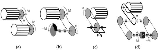
Figure 1.
Possible loading schemes of a chain test bench: (a) braking motor; (b) mechanical brake; (c) applying a steady force by increasing the distance of the axes; (d) rotating the chains in relation to each other with an adjustable clutch. The clutch (marked by “C”) can be adjusted mechanically or hydraulically, and it needs two chains to test [14].
2.2. Chain Test Bench with Hydraulic Chain Load Control
The chain test bench at the Department of Propulsion Technology works according to the scheme. In Figure 1d, a sprocket is placed at both ends of the solid shaft driven by the electric motor that is connected by two chains to the sprockets on the two half shafts. Two chains are tested simultaneously. The shaft with the hydraulic clutch is adjustable on a pair of linear guides, with a self-closing threaded spindle. The driven shaft can be moved on a pair of linear guides with the help of a trapezoidal spindle. With that, the distance of the shafts and thus the starting tension of the chain can be precisely adjusted. The driven shaft consists of two half shafts, and the two sides are connected by a tensioner (marked by “C” on Figure 1d). The tensioner can be either mechanical or hydraulic. A mechanical coupling would be a simple and cheap solution, but it has the drawback that it cannot keep the chain force constant. With increasing chain wear and elongation, the level of tension decreases, so it has to be readjusted periodically. Using a hydraulic coupling is more complex, but the chain force can either be kept constant during the entire test, or it can be varied continuously, or a dynamic load profile can be realized.
On the chain test bench of the Department of Propulsion Technology (Figure 2), the tensioner is a vane-type cam phaser from an internal combustion engine. The function of the tensioner is to twist the two half shafts relative to each other, thereby tensioning the chains located on both sides. Consequently, the load on the two chains will be the same. However, on one chain, the upper strand will be tight, and the lower strand will be slack, and opposite on the other chain.
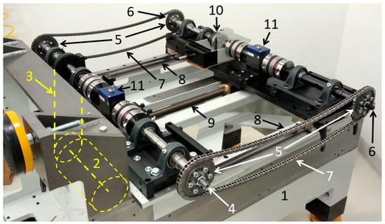
Figure 2.
Test bench structure (without safety covers for visibility of the components): 1—frame, 2—electric motor (under the frame), 3—V-belt drive (under the frame), 4—drive shaft, 5—sprockets, 6—driven shaft (adjustable, consisting of two half shafts), 7—chains under test, 8—linear guides, 9—trapezoidal spindle, 10—hydraulic tensioning clutch (cam phaser), 11—torque sensors [14].
A further advantage of this arrangement is that, in the case of a constant chain force, the angular position of the two sides of the tensioner changes proportionally to the wear (elongation) of the chains, and so does the orientation of the sprockets relative to each other. This makes it possible to measure the wear of the chains during operation, as long as a sensor that can measure the orientation of the sprockets relative to each other is installed at each of the sprockets. This solution for online wear measurement is being developed on the test bench.
The cam phaser used as a hydraulic tensioning clutch is a key part of the chain test bench; therefore, its design is presented in detail in Figure 3. Controlled high-pressure oil leads to the cam phaser (6) necessary for operation through radial holes formed on its shaft (11) through the journal bearing block (8). The tensioning force in the chain depends on the level of the oil pressure. Although the chain force is calculated from the torque measured by the torque sensor, for the purpose of double-checking and error detection, the oil pressure is also measured on the forward and return lines with pressure sensors (9). One half-shaft is attached to the phaser shaft (11) by a coupling (12), with a sprocket at the end. The other half-shaft (3), with the other sprocket at the end, is connected to the phaser housing (6) by an adapter (5).
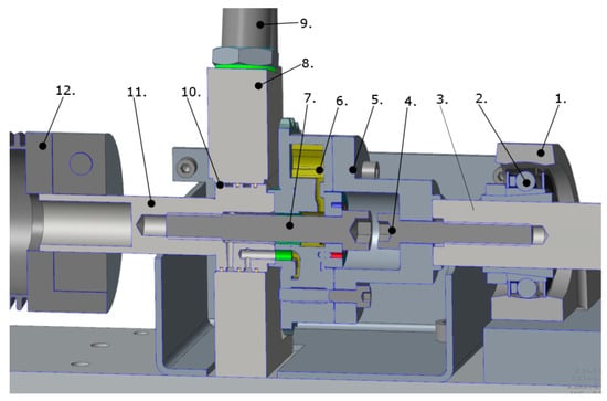
Figure 3.
The hydraulic cam phaser with chain tensioning function and its associated components: 1—bearing housing, 2—ball bearing, 3—half shaft, 4—screw, 5—adapter, 6—phaser housing, 7—screw, 8—journal bearing block, 9—pressure sensor, 10—sealing ring, 11—phaser shaft, 12—clutch [15].
The controlled oil pressure on the blades of the phaser rotor creates a torque on the rotor shaft, causing the shaft to rotate relative to the phaser housing. Since one half-shaft of the driven shaft is connected to the phaser rotor and the other to the housing, the two half-shafts rotate with them in the opposite direction, together with the sprockets placed at their ends. Since there is a chain on both sprockets connecting the two shafts, the phaser rotation continues until the backlash in the bearings, in the joints of the chains, and between the chain and sprockets disappears, and the elastic deformation of the components occurs.
The adjustable oil pressure is provided by a Rexroth ABSKG-4379-0-C hydraulic power unit, which was specially designed by Bosch Rexroth for this test bench. It includes an oil tank, an electric motor-driven pump, an oil filter, a pressure control valve, and a direction-switch control valve. The latter allows the direction of chain tension to be changed.
In the middle of the driving and driven shafts, there is an HBM T20WN torque sensor, connected with two shaft couplings. The chain force—the regulated value during the tests—can be calculated from the torque measured by these torque sensors. Two are necessary because this provides the opportunity to measure the friction losses of the test bench and to detect possible errors and malfunctions if the values measured by the two sensors do not match.
2.3. First Tests on the Chain Test Bench
The commissioning of the test bench was a long process, characterized by continuous troubleshooting, searching for the source of problems, finding solutions, and troubleshooting again. At the time of writing this article, the most important subsystems of the test bench were operational, which means that the test bench is able to drive the chain at the specified speed, the hydraulic control system is able to load the chains with the set chain force, and the lubricating oil circuit is able to supply the chains with engine oil conditioned up to 100 °C. This made the test bench suitable for carrying out the first tests, the purpose of which is to prove that the test bench is able to operate continuously, and it is suitable for examining the effect of different oil qualities on timing chains.
2.4. Test Parameters
During the measurements, timing chains from an Audi V6 TDI engine were used. The reason for this is that several measurements have been carried out with this type of chain in recent years on an engine dynamometer as well as on a tribometer [16,17], and its results can serve as a reference for validation. A 1:1 ratio of driving to driven sprocket diameter was chosen for the sake of simplicity, as the utilized parts are commercially available timing chain sprockets of the camshaft. The underlying cause is that the crankshaft sprocket is integrated into the crankshaft; therefore, it would be complicated and expensive to remove from the crankshaft, while the camshaft sprockets are mounted, and they only need to be attached to the ends of the half-shafts of the test bench with the help of adapters. Since in this case there was no reason for a 1:2 ratio, camshaft sprockets were used on both axles (Figure 4).
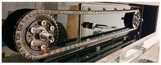
Figure 4.
Camshaft sprockets and timing chain mounted on a test bench, the oil nozzle is visible between the two sprockets [14].
The diameter of the sprockets was 109 mm. The pitch of the chains was 9.525 mm, and they consisted of 174 links, so the total chain length was 1657 mm.
The purpose of the tests was to verify the stable and reliable operation of the test bench and the reliability of the results obtained. Since the test bench tests two chains at the same time and their lubrication is provided by a common oil circuit, the wear of the chains can be compared immediately in pairs. If the two chains behave similarly, then similar wear is measured on them, so it is not necessary to repeat the test. The test parameters (Table 1) are based on the real working conditions of the chains. A total of 1000 rpm rotational speed on the camshaft sprocket means 2000 rpm engine speed, which is commonly used in diesel passenger cars. A total of 500 N is a high load compared to the average of normal operation (100–300 N), but it does not reach the peak load during operation, which is around 1500 N for the chain used [14]. A total of 100 °C is the normal oil temperature in a working engine.

Table 1.
Test parameters for the first tests performed on the chain test bench.
During the test, the test bench was able to keep controlled variables steady: the speed fluctuation was 1 rpm, the oil temperature fluctuation was within 1 °C, and the temperature difference in the lubricating oil entering the two chain boxes was typically around 0.5 °C, but did not exceed 3 °C. The fluctuation of the chain force was relatively large, approximately ±100 N, i.e., it typically fluctuated between 400 and 600 N, but the average value was 500 N. The relatively large fluctuation is a consequence of the polygon effect of the chain drive, i.e., it results from the specific geometry of the sprocket and the chain. This is confirmed by the fact that the frequency of the torque oscillation changed in direct proportion to the speed, while the amplitude remained constant.
For the test series, 10 pieces of new timing chains (marked as Nr. 1 to 10) were prepared and measured with a chain length measuring device.
The aim of the first tests was to determine the operating time required for an evaluable wear, so relatively long, 50 h tests with two types of oil were conducted. One was new Shell Helix Ultra 0W-30 oil (the factory oil of the engine with this chain); the other one was the same type of oil that had been used in an engine exercised on a dynamometer for 200 h (corresponds to an oil change interval of 15,000 km). The latter’s soot content was 2.95 m/m% according to the Lubcheck test performed by MOL. This is just within the 3% limit specified by the engine manufacturer.
The kinematic viscosity of the used oil was higher compared to that of the new oil (80 mm2/s at 40 °C and 13.7 mm2/s at 100 °C while these values of the new oil are 60 mm2/s and 11.9 mm2/s) due to the soot content. The oil’s TBN (total base number) and other additives and metallic wear particle content were within the normal interval; fuel and water content were not detectable.
After the 50 h tests, 25 h tests were performed with the same oils as the first, and additionally, with the new Shell 0W-30 oil mixed with 3 m/m% and 1.5 m/m% carbon black. Before the tests, the chain boxes were cleaned of the oil residues used in the previous test. The oil pipes were emptied and flushed with clean oil, and secondly with a smaller amount of the oil used for the next test, so that the test would not be affected by the residue of the oil used in the previous test.
3. Results
3.1. Comparative Tests with Oil Used for 200 h in an Engine to New Oil
Chain elongation measurement was performed after the tests with the same chain length measuring device as before the tests. The results of the chain elongation measurement before and after the 50 h tests for the new oil and oil used for 200 h in the engine (2.95 m/m% soot content) are summarized in Table 2.
Table 2.
Chain wear measured for the new and the 200 h used oil after 50 h of operation on a timing chain test bench.
Based on the results, it can be stated that 50 h tests are not enough to develop measurable wear when running with new oil. This is explained by the resolution of the dial gauge applied on the chain length measuring device, which is 0.01 mm. (A dial gauge is used to measure the change in the axis distance between the two disks holding the chain on the device.) Considering this to be the smallest detectable change in axis distance, the smallest detectable elongation per chain link can be calculated from it, which in this case is 0.14 μm. Dividing this value by the 50 h test time results in a wear rate of 2.8 nm/h. The smallest detectable value of the elongation of the entire chain (0.14 μm × 174 links) is 0.024 mm, which is 0.0015% in specific elongation. These are the values of the smallest detectable wear, which in this case is less with new oil after 50 h.
The oil used for 200 h in an engine with a 2.95% soot content caused significant wear on the chains. The average change in axis distance measured on the measuring device with these chains is 0.425 mm and 0.455 mm (Table 2, chains Nr 4 and 10), which corresponds to a wear rate of 118 nm/h and 126 nm/h. This is 12 times higher than the average wear limit for the chain’s service life, which is approximately 10 nm/h [16]. The extremely high value is explained by the high soot content, as well as the high average load, which results in accelerated wear. Therefore, it is worth conducting further tests with oils aged in engines with lower and higher soot contents so that the relationship between soot content and wear can be precisely determined.
3.2. Comparative Tests with Diesel Soot and Carbon Black
To achieve a more accurate picture of the relationship between soot content and wear, and to gain experience with the sensitivity of the new method, tests with oil mixed with 1.5 m/m% and 3 m/m% industrial carbon black (CB—carbon black) were also conducted. Based on the results of the previous test, 25 h tests were performed, since this duration promised to be sufficient to create enough wear to be detectable with a chain length measuring device. The results are summarized in Table 3. The results show that the wear of two chains tested simultaneously on the timing chain test bench shows only a minimal difference (in the worst case, 6%), which is important for the reliability of the test.
Table 3.
Chain wear was measured with various soot-containing oils after 25 h of operation on a timing chain test bench.
4. Discussion and Conclusions
Based on the results, it can be stated that the abrasive effect of carbon black is greater than that of the diesel soot used in the current tests, since more wear was achieved with 1.5% carbon black than with the 2.95% soot content generated in the engine. Future work is planned to examine the effect of the type and concentration of soot in detail in further research in order to establish the exact relationship between chain wear and soot type and soot content.
The unique solution of the timing chain test bench is the controllable hydraulic chain tensioner, which has not been used in this form until now. The first tests carried out with the chain test bench have proven that the cam phaser is perfectly suitable as a hydraulic tensioning clutch for implementing the load on the chains. The test bench was designed so that it is not only suitable for testing timing chains but also for testing other drive chains or belts, even timing belts running dry or in oil. This is made possible by the widely adjustable axis distance and the shaft end design, on which any type of sprocket or pulley can be mounted with adapters. Dimensions are limited to 150 mm sprocket diameter and 735 mm axis distance.
Author Contributions
Conceptualization, L.P. and C.T.-N.; methodology, L.P.; software, L.B.; investigation, L.B.; writing—original draft preparation, L.P.; writing—review and editing, C.T.-N.; visualization, L.P.; supervision, C.T.-N. All authors have read and agreed to the published version of the manuscript.
Funding
This article is published in the framework of the project “Synthetic fuels production and validation in cooperation between industry and university”, project number “ÉZFF/956/2022-ITM_SZERZ”.
Institutional Review Board Statement
Not applicable.
Informed Consent Statement
Not applicable.
Data Availability Statement
Data for the study are available upon request from the corresponding author.
Acknowledgments
Measurements for this study were conducted with the support of the Engine Dynamometer Laboratory of Széchenyi István University.
Conflicts of Interest
The funders had no role in the design of the study; in the collection, analyses, or interpretation of data; in the writing of the manuscript; or in the decision to publish the results. The authors declare no conflict of interest.
References
- Ljubas, D.; Krpan, H.; Matanovic, I. Influence of engine oils dilution by fuels on their viscosity, flash point and fire point. NAFTA 2010, 61, 73–79. [Google Scholar]
- ADDINOL. What Is Oil Dilution? Available online: https://addinol.de/en/products/lubricants-for-the-automotive-sector/engine-oil/oil-dilution/ (accessed on 9 May 2025).
- Zöldy, M.; Virt, M.; Lukács, K.; Szabados, G. A Comprehensive Analysis of Characteristics of Hydrogen Operation as a Preparation for Retrofitting a Compression Ignition Engine to a Hydrogen Engine. Processes 2025, 13, 718. [Google Scholar] [CrossRef]
- Why Raising the Alcohol Content of Europe’s Fuels Could Reduce Carbon Emissions. Available online: https://projects.research-and-innovation.ec.europa.eu/en/horizon-magazine/why-raising-alcohol-content-europes-fuels-could-reduce-carbon-emissions (accessed on 14 July 2024).
- Niethammer, B.; Wodarz, S.; Betz, M.; Haltenort, P.; Oestreich, D.; Hackbarth, K.; Arnold, U.; Otto, T.; Sauer, J. Alternative Liquid Fuels from Renewable Resources. Chem. Ing. Tech. 2018, 90, 99–112. [Google Scholar] [CrossRef]
- Schwarze, H.; Brouwer, L.; Knoll, G.; Kopnarski, M.; Schlerege, F.; Müller-Frank, U.; Emrich, S. Lubricant degradation and wear behaviour in a spark-ignition engine. MTZ Worldw. 2008, 69, 60–67. [Google Scholar] [CrossRef]
- Schwarze, H.; Brouwer, L.; Knoll, G.; Longo, C.; Kopnarski, M.; Emrich, S. Effect of ethanol fuel E85 on lubricant degradation and wear in spark-ignition engines. MTZ Worldw. 2010, 71, 56–61. [Google Scholar] [CrossRef]
- Gergye, T.; Dreyer, M.R.; Kehrwald, B.; Optatzy, W. Analysis of the Wear Behavior of Combustion Engine Components Using Radionuclide-Technique. In Lecture Notes in Electrical Engineering, Proceedings of the FISITA 2012 World Automotive Congress, Beijing, China, 27–30 November 2012; Springer: Berlin/Heidelberg, Germany, 2012; Volume 189, pp. 171–181. [Google Scholar]
- Weber, C.; Herrmann, W.; Stadtmann, J. Experimental Investigation Into the Dynamic Engine Timing Chain Behaviour. SAE Transactions 1998, 107, 1319–1327. [Google Scholar]
- Paulovics, L.; Rohde-Brandenburger, J.; Tóth-Nagy, C. Timing chain wear investigation methods: Review. FME Trans. 2022, 50, 461–472. [Google Scholar] [CrossRef]
- Infineum. Timing Chain Wear. Available online: https://www.infineuminsight.com/en-gb/articles/passenger-cars/timing-chain-wear/ (accessed on 13 July 2024).
- Becker, A.; Krupp, F.; Sauer, B. Systematische Verschleißuntersuchungen an Kettenkomponenten. In Proceedings of the 58. Tribologie-Fachtagung (GfT), Göttingen, Germany, 25–27 September 2017. [Google Scholar]
- Gummer, A.; Fábián, C.; Sauer, B. Modular chain test bench for wear and efficiency testing. In Proceedings of the 52nd Tribology Conference—Friction, Lubrication, and Wear: Research and Practical Applications, Göttingen, Germany, 26–28 September 2011. (In German). [Google Scholar]
- Paulovics, L. Innovatív Módszerek Fejlesztése Vezérműláncok Kopásvizsgálatához (Innovative Methods for Wear Investigations on Timing Chains). Ph.D. Thesis, Széchenyi István Egyetem, Győr, Hungary, 2025. (In Hungarian). [Google Scholar]
- Németh, M. Timing-Chain Test Bench Development. Master’s Thesis, Széchenyi István Egyetem, Győr, Hungary, 2017. [Google Scholar]
- Paulovics, L.; Tabakov, Z.M.; Tóth-Nagy, C.; Rohde-Brandenburger, J.; Kuti, R. Comparison of Timing Chain Wear Produced on Engine Dynamometer and Tribometer Using 3D-scanning of Wear Scar. In Proceedings of the 12th IEEE International Conference on Cognitive Infocommunications (CogInfoCom 2021), Online, 23–25 September 2021; pp. 485–490. [Google Scholar]
- Paulovics, L.; Kuti, R.; Rohde-Brandenburger, J.; Tóth-Nagy, C. Development of comparative investigation method for timing chain wear analysis using oscillating tribometer. Acta Tech. Jaurinensis 2021, 14, 406–423. [Google Scholar] [CrossRef]


Disclaimer/Publisher’s Note: The statements, opinions and data contained in all publications are solely those of the individual author(s) and contributor(s) and not of MDPI and/or the editor(s). MDPI and/or the editor(s) disclaim responsibility for any injury to people or property resulting from any ideas, methods, instructions or products referred to in the content. |
© 2025 by the authors. Licensee MDPI, Basel, Switzerland. This article is an open access article distributed under the terms and conditions of the Creative Commons Attribution (CC BY) license (https://creativecommons.org/licenses/by/4.0/).