Proceeding Paper

Strain Rate Dependence of PLC Effect in AlMg4.5 Alloys †

Department of Materials Science and Technology, Széchenyi István University, H-9026 Győr, Hungary
*
Author to whom correspondence should be addressed.
Presented at the Sustainable Mobility and Transportation Symposium 2025, Győr, Hungary, 16–18 October 2025.
Eng. Proc. 2025, 113(1), 25; https://doi.org/10.3390/engproc2025113025
Published: 31 October 2025

Abstract

Tensile tests of AlMg4.5 alloy were carried out at six strain rates to study the Portevin–Le Chatelier (PLC) effect. The measured engineering stress–time and engineering stress–engineering strain curves were evaluated by direct peak detection and reference function approximation. The waiting and decay times of the PLC effect, and the related stress jumps and drops, were determined. It was shown that, as a function of strain rate, the quotient of the decay and the waiting time forms a curve with a decreasing slope after an initial rapid rise; the same can be stated about the time derivative of the stress jumps. These relationships are suitable for identifying serrations that vary depending on the strain rate, in full harmony with the stress serration amplitudes observed in the tensile test diagrams.

1. Introduction

One of the key goals of vehicle development is to reduce weight, which results in a decrease in fuel consumption and an improvement in driving characteristics. Aluminum–magnesium alloys play a significant role in car body construction. These alloys have an outstanding strength-to-density ratio, but their formability is limited by some harmful effects of the Portevin–Le Chatelier (PLC) phenomenon [1].
The three basic types of PLC stress serrations are distinguished by the letters A, B, and C. Their shapes are introduced in several publications, a good overview of them can be found in Refs. [2,3]. The main characteristic of the PLC effect is the serration amplitude obtained from the stress–strain or stress–time diagram of a tensile test. Based on Ref. [4], the phases of stress serration are the stress jump (σw) and the accompanying waiting time (tw), as well as the stress drop (σd) and its decay time (td). The waiting time is related to the time pinning of dislocations by solutes, while the decay time shows how long the dislocations can move freely to the next obstacle. An important characteristic is the time of the serration period (t = tw + td) and the average frequency (fave), that can be calculated from the number of serrations divided by the time. The difference between negative and positive peaks gives the value of stress jump (σw), and the difference between positive and negative peaks give the value of stress decays. In addition to direct measurement, another common evaluation method involves calculating a reference function from the stress–strain or stress–time curve. The difference between the measured curve and the reference function gives the amplitude of the stress serrations. This function will be denoted as Δσr in this paper, which oscillates around zero; this property allows for further analysis, especially using Fast Fourier Transforms (FFT) [5]. The stress values obtained from tensile testing are engineering stresses in some publications, while true stresses are reported in others.
The factors influencing the amplitude of stress serrations are grouped in Ref. [3] according to external and internal effects. External factors include strain, strain rate, temperature, probe geometry, while internal factors include chemical composition (Mg content), particle size, dissolved atom concentration, precipitation size and quantity, heat treatment condition, and dislocation density. Among the external factors, the amplitude of stress serrations increases with increasing temperature, as shown in strain rate–temperature–type serration charts. It shows that, as temperature increases or strain rate decreases, the type of serrations shifts from A to B and C [3]. The stiffness of the tensile test machine also affects the amplitude of stress serrations; a hard machine with high stiffness increases the amplitude. The shape and dimensions of the cross-section of the specimen also affect the magnitude of stress serrations [3]. Among the internal factors, the most important is the Mg content in aluminum–magnesium alloys. Increasing Mg content increases the amplitude of stress serrations [6]. The influence of grain size is also shown, as a decrease in grain size results in an increase in PLC stress amplitude [7]. In this paper, internal factors are not changed; from the external factors, the effects of strain and strain rate are analyzed.
From the tensile test curves recorded during the experiments, it can be clearly seen that for each type of stress serration, the amplitude increases with the increase in strain [6,7,8,9,10]. The amplitude of stress serrations varies according to a power function (Δσ ∝ εΘ), where the value of Θ for an AlMg4.5 alloy can take values between 0.15 and 0.75 [6]. Measurements have also shown that the value of serration amplitude decreases as the strain rate increases, following a power function with a negative exponent (Δσ ∝ ε ˙ −λ) [6]. The relationship between waiting time (tw) and strain rate is analyzed in Refs. [11,12], with reference to Ref. [13]. The authors found that there is a hyperbolic relationship between waiting time and strain rate ( t w = Ω / ε ˙ ), where Ω is a function of the Burgers vector and mobile and forest dislocation density. The relationship between strain rate and critical strain is also analyzed in several publications; for example, Ref. [6] provides a detailed evaluation of AlMg alloys, including Mg content and different heat treatment conditions.
From the summary of the presented literature, it can be concluded that there is a lot of information available about the factors influencing the amplitude and frequency of stress serrations, but a detailed analysis of their relationships may provide further results. It is also important to analyze which parameterization of the Savitzky–Golay smoothing [14], used as a reference function, gives the most realistic results when studying a wide strain rate range. An AlMg4.5 aluminum alloy was selected for the analysis of stress serrations. The samples were examined in a speed range of three orders of magnitude. The A-, B-, and C-type serrations were observed on the tensile test curves. Based on the experience gained at different strain rates, the evaluation methods described in the literature could be refined, and new correlations could be determined.

2. Materials and Methods

The main alloying elements of the tested AlMg4.5 sheet are 4.69% Mg, 0.09% Si, 0.11% Fe, and 0.25% Mn. The tensile tests were performed on a 100 kN Instron® 5582 tensile test machine (Norwood, MA, USA) with a video extensometer strain measurement. The gage length of the test specimens was 60 mm, and their cross-sectional area was 15 mm × 1.5 mm. Constant crosshead speeds were used, and the strain rate was calculated from the slope of the regression line fitted to the points of axial strain taken as a function of time. The six strain rates ranged from 6.5 × 10⁻³ to 6.2 × 10⁻⁵ s−1. Tests were carried out at room temperature, and during the tests, the temperature was not controlled. The axis of the tensile specimens was parallel to the rolling direction. At each strain rate, three specimens were tested. During the tests, the sampling rate was uniformly 50 Hz, which resulted in ≈160,000 parallel data series at the lowest strain rate.
It was mentioned in the Introduction that stress values obtained from tensile testing are engineering stresses in some publications, while true stresses are reported in others. This AlMg alloy has about 20% uniform strain; therefore, the overall true stress level increases from yield strength to ultimate tensile strength by about 20% relative to the engineering stress, and together with this, the serration amplitude increases. This slightly influences the calculated PLC serration amplitudes, but as all evaluations are using the same kind of stress values in this paper, the comparisons are valid. Similarly, the indicated strains are both engineering strains.
The basics of the evaluation methodology are described in relation to Figure 1. Figure 1a shows a typical engineering stress–time record where type-C serrations dominate. The red curve represents a reference function obtained by Savitzky–Golay smoothing (SG). The figure shows the definitions of waiting and decay times, as well as engineering stress rise and fall. The difference (σengref) between the measured engineering stress (σ-m) and the reference function σ-SC is shown in Figure 1b, where the difference between peaks—the reference stress amplitude (Δσr)—is also illustrated.
It is known from the literature review that several reference functions were used by the researchers to quantify the stress serrations caused by the PLC effect. Of these, the Savitzky–Golay polynomial smoothing method (SG) was selected for further analysis [14]. In the cited literature, a quadratic polynomial was used, and our own analyses also proved that a higher polynomial does not give better results for the examined process.
In the case of using the smoothing function, the size of the window running through the measurement points, i.e., the number of points falling into the window, had to be estimated first. This is justified by the fact that the tensile test results at the lowest strain rate contained approximately 160,000 measurement data, and in contrast with this, the 2.2 × 10⁻³ s−1 strain rate file contained 6000 data rows. Obviously, the same window size cannot be used for different strain rates and sampling frequencies. To determine the optimal window size, it is basically necessary to calculate the serration time and the frequency calculated from it. To this end, during the evaluation, the waiting (tw) and decay (td) times, as defined in Figure 1a, and the σw and σd stresses were first determined for around 4–8–12–16–20% engineering strain. The time and stress coordinates of the peaks shown in Figure 1a can be determined in several ways, either by simple Excel functions, VBA macros, or other peak detection methods. For detailed analysis, the peaks were evaluated in the vicinity of the designated engineering strains for enough measurement data to include the values of at least 50 positive and negative peaks in the calculations. The sum of the waiting and decay times is the serration time (t = tw + td), which can be averaged over the entire strain range to determine the average frequency (fave = 1/t).

3. Results

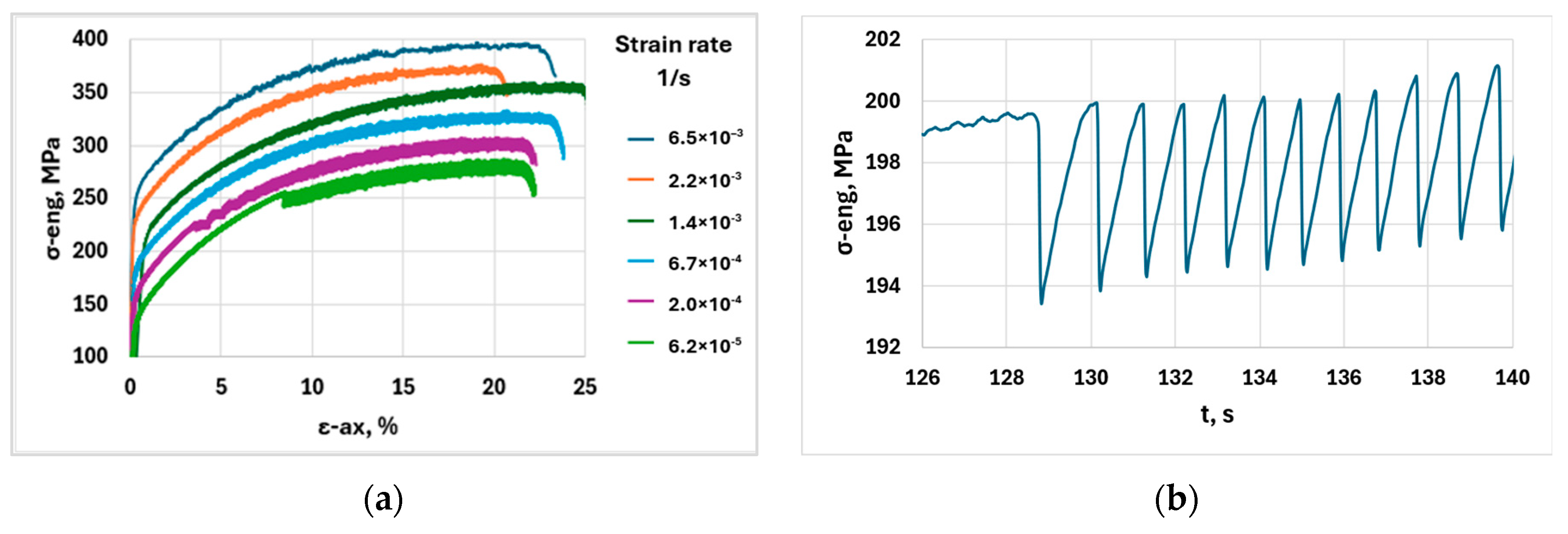
The tensile test curves of the AlMg4.5 sheets are shown in Figure 2a, which also shows the strain rate dependence of the results. Note that for illustrative purposes, each curve is shifted up. The lowest curve (6.2 × 10⁻⁵) is displayed with its original values, the others are shifted up by 25–50–75–100–125 MPa, respectively. Figure 2b shows an enlarged portion of a tensile test curve, showing the appearance of the critical strain (εcr) and the subsequent stress serrations.
The strength and formability characteristics determined by the tensile test are given in Table 1. In the case of the AlMg4.5 sheet, the strain rate does not significantly affect the value of any of the parameters.

4. Discussion

4.1. Analysis of the Parameters of the Reference Function

A detailed evaluation of the serrations was performed for the previously mentioned engineering strains of 4–8–12–16–20% directly from the tensile test curve as shown in Figure 1a. Waiting times are shown in Figure 3a for the five lower strain rates. The waiting time data of the given strain rate is defined as the average of the measurement points shown in the figure, which depends on the actual engineering strain. These averages are included in Table 2. Figure 3a shows that the waiting time increases slightly with strain, and the waiting time is higher at lower speeds. Figure 3b illustrates the decay times; these values are almost constant as a function of engineering strain.
Based on the study of stress serrations, it appeared that the number of points that can be considered in the Savitzky–Golay smoothing is optimal for the studied strain rates if the data points considered for the smoothing corresponds to the time of at least eight serrations. Thus, the window size, i.e., the number of points p, can be determined by the formula p = 8/Δt/fave, where Δt is the time between sampling, and fave is the average frequency of the stress serrations experienced at the given strain rate. The sampling time for each measurement was Δt = 0.02 s, and the average frequency of the stress serrations changed with strain rate.
The stress serration frequencies (fave) for the studied strain rates and the number of smoothing points (p) determined from them are shown in Table 2. However, when examining such a wide range of strain rates, considerations must also be made regarding the minimum sampling rate (fmin) and the time between sampling (Δtmin). The average frequency indicated in Table 2 does not provide correct information for this purpose, because the waiting and decay times are significantly different, and their dynamics are not the same (see Figure 1a). As a minimum condition, at least three points should determine the drop line of the engineering stress–time curve, i.e., there should be at least two sampling times for time to elapse between the positive and negative peaks. Therefore, the minimum sampling rate must be at least fmin = 2/td. The last column of Table 2 shows these values. During serration analysis, the number of window points (p) was used for SG smoothing. The fmin is only a suggestion for defining the minimum sample frequency. It should be noted that at higher strain rates, this results in low resolution in the calculation of td, so it is more justified to use higher sampling rates.
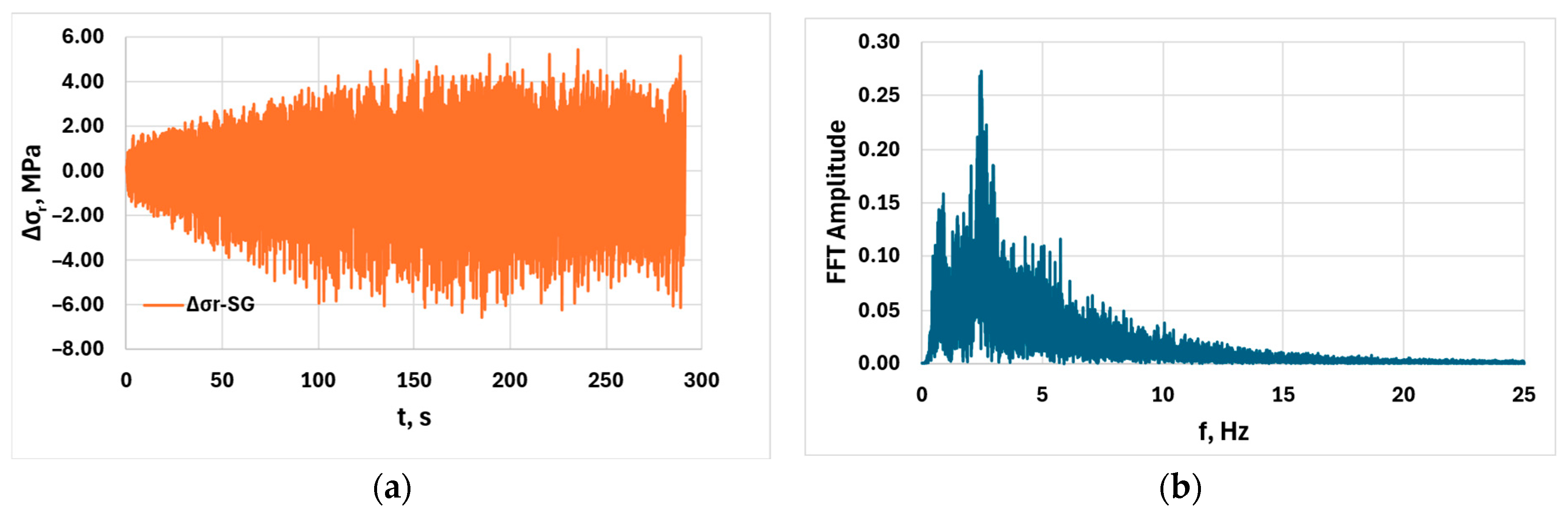
Figure 4a illustrates the amplitude of stress serrations relative to the reference function for the strain rate of 6.7 × 10⁻⁴ s−1. The figure shows that the positive and negative stress peaks increase to approximately 200 s depending on time, and then decrease slightly after the saturation phase. The formula according to Equation (1) is suitable for the characterization of stress peaks, which is the average difference between ten positive and negative peaks.
Δ σ 10 = [ i = 1 10 Δ σ i m a x i = 1 10 Δ σ i m i n ] / 10
The other frequently analyzed factor is the amplitude–frequency function obtained by Fast Fourier Transform (FFT), which can be calculated from the stress amplitude–time (Δσr-t) points. Figure 4b shows this FFT spectrum, with a amplitude peak around 2.5 Hz, after which the function decreases steadily.

4.2. Effect of Strain Rate on PLC Characteristics

By direct analysis of the tensile test curves, strain rate dependence of the critical plastic strain and serration amplitude was evaluated, which were in coherence with the results reported in [6,7]. Figure 5 shows the average waiting and decay times from Table 2 as a function of strain rate.
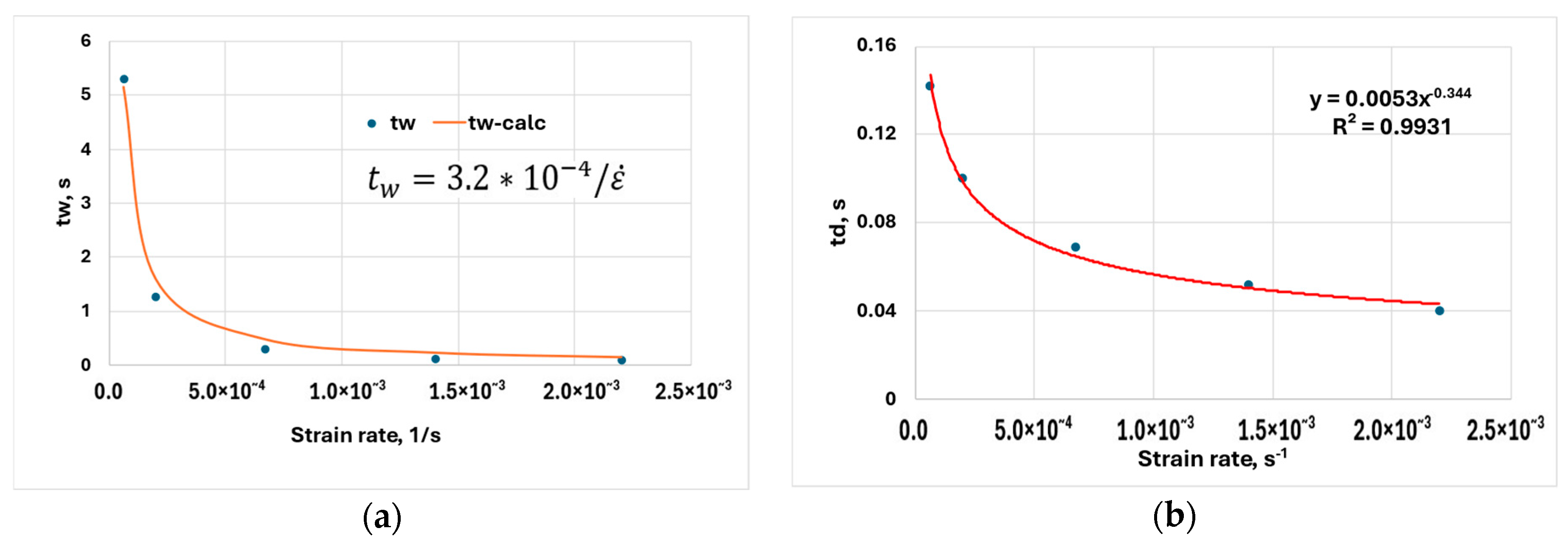
Visual analysis of the tensile test curves showed that at the strain rate 2.2 × 10⁻³ s−1, stress serrations are already of B + C-type, and at lower rates, C-type stress serration dominates. Both strain rate functions show a decreasing trend in accordance with the literature. The waiting time according to Figure 5a follows the previously mentioned hyperbolic formula ( t w = Ω / ε ˙ ) published in [11,13]. The value of Ω is determined from the measurement data t w = 3.2 × 10 4 / ε ˙ . This result is in coherence with the results reported in [13] and is in good agreement with the approximation proposed by [12]. If Ω = b ρ f / 3 and ρf = 1 × 10¹³ m−2, then Ω = 2.98 × 10⁻⁴, which is near to the value obtained from the measurement results. It should be noted that since the value of Ω depends on the number of mobile and forest dislocations, and the dislocation density increases with strain, Ω also increases. In the calculations, instead of tw values increasing with engineering strain, their average is used; so the dislocation density, and thus the value of Ω must be considered as an average value. Furthermore, comparing these numerical tw values with the measurement data published in [15], there is also a good agreement, so the measurement results can be verified by the literature sources. However, the decay time td could not be properly approximated by a hyperbolic function; a power function, shown in Figure 5b, gave a better approximation.
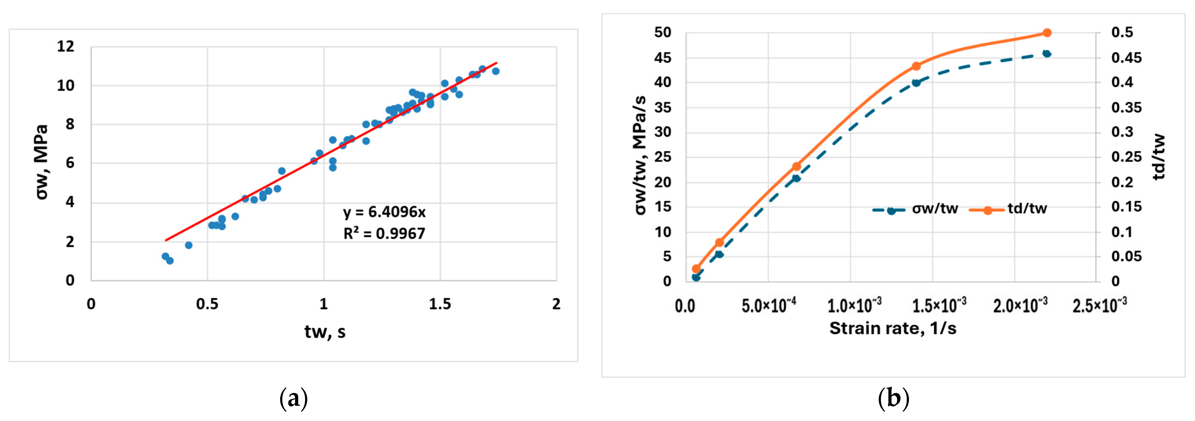
Further observations can also be made about the relationship between waiting times and the associated σw stress increases. Figure 6a shows the relationship between waiting time and stress increase for a given strain rate and strain interval. The values of stress serrations also show that the points are densified in two parts of the coordinate system: C-type serrations dominate in the range between 6 and 12 MPa, but there are also serrations of lower amplitude (2–5 MPa), which refer to the occasional B-type serrations. The relationship is linear with a good approximation, so the average rate of stress increase (σw/tw) can be derived from the slope of the line, which is essentially the derivative of stress by time (MPa/s). Figure 6b shows that this slope increases with strain rate. However, the same figure shows a relationship that has not been studied so far: the ratio of td/tw. This suggests that the decay time shows an extremely small ratio corresponding to the waiting time at low strain rates, i.e., this is where the C-type serration pattern occurs, where the relatively slow build-up of stress is followed by a rapid drop from the upper stress peak (see Figure 1a). As the curve moves towards higher strain rates, this ratio increases rapidly, which means that within the sawtooth-like serration, the waiting and decay times begin to equalize, i.e., they move towards type-B serrations. It is important to note that the td/tw and σw/tw functions are similar, so these relationships may be suitable for detecting the transition from type-B + C to type-C. Comparing the td/tw ratio with the engineering stress–strain diagrams, it can be stated that in the 6.2 × 10⁻⁵ and 6.7 × 10⁻⁴ s−1 ranges, C-type serrations dominate; at the strain rate of 1.4×10⁻³, B-type serrations appear with a higher probability; at strain rate 2.2 × 10⁻³ s−1, type-B is dominant, but type-A jumps also occur; at 6.5 × 10⁻³ s−1, A +B-type serrations are clearly present. This observation is reflected in the diagrams in Figure 6b.
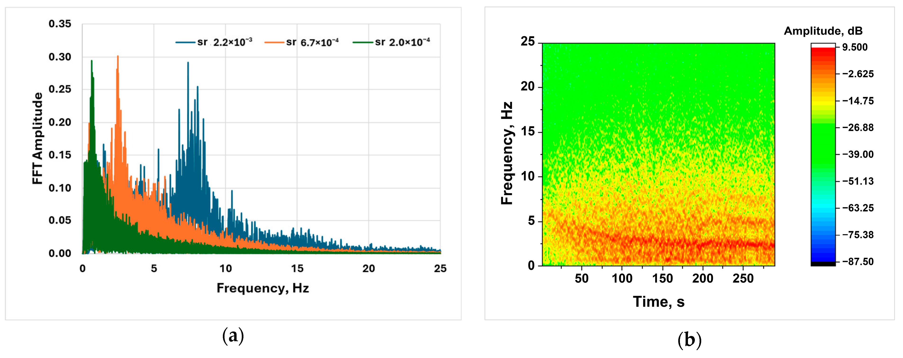
The relationship between the frequency spectrum and the strain rate is shown in Figure 7a, based on the FFT analysis. It is clearly seen from the diagram that the lowest strain rate is associated with the first peak at the lowest frequency, and as the strain rate increases, the peak frequency shifts towards higher values. This can be explained by the fact that as the strain rate increases, the waiting time decreases, so the frequency increases. Figure 7b shows the amplitude distribution of the Short-Time Fourier Transform for the strain rate of 6.7 × 10⁻⁴ s−1, on which the maximum amplitudes are condensed around 2.5 Hz, similar to the FFT spectrum, and the amplitude distribution stabilizes after the initial decrease as a function of time. These significantly different FFT results also prove that it is important to pay special attention to frequency analysis of the PLC effect.

5. Summary

As a summary of the strain rate analysis performed on the AlMg4.5 alloy, it can be stated that the PLC stress serrations of these sheets in the examined strain rate range can be analyzed by optimal selection of the reference function parameters. However, to achieve this, it is necessary that the size of the smoothing window must always be adjusted to the average serration time and frequency of the process to be examined. The stress amplitude and time parameters of serrations can be determined by evaluating the engineering stress–time coordinates of the peaks. The results confirmed the previous assumption that the waiting time is hyperbolic with the strain rate. As a new result, it could be shown that the quotient of the decay and waiting time forms a curve with a decreasing slope after an initial faster rise, and the same can be stated for the derivative of the stress increase. These relationships are suitable for analyzing the transition of type-B serrations to type-C, in full harmony with the stress serrations observed in the tensile test curves.

Author Contributions

I.C.: conceptualization, supervision, and writing—review and editing. D.H.: investigation, data curation, methodology, writing—original draft preparation, visualization. All authors have read and agreed to the published version of the manuscript.

Funding

The research presented in this paper was funded by the National Security Subprogram at the Széchenyi István University (TKP2021-NVA-23).

Institutional Review Board Statement

Not applicable.

Informed Consent Statement

Not applicable.

Data Availability Statement

Dataset available on request from the authors.

Conflicts of Interest

The author declares no conflicts of interest.

References

  1. Portevin, A.; Le Chatelier, F. On a phenomenon observed during the tensile testing of alloys undergoing transformation. C. R. Acad. Sci. Paris 1923, 176, 507–510. (In French) [Google Scholar]
  2. Saad, G.; Fayek, S.A.; Fawzy, A.; Soliman, H.N.; Nassr, E. Serrated flow and work hardening characteristics of Al-5356 alloy. J. Alloys Compd. 2010, 502, 139–146. [Google Scholar] [CrossRef]
  3. Zhang, Y.; Liu, J.P.; Chen, S.Y.; Xie, X.; Liaw, P.K.; Dahmen, K.A.; Qiao, J.W.; Wang, Y.L. Serration and noise behaviors in materials. Prog. Mater. Sci. 2017, 90, 358–460. [Google Scholar] [CrossRef]
  4. Tian, N.; Wang, G.; Zhou, Y.; Liu, K.; Zhao, G.; Zuo, L. Study of the Portevin-Le Chatelier (PLC) characteristics of a 5083 aluminum alloy sheet in two heat treatment states. Materials 2018, 11, 1533. [Google Scholar] [CrossRef] [PubMed]
  5. Yuan, Z.; Li, F.; He, M. Fast Fourier transform on analysis of Portevin-Le Chatelier effect in Al 5052. Mater. Sci. Eng. A 2011, 530, 389–395. [Google Scholar] [CrossRef]
  6. Ait-Amokhtar, H.; Fressengeas, H.; Bouabdallah, K. On the effects of the Mg content on the critical strain for the jerky flow of Al-Mg alloys. Mater. Sci. Eng. A 2015, 636, 180–186. [Google Scholar] [CrossRef]
  7. McCormick, P.G. Effect of grain size on serrated yielding in an Al-Mg-Si alloy. Philos. Mag. A 1971, 23, 949–956. [Google Scholar] [CrossRef]
  8. Kovács, Z.; Lendvai, J.; Vörös, G. Localized deformation bands in Portevin–Le Chatelier plastic instabilities at a constant stress rate. Mater. Sci. Eng. A 2000, 279, 179–184. [Google Scholar] [CrossRef]
  9. Reed, J.M.; Walter, M.E. Observations of serration characteristics and acoustic emission during serrated flow of an Al–Mg alloy. Mater. Sci. Eng. A 2003, 359, 1–10. [Google Scholar] [CrossRef]
  10. Wen, W.; Morris, J.G. The effect of cold rolling and annealing on the serrated yielding phenomenon of AA5182 aluminum alloy. Mater. Sci. Eng. A 2004, 373, 204–216. [Google Scholar] [CrossRef]
  11. Gopinath, K.; Gogia, A.K.; Kamat, S.V.; Ramamurty, U. Dynamic strain ageing in Ni-base superalloy 720Li. Acta Mater. 2009, 57, 1243–1253. [Google Scholar] [CrossRef]
  12. Saadat, Z.; Moghanaki, S.K.; Kazeminezhad, M.; Goodarzi, M.; Afjeh, S.M.B.G. Effect of two steps annealing on the microstructure and dynamic strain aging behavior of Al-6Mg alloy. Mater. Sci. Eng. A 2020, 798, 140097. [Google Scholar] [CrossRef]
  13. Kubin, L.P.; Estrin, Y. Evolution of dislocation densities and the critical conditions for the Portevin-Le Chatelier effect. Acta Metall. Mater. 1990, 38, 697–708. [Google Scholar] [CrossRef]
  14. Lee, S.Y.; Chettri, S.; Sarmah, R.; Takushima, C.; Hamada, J.; Nakada, N. Serrated flow accompanied with dynamic type transition of the Portevin–Le Chatelier effect in austenitic stainless steel. J. Mater. Sci. Technol. 2023, 133, 154–164. [Google Scholar] [CrossRef]
  15. Ait-Amokhtar, H.; Boudrahem, S.; Fressengeas, C. Spatiotemporal aspects of jerky flow in Al–Mg alloys, in relation with the Mg content. Scr. Mater. 2006, 54, 2113–2118. [Google Scholar] [CrossRef]
Figure 1. Interpretation of serration parameters on a characteristic engineering stress–time diagram detail (2 × 10⁻⁴ s−1): (a) definition of stress and time parameters; (b) characteristic detail of stress amplitude–time diagram (difference between measured engineering stress and reference function).
Engproc 113 00025 g001
Figure 2. Engineering stress–engineering strain curves of samples: (a) influence of strain rate; (b) occurrence of critical strain (2 × 10⁻⁴ s−1).
Engproc 113 00025 g002
Figure 3. Waiting and decay time relations: (a) waiting time–engineering strain; (b) decay time–engineering strain.
Engproc 113 00025 g003
Figure 4. Serration amplitude and Fourier spectrum (6.7 × 10⁻⁴ s−1): (a) stress–time function; (b) FFT spectrum.
Engproc 113 00025 g004
Figure 5. Strain rate dependence on the waiting and decay time: (a) waiting time; (b) decay time.
Engproc 113 00025 g005
Figure 6. Analysis of the stress and time parameters: (a) relation between waiting time and stress jump (2 × 10⁻⁴ s−1/12%); (b) stress increase gradient and td/tw ratio as function of strain rate.
Engproc 113 00025 g006
Figure 7. Strain rate dependence of the serration frequency: (a) FFT analysis; (b) Short-Time Fourier Transform of serrations (6.7 × 10⁻⁴ s−1).
Engproc 113 00025 g007
Table 1. Results of the tensile test.
ε   ˙ s−1Rp0.2;
MPa
Rm;
MPa
Ag;
%
At;
%
nr
6.5 × 10−313226920.123.00.310.81
2.2 × 10−313126918.221.20.310.83
1.4 × 10−314128121.825.20.310.78
6.7 × 10−414028321.324.10.310.84
2.0 × 10−413528222.122.20.320.85
6.2 × 10−513626722.122.30.330.81
Abbreviations: Rp0.2—yield stress at 0.2% strain; Rm—ultimate tensile strength; Ag—uniform engineering strain at maximum load; At—fracture strain; n—hardening exponent, calculated between 4 and 6% engineering strain using the Hollomon equation; r—normal anisotropy, evaluated between 8 and 12% engineering strain.
Table 2. Evaluated time and calculated smoothing parameters.
ε   ˙ s−1tw, std, st = tw + td, sfave, Hzpfmin, Hz
2.2 × 10−30.0800.0400.1208.3334950
1.4 × 10−30.1200.0520.1725.8146938
6.7 × 10−40.2970.0690.3662.73214729
2.0 × 10−41.2580.1001.4030.71356120
6.2 × 10−55.2940.1425.4360.184217314
Disclaimer/Publisher’s Note: The statements, opinions and data contained in all publications are solely those of the individual author(s) and contributor(s) and not of MDPI and/or the editor(s). MDPI and/or the editor(s) disclaim responsibility for any injury to people or property resulting from any ideas, methods, instructions or products referred to in the content.