Proceeding Paper

Experimental and Numerical Analysis of Hybrid Silica Sand–Basalt Rock Thermal Energy Storage for Enhanced Heat Retention and Discharge Control †

1
Department of Mechanical Engineering, Institute of Space Technology, Islamabad 44000, Pakistan
2
Department of Mechanical Engineering, National University of Science and Technology EME, Islamabad 44000, Pakistan
*
Author to whom correspondence should be addressed.
Presented at the 5th International Conference on Advances in Mechanical Engineering (ICAME-25), Islamabad, Pakistan, 26 August 2025.
Eng. Proc. 2025, 111(1), 6; https://doi.org/10.3390/engproc2025111006
Published: 15 October 2025

Abstract

In order to guarantee energy sustainability, effective thermal energy storage (TES) systems are required due to the volatile nature of renewable energy sources. In order to optimize energy storage capacity and reduce thermal losses, this study addresses a hybrid TES system that combines basalt rocks and silica sand. Using ANSYS, a computational transient thermal analysis was conducted to compare conduction and convection heat transfer modes, revealing convection as the more effective mechanism. Six sand–rock mixtures were tested experimentally; the 70% sand and 30% rock combination produced the highest temperature increase (52.38 °C), the highest heat storage capacity (3.21 ± 0.19 MJ), alongside an efficiency of 80.5%. This hybrid system had a very low discharge rate (0.24 ± 0.036 MJ lost in one hour), outlining its potential for integration with renewable energy. The results show that hybrid sand–rock TES systems are a cheap and green alternative to solutions that rely on fossil fuels. They can be used for large-scale energy storage.

1. Introduction

The search for effective and feasible energy systems has accelerated due to the need to reduce greenhouse gas emissions and the growing global request for energy. The capacity of thermal energy storage (TES) to store excess heat for later use has made it one of the most popular promising strategies, improving both the reliability and effectiveness of renewable energy systems. The use of natural solid materials like rocks and sand for sensible heat storage is notable for its affordability, ease of use, and advantageous thermophysical traits, such as high heat capacity, thermal conductivity, and chemical stability at high temperatures.
For TES applications, sand has been thoroughly researched. After evaluating sands from the Arabian desert, Radwan et al. [1] found that pure quartzose sand, which contains more than 95% quartz, had unique thermal behavior. Chung and Chen [2] further enhanced the performance of sand by coating it with black spinel nanoparticles. Sand–bentonite mixtures used as backfilling materials drastically improved the energy efficiency of ground–air heat exchangers, especially in wet conditions, as shown by Coletti et al. [3].
By thermally charging silica sand using a hybrid system of solar, wind, and electric heating, Jemmal et al. [4] were able to store up to 25,000 MWh of energy while lowering CO2 emissions. According to Tetteh et al. [5], adding brass and aluminum chips to sand improved its effective thermal conductivity. El Alami et al. [6] verified that the quantity and size of quartz crystals in granitoid rocks affect their thermal conductivity. Using paraffin wax, Edhari et al. [7] created a composite TES unit that combined basalt, paraffin wax, and water to achieve water outlet temperatures above 50 °C.
Basalt rocks have also been studied as efficient TES media. According to Schlipf et al. [8], basalt has a high specific thermal capacity of 1028 J/kg·°C, which makes it fit for long-term storage. Crushed basalt can be used in place of molten salts and maintain its strength over 150 thermal cycles, according to research by Disha and Forsberg [9]. In contrast to limestone, basalt retained its structure when Hrifech et al. [10] examined the behavior of Moroccan rocks at temperatures as high as 650 °C. Barbhuiya et al. [11] provided additional support for these findings by demonstrating that the use of concrete as a storage medium improves the performance of heat transfer in TES systems. Dincer et al. [12] emphasized the significance of proposing stones, sand, and gravel as feasible TES candidates. They observed that stones provide a quicker thermal response during charging and discharging. Volcanic ash was suggested by Kothari et al. [13] as a stable, corrosion-resistant substitute for molten salt at elevated temperatures. By incorporating rock-bed TES into a coal-fired power plant, Serrano et al. [14] showed a 34.9% efficiency gain. In contrast, Knobloch et al. [15] found that in a 1 MWh rock-bed TES system run over 249 cycles, system-level degradation was more important than material degradation.
In their investigation of the mechanical changes in carbonate and sandstone rocks under heat stress, Jaber et al. [16] found that thermal cracking caused increased permeability above 85 °C. After comparing various TES techniques, Sarbu and Sebarchievici [17] came to the conclusion that thermochemical storage provides the best efficiency. In TES systems, Maldonado et al. [18] discovered that heat pipes perform better than metal rods in terms of pumping power and energy efficiency. Hosseini et al. [19] improved water heater efficiency by utilizing inclined flat aluminum fins at a 20° angle in place of traditional shell-and-tube exchangers, while Permatasari et al. [20] showed superior COP using cold water as the heat transfer fluid at 1.661 kg/s.
The performance of rocks or sand alone in TES has been extensively investigated, but hybrid sand–rock systems have received less attention. In order to produce an ideal, sustainable solution, such systems might take advantage of the quick thermal response of sand and the high thermal retention of rocks. Additionally, a comparative analysis of TES designs based on conduction and convection is lacking. In order to close this gap, this study explores a hybrid sand–rock TES setup using experimental testing and numerical simulations to identify the best configuration for optimizing energy storage while minimizing losses.

2. Problem Formulation

In order to evaluate the thermal performance of different sand–rock mixtures, two distinct heat transfer configurations—namely conduction and convection—were employed and thoroughly screened. This study investigates a hybrid thermal energy storage (TES) system. Two different CAD models were created to represent each mode. Twelve circular aluminum fins, each 10 cm long and 3 cm in diameter, were set into a 45 cm × 40 cm × 15 cm steel container for the conduction-based model shown in Figure 1. An aluminum piping system with an equivalent surface area was built to guarantee a constant heat input using the convection model, which was based on the surface area of the fins and base from the conduction setup.
The height of the convection container was raised from 15 cm to 16.2 cm in order to account for the volume displaced by the internal piping and maintain a constant internal volume for the storage medium in both models. To ascertain the temperature distribution and general thermal behavior, both models were subsequently put through transient thermal simulations with Ansys 2022. The optimal heat transfer configuration was chosen for experimental validation based on the simulation results. The chosen model was then used to test six different material compositions with varying sand-to-rock ratios in order to evaluate energy storage and discharge properties.

3. Methodology

A comprehensive methodology was used to investigate the suitable mode of heat transfer for thermal storage in sand and rocks. By keeping the surface area constant, two different 3D CAD models were created in SOLIDWORKS 2020 software.

3.1. CAD Modeling

Three-dimensional CAD models were created with a constant surface area to identify the suitable mode of heat transfer for storing thermal energy.

3.1.1. Conduction

For the conduction case, 12 circular fins were placed in the heat exchanger. The dimensions of the heat exchanger are mentioned in Table 1 and the CAD model is shown in Figure 1 below.

3.1.2. Convection

For the convection case, the heat exchanger design was modified such that the total surface area of the fins was calculated, and then a piping system of the same surface area was placed in it. In order to keep the volume of mixture constant, we increase the height of the heat exchanger. The following calculations were carried out to create the convection CAD model.
Area of fin = 94.2 cm2
As there are 12 fins so, total area of 12 fins becomes 1130.4 cm2
Base area of box = 45 × 40 =1800 cm2
Total surface area = 1800 cm2 + 1130 cm2 =2930 cm2
Vol. of box = 27,000 cm3
Vol. of fin = 85 cm3
Vol. of mixture = 26,915 cm3
Thus, in order to draw a comparison between both CAD models, we have kept the volume of the mixture constant:
2930 = 3.14 × 3 × L
L = 320 cm
Vol. of piping system = 2245 cm3
Therefore, in order to keep the volume of the mixture constant, we increased the height of the box to 16.2 cm.
The new dimensions of the heat exchanger for the convection case are shown in Table 2. The CAD model design of the piping system and the convection configurations are shown in Figure 2, respectively.

3.2. Mathematical Modeling

ANSYS 2022 Workbench was used to conduct a transient thermal analysis in order to model sand–rock TES. The basic principles of thermodynamics were used to model the fundamental heat transfer mechanisms for conduction and convection. The unsteady heat conduction formulation was solved in order to predict the temperature dispersion inside the storage medium. The fundamental heat conduction equation is as follows:
t ( ρ c p T ) =   ( k T )
The temporal variation in temperature within a solid realm are taken into consideration by this equation. We used convective boundary conditions on the inside walls of the aluminum pipe for the convection model.

Thermal Energy Storage Calculation

Heat storage in sand and rocks separately is calculated by the relation given below.
Q = m × cp × T
Heat storage for hybrid mixtures of rocks and sand is computed using the relationship below. In hybrid samples, where both materials contribute proportionately to the storage capacity, this equation enables precise energy accounting.
Q = mT × [ C ps   ( m s m T ) + C pr   ( m r m T ) ] × T
where,
  • mT = Total mass of mixture (kg)
  • cps, cpr = Specific heat capacity of sand and rocks (J/kg·K)
  • T = Rise in temperature (°C)
  • ms, mr = Mass of silica sand and basalt rocks, respectively.

4. Numerical Study

The thermal evaluation of these two CAD models was accessed using transient thermal analysis in ANSYS 2022. This involved visualizing the temperature contours in order to check which mode of heat transfer produced a more rapid rise in temperature. After that, a complete prototype was then tested in order to access how effective the heat storage was.

4.1. Mesh Independence

A mesh independence study was conducted to reduce the cost associated with computing the simulation and ensure accuracy. Six different meshes were obtained with cell numbers of 15.7, 23.9, 35.4, 56.7, 76.5, and 98.6 thousand, respectively. Table 3 shows the average rise in temperature in the system for all six grid sizes.

4.2. Mesh Sizing, Solver Settings, and Boundary Conditions

The accuracy and stability of the simulation are significantly affected by mesh quality. The computational mesh created in this analysis was composed of tetrahedral cells. Thus, simulations were performed with an element size of 0.009, corresponding to 76.5 thousand elements, as shown in Figure 3. Table 4, shows the investigation parameters of silica sand and basalt rocks which were used in the simulations.
Heat transfer dynamics in both models were examined through the use of ANSYS 2022 Workbench in transient thermal simulations. The solver was setup for transient analysis with a fixed time step size of 30 s and a total simulation time of 7200 s. To guarantee numerical accuracy and stability, a second-order backward Euler implicit scheme was used. Material properties are listed in Table 4. A constant temperature boundary condition of 65 °C was used to apply heat to the internal surface of the aluminum piping in the convection model and to the bottom wall and fins in the conduction model. In order to replicate optimal insulation, external surfaces were deemed adiabatic. As laid out in Section 4.1, a study of six grid sizes was used to verify mesh independence.

4.3. Simulations

In order to choose the most accurate mode of heat transfer for our project, a temperature of 65 °C was applied at the base and bottom of the fins and box in the case of conduction. For convection, the same temperature was assigned to the piping system of the same surface area used in the conduction case, while the walls were kept insulated in both cases. The temperature contours of both modes of both heat exchanger models on which transient thermal analysis was performed are shown in Figure 4. Among the two modes of heat transfer, the best mode was selected based on the highest average rise in temperature with respect to time. The average rise in temperature in the conduction case was 25.13 °C, while it was 49 °C for convection. The combined average temperature of both models is shown in Figure 5. The highest rise in temperature was obtained in the convection case. Therefore, we proceeded with the convection mode of heat transfer for experimentation.

5. Experimental Setup

The setup consists of a steel box with an aluminum pipe whose dimensions are given in Table 2. The steel box is insulated with a 2 cm polystyrene sheet, and six K-type thermocouples are placed for temperature readings. Thermocouples of the K type were utilized to track the temperature, and a digital balance was used for mass measurement. Thermocouples have an accuracy of ±1.5 °C or ±0.4% of the reading, while the digital balance has an accuracy of ±1%. An unsteady-state heat transfer apparatus was used to heat water to a maximum of 70 °C, operated at an average temperature of 65 °C. Hot water was pumped and allowed to flow through the pipe in a closed-loop system for the transmission of thermal energy in the storage medium. The experimental setup is shown in Figure 6.
In order to check the thermal energy storage capacity of silica sand and basalt rock, charging and discharging of six combinations of storage materials were tested. Samples were heated until steady-state temperature was achieved. Samples of 100% silica sand, 100% basalt rocks, 30% silica sand and 70% basalt rocks, 50% silica sand and 50% basalt rocks, 65% silica sand and 35% basalt rocks, and 70% silica sand and 30% basalt rocks are shown in Figure 7, and their proportions are listed in Table 5, respectively.

6. Results and Discussion

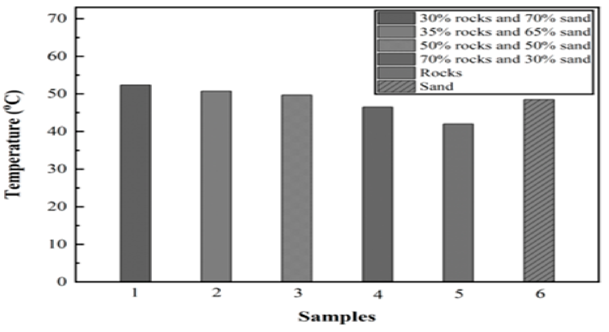
In this study, six different experiments were carried out to test experimentally which of these six samples had the highest heat storage ability as well as the lowest heat dissipation rate. Temperature variations in all six samples are shown in Figure 8.

6.1. Experiment 01: 100% Silica Sand

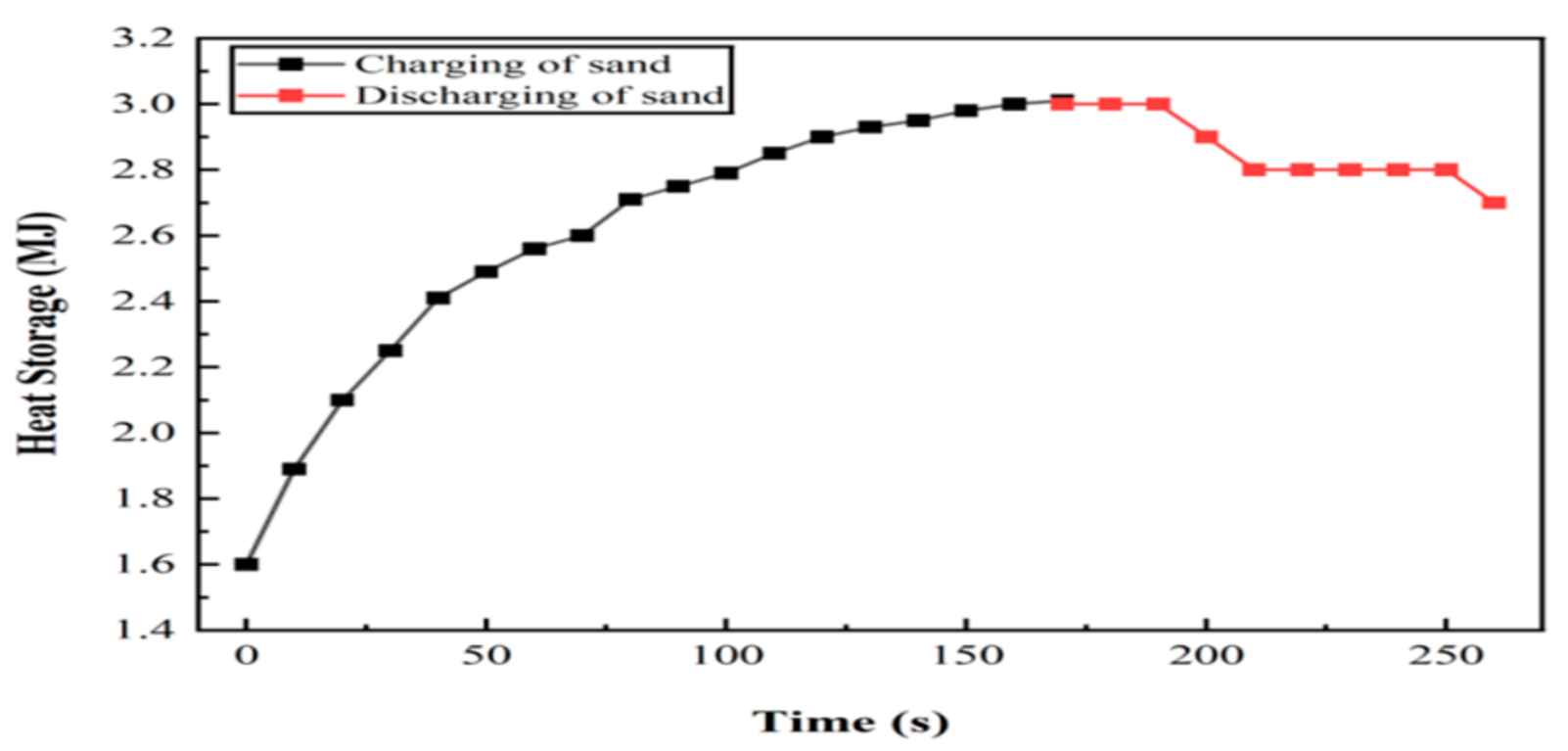
The first experiment was conducted on silica sand. It was observed that silica sand reached its steady-state conditions at a 48.5 °C rise in temperature, with 2.8 ± 0.17 MJ of thermal energy in it. During discharge, 0.28 ± 0.041 MJ was released in 1 h, while 2.54 ± 0.175 MJ of thermal energy remained in the system. The graph of heat distribution is shown in Figure 9.

6.2. Experiment 02: 100% Basalt Rocks

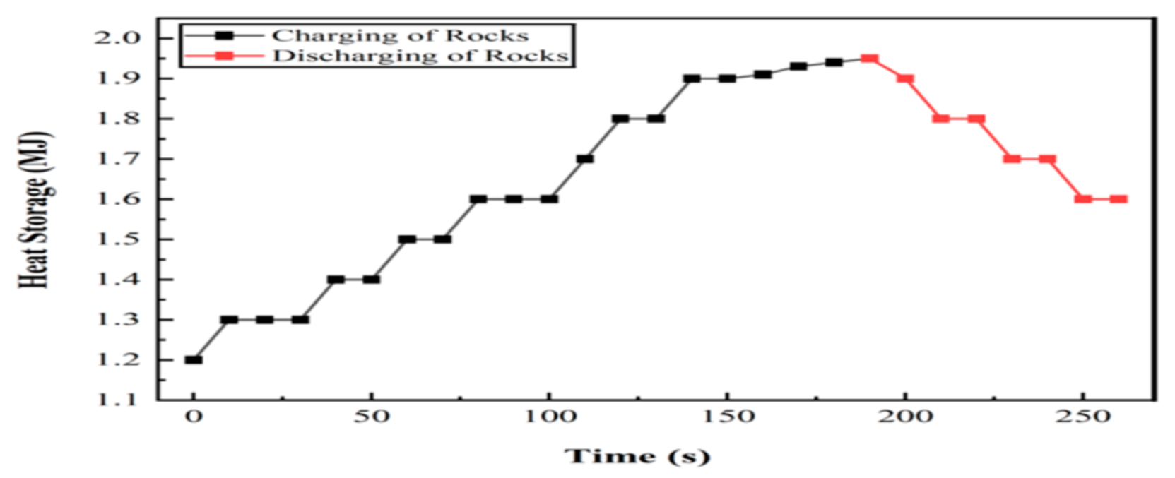
The second experiment was conducted on basalt rocks. Basalt rocks reached its steady-state conditions at a 42 °C rise in temperature, with 1.9 ± 0.12 MJ of heat storage. However, it discharged 0.3 ± 0.043 MJ of thermal energy in 1 h, while 1.6 ± 0.128 MJ of thermal energy remained in the system. The graph of heat distribution is shown in Figure 10.
The temperature of the sand sample rose by 48.5 °C in the experimental test and 49 °C in the numerical analysis, while for rocks it was 42 °C in the experimental test and 42.05 °C in the numerical analysis. This high agreement confirms the simulation’s accuracy and the dependability of our integrated approach, giving us a strong basis for assessing changes in the sand–rock ratio.

6.3. Experiment 03: 30% Silica Sand and 70% Basalt Rocks

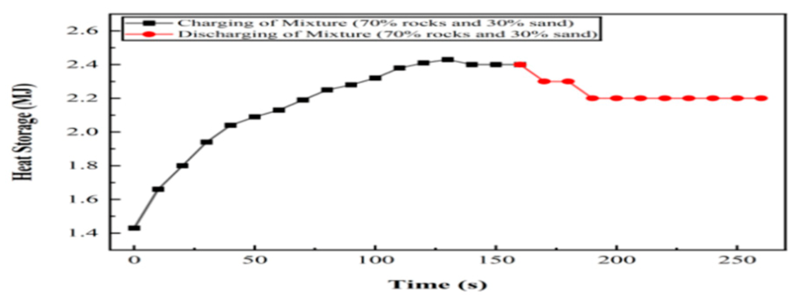
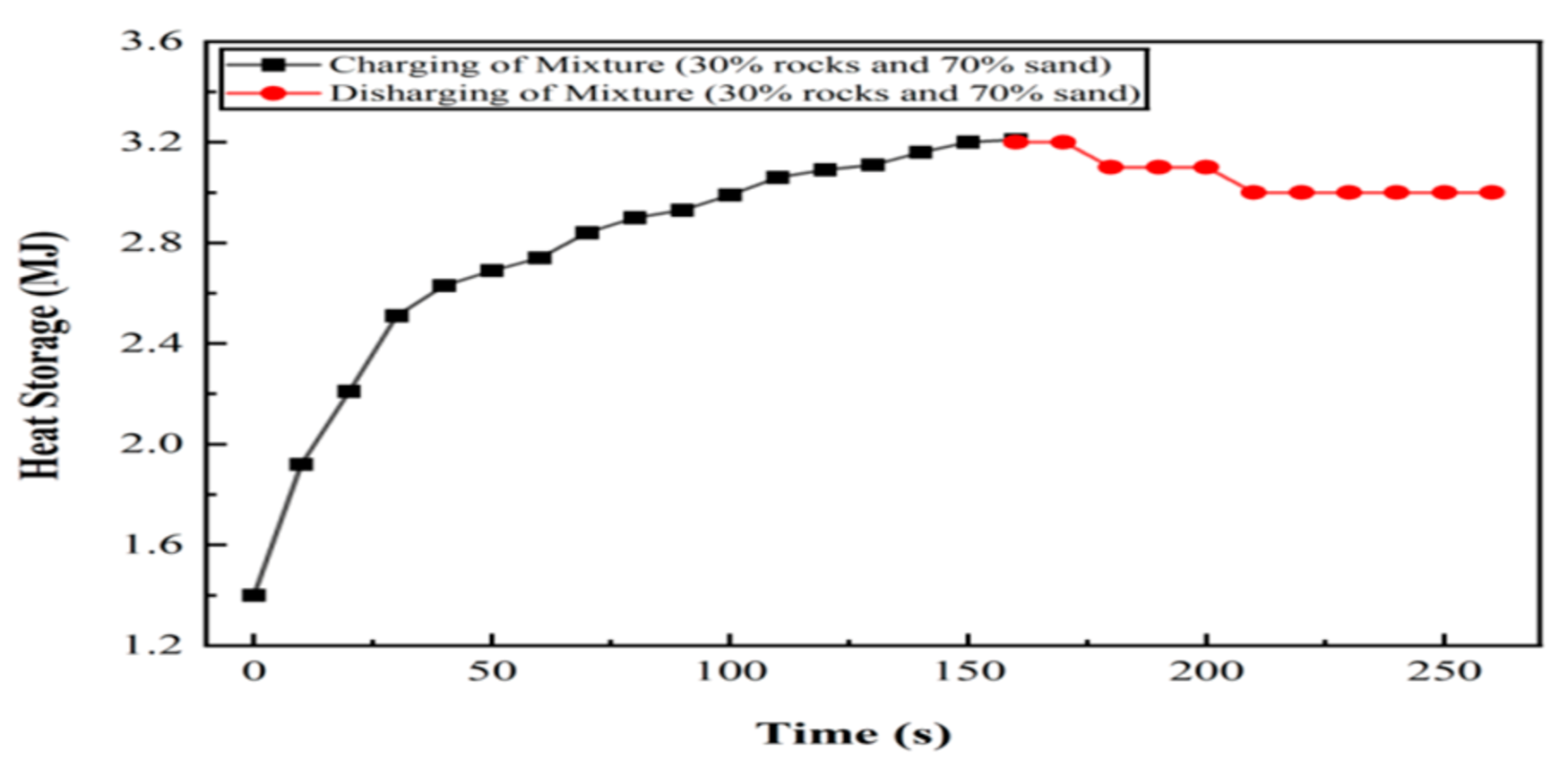
The third experiment was conducted with 70% rocks and 30% sand. This sample reached its steady-state conditions at a 46.5 °C rise in temperature, with a heat storage of 2.4 ± 0.14 MJ. However, it discharged 0.27 ± 0.040 MJ of thermal energy in 1 h, while 2.2 ± 0.145 MJ of thermal energy remained in the system. The graph of heat distribution is shown in Figure 11.

6.4. Experiment 04: 50% Silica Sand and 50% Basalt Rocks

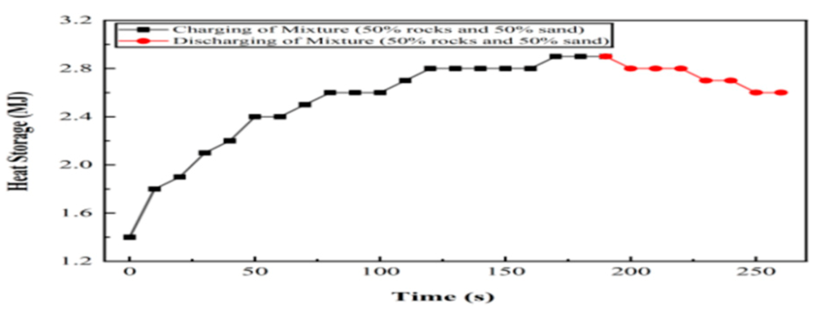
The fourth experiment was conducted with a combination of 50% of both sand and rocks. However, this sample reached its steady-state conditions at a 49.7 °C rise in temperature, with a heat storage of 2.9 ± 0.17 MJ. However, it discharged only 0.26 ± 0.039 MJ of thermal energy in 1 h, which was less than both sand and rocks individually, while 2.64 ± 0.174 MJ of thermal energy remained in our system. The graph of heat distribution is shown in Figure 12.

6.5. Experiment 05: 65% Silica Sand and 35% Basalt Rocks

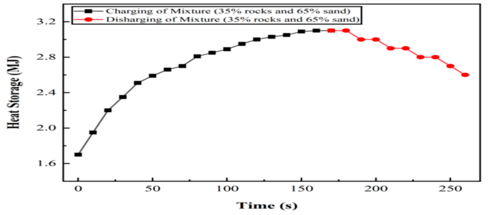
The fifth experiment was conducted on 65% sand and 35% rocks. This sample reached its steady-state conditions at a 50.7 °C rise in temperature, with a heat storage of 3.4 ± 0.18 MJ. However, it discharged 0.25 ± 0.038 MJ of thermal energy in 1 h, while 2.79 ± 0.184 MJ of thermal energy remained in the system. The graph of heat distribution is shown in Figure 13.

6.6. Experiment 06: 70% Silica Sand and 30% Basalt Rocks

The sixth experiment was conducted on 70% sand and 30% rocks. This sample reached its steady-state conditions at 52.38 °C, with a heat storage of 3.21 ± 0.19 MJ. However, it only discharged 0.24 ± 0.036 MJ of thermal energy after 1 h, while 2.97 ± 0.193 MJ remained in the system. The graph of heat distribution throughout the experiment is shown in Figure 14.
This sample was also tested for the production of hot water. By taking water at 24.1 °C from the pipe inlet, we obtained hot water at 42 °C at the pipe outlet. The combined effect of heat storage for all the six experiments is shown in Figure 15. The combined impact of material properties accounts for the observed trend: rocks, with higher heat capacity and conductivity, optimize thermal retention, while sand, which has a lower heat capacity but heats up more quickly, allows a higher rise in temperature. With the highest stored energy and the lowest discharge, the 70% sand–30% rock mixture strikes the ideal balance between allowing quick charging from the sand and minimizing thermal loss from the rock’s thermal inertia.

7. Conclusions

Thermal energy attracts industries requiring large amounts of energy such as power generation facilities. This study used a hybrid system to store the maximum amount of thermal energy. In order to reduce reliance on fossil fuels and promote sustainability, silica sand and basalt rocks were chosen as storage materials. Transient thermal analysis was performed on both CAD models in order to choose the mode of heat transfer that produced the most rapid rise in temperature, which ultimately led to the highest heat storage ability. Water was used as a heat transfer fluid, and six thermocouples were placed at different locations in the system to measure the temperature distributions. Six different experiments were conducted by changing the concentrations of silica sand and basalt rocks, as listed in Table 4. The sample containing 70% silica sand and 30% basalt rocks had the highest efficiency (80.5%). This sample also has a greater rise in temperature (49.7 °C) and higher heat storage ability (3.21 ± 0.19 MJ). It lost only 0.24 ± 0.036 MJ of thermal energy in one hour, which was very low as compared to other samples. Therefore, in the context of both charging and discharging, the sand–rock hybrid TES system is preferred.

Author Contributions

Conceptualization, M.I., Z.W., R.T., and H.A.; methodology, M.I. and M.A.; software, M.I. and Z.W.; validation, M.I., Z.W., and R.T.; formal analysis, M.I. and Z.W.; investigation, M.I. and Z.W.; resources, M.I. and R.T.; data curation, M.I. and Z.W.; writing—original draft, preparation, M.I.; writing—review and editing, M.A. and T.I.K.; visualization, M.A.; supervision, M.A.; project administration, M.A. All authors have read and agreed to the published version of the manuscript.

Funding

This research received no external funding.

Institutional Review Board Statement

Not Applicable.

Informed Consent Statement

Not Applicable.

Data Availability Statement

The raw data supporting the conclusions of this article will be made available by the authors upon request.

Acknowledgments

The authors express their appreciation to the Institute of Space Technology for its financial support and to the lab personnel and engineers for their significant assistance.

Conflicts of Interest

The authors declare no conflicts of interest.

Abbreviations

The following abbreviations are used in this manuscript:
TESThermal Energy Storage
CADComputer-Aided Design
COPCoefficient of Performance
3DThree-Dimensional
CO2Carbon Dioxide

References

  1. Radwan, O.A.; Humphrey, J.D.; Hakeem, A.S.; Zeama, M. Evaluating Properties of Arabian Desert Sands for Use in Solar Thermal Technologies. Sol. Energy Mater. Sol. Cells 2021, 231, 111335. [Google Scholar] [CrossRef]
  2. Chung, K.M.; Chen, R. Black Coating of Quartz Sand towards Low-Cost Solar-Absorbing and Thermal Energy Storage Material for Concentrating Solar Power. Sol. Energy 2023, 249, 98–106. [Google Scholar] [CrossRef]
  3. Agrawal, K.K.; Misra, R.; Das Agrawal, G. Improving the Thermal Performance of Ground Air Heat Exchanger System Using Sand-Bentonite (in Dry and Wet Condition) as Backfilling Material. Renew. Energy 2020, 146, 2008–2023. [Google Scholar] [CrossRef]
  4. Jemmal, Y.; Zari, N.; Asbik, M.; Maaroufi, M. Experimental Characterization and Thermal Performance Comparison of Six Moroccan Rocks Used as Filler Materials in a Packed Bed Storage System. J. Energy Storage 2020, 30, 101513. [Google Scholar] [CrossRef]
  5. Tetteh, S.; Juul, G.; Järvinen, M.; Santasalo-Aarnio, A. Improved Effective Thermal Conductivity of Sand Bed in Thermal Energy Storage Systems. J. Energy Storage 2024, 86, 111350. [Google Scholar] [CrossRef]
  6. El Alami, K.; Asbik, M.; Agalit, H. Identification of Natural Rocks as Storage Materials in Thermal Energy Storage (TES) System of Concentrated Solar Power (CSP) Plants—A Review. Sol. Energy Mater. Sol. Cells 2020, 217, 110599. [Google Scholar] [CrossRef]
  7. Al Edhari, A.J.; Ngo, C.C. Experimental Study of Thermal Energy Storage Using Natural Porous Media. In ASME International Mechanical Engineering Congress and Exposition; American Society of Mechanical Engineers: New York, NY, USA, 2017. [Google Scholar]
  8. Schlipf, D.; Schicktanz, P.; Maier, H.; Schneider, G. Using Sand and Other Small Grained Materials as Heat Storage Medium in a Packed Bed HTTESS. Energy Procedia 2015, 69, 1029–1038. [Google Scholar] [CrossRef]
  9. Bandyopadhyay, D.; Forsberg, C. Selecting Rock Types for Very-Low-Cost Crushed Rock Heat Storage Systems with Nitrate Salt Heat Transfer. J. Energy Storage 2023, 61, 106664. [Google Scholar] [CrossRef]
  10. Hrifech, S.; Agalit, H.; Jarni, A.; Mouguina, E.M.; Grosu, Y.; Faik, A.; Bennouna, E.G.; Mimet, A. Characterization of Natural Rocks as Filler Materials for Medium-Temperature Packed Bed Thermal Energy Storage System. J. Energy Storage 2020, 32, 101822. [Google Scholar] [CrossRef]
  11. Barbhuiya, S.; Das, B.B.; Idrees, M. Thermal Energy Storage in Concrete: A Comprehensive Review on Fundamentals, Technology and Sustainability. J. Build. Eng. 2023, 82, 108302. [Google Scholar] [CrossRef]
  12. Yapicioglu, A.; Dincer, I. A Newly Developed Renewable Energy Driven Multigeneration System with Hot Silica Sand Storage for Power, Hydrogen, Freshwater and Cooling Production. Energy Technol. Assess. 2023, 55, 102938. [Google Scholar] [CrossRef]
  13. Kothari, R.; La Seta, A.; Hemmingsen, C.S.; Desai, N.B.; Haglind, F. Numerical analysis of measures to minimize the thermal instability in high temperature packed-beds for thermal energy storage systems. J. Energy Storage 2024, 94, 112431. [Google Scholar] [CrossRef]
  14. Serrano, M.I.R.; Knobloch, K.; Giuliano, S.; Engelbrecht, K.; Hirsch, T. Retrofit of a Coal-Fired Power Plant with a Rock Bed Thermal Energy Storage. J. Energy Storage 2024, 75, 109238. [Google Scholar] [CrossRef]
  15. Knobloch, K.; Ulrich, T.; Bahl, C.; Engelbrecht, K. Degradation of a Rock Bed Thermal Energy Storage System. Appl. Therm. Eng. 2022, 214, 118823. [Google Scholar] [CrossRef]
  16. Jaber, H.; Maalouf, E.; Yehya, A.; Salah, M.K.; Bou-Hamdan, K.; Harb, M. The Effect of Temperature on the Mechanical and Hydraulic Properties of Sedimentary Rocks. Geoenergy Sci. Eng. 2024, 235, 212702. [Google Scholar] [CrossRef]
  17. Sarbu, I.; Sebarchievici, C. A Comprehensive Review of Thermal Energy Storage. Sustainability 2018, 10, 191. [Google Scholar] [CrossRef]
  18. Maldonado, J.M.; Verez, D.; de Gracia, A.; Cabeza, L.F. Comparative Study between Heat Pipe and Shell-And-Tube Thermal Energy Storage. Appl. Therm. Eng. 2021, 192, 116974. [Google Scholar] [CrossRef]
  19. Hosseini, H.; Ashrafi, M.M.A.; Asadi, Z.; Ganji, D.D. Development in Household Water Heaters by Replacing the Shell and Tube Heat Exchangers by Inclined Flat Ones Having Rectangular Fins. Case Stud. Therm. Eng. 2021, 28, 101490. [Google Scholar] [CrossRef]
  20. Cahya, A.H.; Permatasari, R. Design of Shell ands Tube Heat Exchanger for Waste Water Using Heat Transfer Using Heat Transfer Research Inc. Adv. Sci. Technol. 2020, 29, 611–622. [Google Scholar]
  21. Nikiforova, T.; Savytskyi, M.; Limam, K.; Bosschaerts, W. Methods and Results of Experimental Researches of Thermal Conductivity of Soils. Energy Procedia 2013, 42, 775–783. [Google Scholar] [CrossRef]
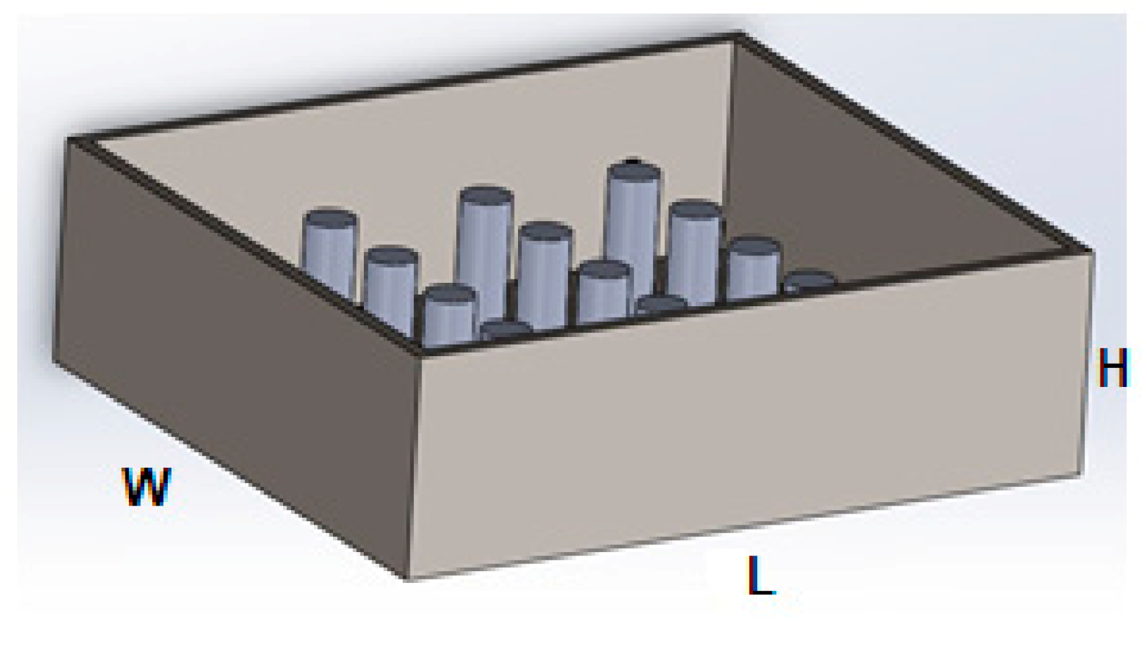
Figure 1. Conduction CAD Model.
Engproc 111 00006 g001
Figure 2. (a) Piping system; (b) Convection CAD model.
Engproc 111 00006 g002
Figure 3. Meshing of heat exchanger.
Engproc 111 00006 g003
Figure 4. Temperature contours: (a) Conduction; and (b) Convection.
Engproc 111 00006 g004
Figure 5. Average temperature distribution of both models.
Engproc 111 00006 g005
Figure 6. (a) Steel box with aluminum piping; and (b) Experimental setup.
Engproc 111 00006 g006
Figure 7. Sample compositions: (a) 100% silica sand; (b) 100% basalt rocks; (c) 30% silica sand and 70% basalt rocks; (d) 50% silica sand and 50% basalt rocks; (e) 65% silica sand and 35% basalt rocks; and (f) 70% silica sand and 30% basalt rocks.
Engproc 111 00006 g007
Figure 8. Temperature variation in samples.
Engproc 111 00006 g008
Figure 9. Heat storage of silica sand sample.
Engproc 111 00006 g009
Figure 10. Heat storage of basalt rocks sample.
Engproc 111 00006 g010
Figure 11. Heat storage of 30% silica sand and 70% basalt rocks sample.
Engproc 111 00006 g011
Figure 12. Heat storage of 50% silica sand and 50% basalt rocks sample.
Engproc 111 00006 g012
Figure 13. Heat storage of 65% silica sand and 35% basalt rocks sample.
Engproc 111 00006 g013
Figure 14. Heat storage of 70% silica sand and 30% basalt rocks sample.
Engproc 111 00006 g014
Figure 15. Heat storage of all six samples.
Engproc 111 00006 g015
Table 1. Features of the conduction model.
ParametersFeatures
Length of heat exchanger 45 cm
Width of heat exchanger 40 cm
Height of heat exchanger15 cm
Diameter of fin3 cm
Length of fin10 cm
Volume of heat exchanger27,000 cm3
Volume of fins85 cm3
Volume of mixture26,915 cm3
Table 2. Features of the convection model.
ParametersFeatures
Length of heat exchanger45 cm
Width of heat exchanger40 cm
Height of heat exchanger16.2 cm
Diameter of pipe3 cm
Length of pipe320 cm
Volume of heat exchanger29,160 cm3
Volume of pipe2197.78 cm3
Volume of mixture26,915 cm3
Table 3. Mesh independence study.
Number of Elements (103)Average Temperature (°C)
15.710
23.927
35.439
56.748
76.549
98.649
Table 4. Investigation parameters for simulations [8,12,21].
Material PropertiesValues
Sand Thermal Conductivity (W·m−1·k−1)2.56
Sand Heat Capacity (J·kg−1·k−1)703
Rocks Thermal Conductivity (W·m−1·k−1)2.08
Rocks Heat Capacity (J·kg−1·k−1)1028
Table 5. Testing samples and their proportions.
Proportion of Silica SandProportion of Basalt Rocks
85 kg (100%)0
065 kg (100%)
25.5 kg (30%)45.5 kg (70%)
42.5 kg (50%)32.5 kg (50%)
55.2 kg (65%)22.7 kg (35%)
59.5 kg (70%)19.5 kg (30%)
Disclaimer/Publisher’s Note: The statements, opinions and data contained in all publications are solely those of the individual author(s) and contributor(s) and not of MDPI and/or the editor(s). MDPI and/or the editor(s) disclaim responsibility for any injury to people or property resulting from any ideas, methods, instructions or products referred to in the content.