1. Introduction
Duplex stainless steels (DSSs) are emerging as strong substitutes to austenitic stainless steels due to their superior strength, which results in economic benefits and weight reduction. The term “duplex” refers to the dual-phase microstructure, characterized by an alternating banded pattern of austenite (the more abundant phase) and ferrite (the less abundant phase) [
1]. Super duplex stainless steel (SDSS), valued for its remarkable strength and resistance to corrosion, finds application in chemical reactors, marine desalination, power plant heat exchangers, coastal infrastructure, and oil and gas settings (pipelines, subsea systems). Machining is a critical manufacturing process that uses cutting tools to remove material and achieve a component’s final dimensions and geometry. Common operations include turning, milling, grinding, and drilling. Key parameters in turning operations are cutting speed, feed rate, depth of cut, tool selection, and workpiece material properties, all of which influence efficiency, tool life, and surface quality. Machining SDSS is challenging due to its high hardness, toughness, and low thermal conductivity, which accelerate tool wear and heat buildup [
2]. Rapid work hardening and adhesion cause built-up layers (BULs) on cutting tools, increasing forces and surface defects [
3]. Alloying elements such as Mo, Ni, and Cr increase the strength of SDSS but adversely affect its machinability. Lower speeds tend to promote built-up layer (BUL) formation, while higher speeds induce residual stresses and soft surface layers [
3]. Cutting fluids are commonly used in machining processes to provide cooling, lubrication, and effective chip removal; however, their use also introduces potential environmental and health hazards [
4]. In contrast, dry machining eliminates these risks but gives rise to challenges such as increased heat buildup, accelerated tool wear, and reduced surface quality due to friction and adhesion. These issues are further exacerbated in the machining of SDSSs due to their high work-hardening rate, low thermal conductivity, and pronounced adhesive tendencies, which together intensify heat generation and tool degradation. Additionally, the machined surface exhibits poor quality, including suboptimal dimensional accuracy and finish [
5]. An effective method to enhance the machinability of SDSS and prolong tool life is the application of a thin protective ceramic coating on the tool insert.
This can be achieved through techniques such as physical vapor deposition (PVD) or chemical vapor deposition (CVD). For instance, AlTiN coatings have been shown to extend tool lifespan by up to three times by reducing friction, improving chip evacuation, and lowering cutting forces [
5]. In dry machining, these coatings play a crucial role in preventing abrasion, thermal damage, and deformation of the tool. Additionally, they provide a synergistic balance between surface protection and core strength, enabling tools to endure extreme conditions. This not only enhances tool durability but also improves machining efficiency, resulting in superior workpiece quality with consistent precision. Parsi et al. [
6] investigated the machining performance of coated inserts during the turning of SDSSs. The results showed that PVD-coated AlTiN and AlCrN cutting inserts outperformed plain carbide inserts regarding tool wear, chip formation, and surface quality when turning SDSS-UNS32750. Sonawane and Sargade [
1] investigated the machining performance of AlTiCrN- and AlTiN-coated carbide tools during the dry turning of DSS 2205. The reported that the AlTiCrN and AlTiN coatings extended tool life by six and four times, respectively, compared to uncoated tools. Sonawane et al. [
7] characterized advanced PVD coatings and evaluated their machining performance during the dry turning of DSS2205 steel. The study correlated coating properties, including thickness, composition, layer sequencing, and deposition methods, with machining results. They reported that the AlTiCrN coatings placed using HiPIMS showed superior attributes and performance with 110 N adhesion strength, 0.19 µm surface roughness, and 124 min tool life, while AlTiN coating followed with 110 min of tool life. Yasar et al. [
8] compared CVD- and PVD-coated cutting tools in the dry turning of 17-4 PH stainless steel using Taguchi L16 design. Evaluating forces in cutting, surface quality, tool life, and chip formation, PVD coatings outperformed CVD, showing reduced forces, better surface finish, and longer tool life. ANOVA and regression analysis identified optimal parameters, concluding that PVD tools are a superior alternative for machining 17-4 PH stainless steel. Patil et al. [
9] evaluated PVD-coated tools (TiAlN, TiAlSiN) and uncoated WC-Co tools in dry orthogonal turning of duplex stainless steel. TiAlN-coated tools showed the best performance, while TiAlSiN’s effectiveness was reduced by oxygen traces. Surface roughness, cutting forces, and chip compression ratios were also evaluated. The study highlights TiAlN coatings as a superior choice for improving machining efficiency in dry-cutting SDSS operations.
This study investigates the dry turning of SDSS 2507 using coated inserts to evaluate tool wear. PVD coatings, such as AlTiN and AlCrN, are known for reducing friction, improving chip flow, and enhancing wear resistance during machining in duplex stainless steel machining. Previous studies show that PVD-coated tools outperform uncoated tools in reducing cutting forces, improving surface finish, and minimizing wear. Among coatings, TiAlN is one the coatings which demonstrates superior performance. These coatings offer better resistance to abrasion and deformation, resulting in good wear resistance in machining. While existing literature has primarily focused on the machining of stainless steel and SDSS 2205, very limited research has addressed SDSS 2507, particularly under dry machining conditions. SDSS 2507, a higher grade alloy with superior mechanical and corrosion-resistant properties, presents additional challenges that remain largely underexplored. This study investigates the dry machining of SDSS 2507 using PVD-coated inserts—an area with scarce prior research. The present work offers new insights that can support future developments in tool design and machining strategies. The experimental design of Taguchi was applied to perform experimentations, and their S/N ratios were used to examine the effect of the following key cutting parameters: cutting speed, feed rate, and depth of cut on tool wear. Additionally, the Taguchi analysis was used to suggest the optimal cutting parameter levels to minimize the flank wear. This study highlights the effectiveness of coated tools for the dry machining of SDSS 2507, offering a reliable solution for enhancing tool life and operational efficiency in industrial applications.
2. Materials and Methods
The experiments were conducted on SDSS grade 2507 using PVD-TiAlN-coated inserts of grade CNMG 120408 45 DP5010 on an Ace Micromatic Super Jobber 500 CNC machine tool. The tool holder of ISO grade MCLNL 2525 M12 was used to hold the cutting inserts. The critical machining factors, such as cutting speed (75–125 m/min), feed rate (0.04–0.18 mm/rev), and depth of cut (0.4–1.2 mm), were varied throughout the trials using the Taguchi L
9 array. The experimental design employed a Taguchi L
9 orthogonal array (3
3), which is a widely accepted and efficient approach within the Taguchi methodology for analyzing three parameters at three levels [
10,
11]. It enables optimal resource utilization while allowing for the effective evaluation of multiple factors and their influence on the response.
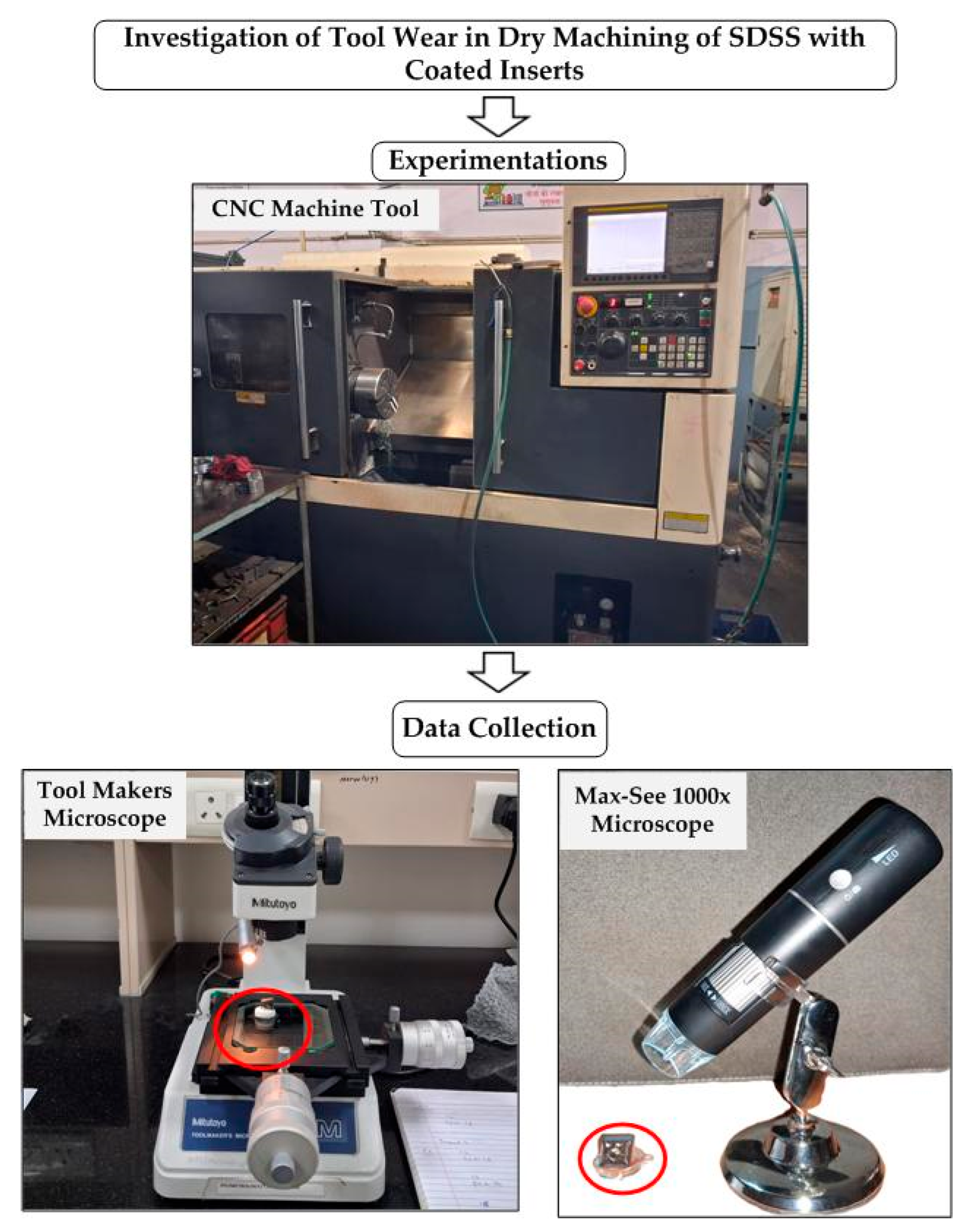
Figure 1 illustrates the framework of the proposed work. The experimental plan with combinations of cutting parameters is presented in
Table 1.
The cutting parameters for the turning experiments were selected based on available literature and recommendations from cutting insert suppliers. This investigation focuses on evaluating tool flank wear, as it is a critical factor in determining tool life. Fresh cutting inserts were used to perform each experiment, and the worn inserts were retained for further measurement of flank wear. Additionally, each turning cut was limited to 120 s. Flank wear was evaluated with the aid of a precision optical microscope, a Mitutoyo Tool Makers Microscope Model TM500 made in Japan, which has a least count of 0.005 mm and is presented in
Table 1. Further the key descriptive statistics of the measured flank wear, including mean, standard error, median, standard deviation, range, minimum, and maximum values, are summarized in
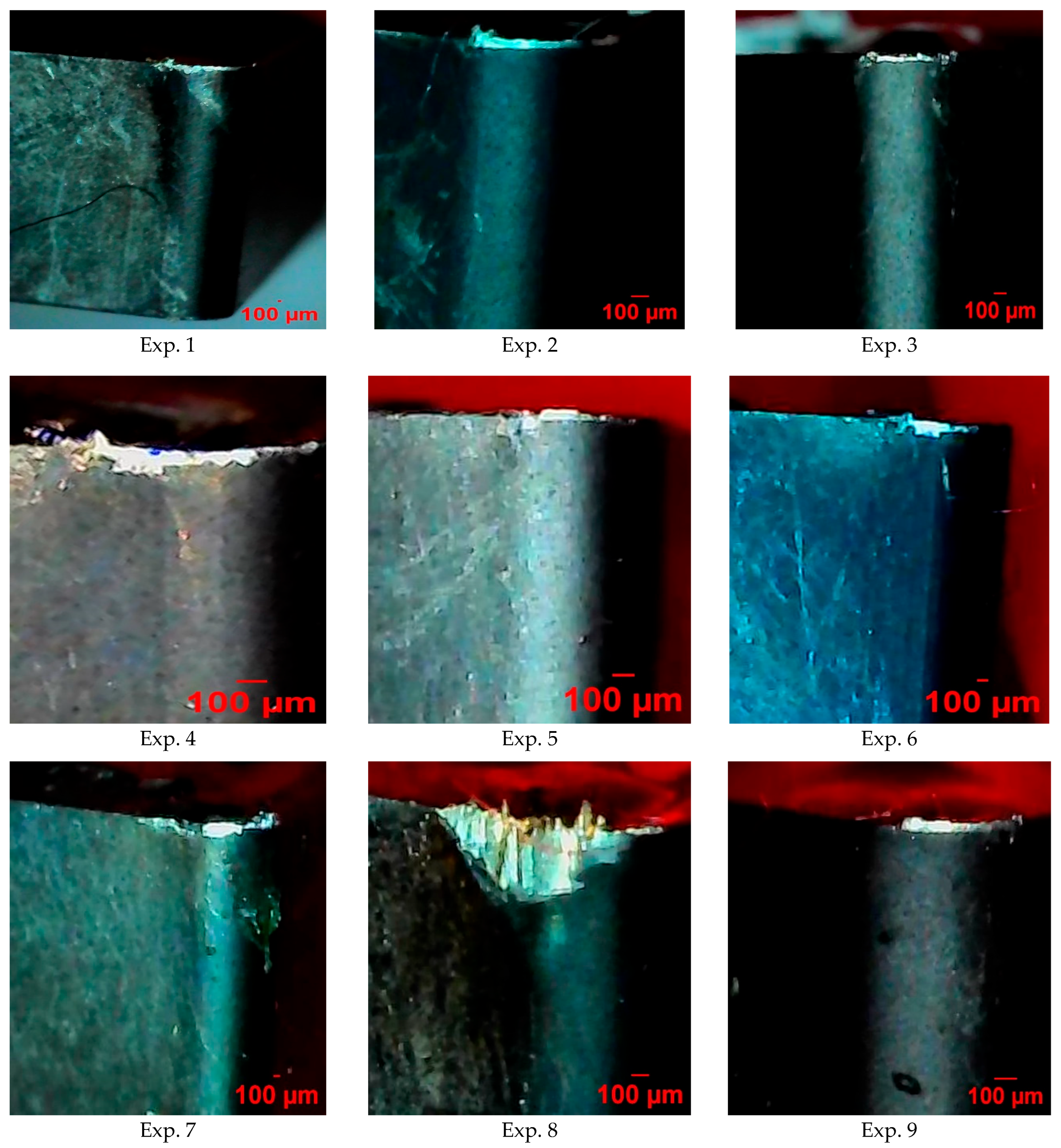
Table 2. Additionally, microscopic images of the worn cutting insert edges were captured using a MaxSee microscope made by Viboton, China, which has a magnification capacity of 1000×, and are presented corresponding to each experimental run in
Figure 2.
3. Results and Discussion
The present study investigates the dry machining of SDSS 2507 using PVD-TiAlN-coated inserts, with a focus on the critical performance parameter of cutting tool flank wear. Cutting tools are integral to machining processes including turning, and their performance significantly influences overall performance and output quality of the process. Tool failure, particularly due to wear, can have detrimental effects, including degraded surface finish, prolonged production times, and elevated machining costs [
12]. The tool flank wear is a critical factor that determines tool life. When the maximum flank wear reaches a predefined threshold value of 0.6 µm, the tool is considered worn out and requires replacement [
13]. The analyses of variance (ANOVA) for the linear and quadratic terms of flank wear are shown in
Table 3.
The ANOVA results shown in
Table 3 for the linear and quadratic terms of flank wear demonstrated a strong fit, explaining 96.51% of the total variability (
) with an adjusted
of 86.03%. The linear terms contributed 56.14%, while the quadratic terms accounted for 40.37%. However, the overall model was not statistically significant (
p = 0.101), likely due to the small sample size and limited error degrees of freedom (DF = 2), which reduced statistical power and increased uncertainty in
p-value estimation. Several model terms exhibited high F-values (>4), indicating strong contributions to variance, but their marginal or non-significant
p-values were attributed to the low error DF. Among the linear terms, feed rate (
) was the most influential, contributing 26.56% of the variability (F = 15.21,
p = 0.060). Depth of cut contributed 16.29% (F = 9.33,
p = 0.093), and cutting speed accounted for 13.30% (F = 7.62,
p = 0.110). Quadratic terms also showed notable effects, with
being particularly impactful, contributing 32.16% (F = 18.41,
p = 0.050). Conversely,
and
had weaker influences, contributing 3.54% (F = 2.03,
p = 0.291) and 4.67% (F = 2.68,
p = 0.244), respectively. Despite the model’s lack of overall significance, the high
and strong F-values suggest that feed rate, particularly its quadratic term, plays a dominant role in tool wear progression. Given the nature of the flank wear model developed and ANOVA results obtained, it is recommended to interpret the results with caution. Future studies with larger sample sizes are recommended to validate these findings.
Cutting parameters significantly influence the tool flank wear, necessitating an investigation of their effects. Among various analytical methods, Taguchi’s S/N ratio analysis is widely regarded as a proven technique for evaluating the impact of process parameters on responses. The S/N ratio measures the consistency of the response relative to the target value. Higher S/N ratios indicate settings that reduce variability and enhance performance. Depending on the nature of the response to be analyzed and aim of the experiment, different S/N ratio formulas are used, such as “larger is better,” “nominal is best,” or “smaller is better” [
12]. This method is employed in the present study to systematically analyze the cutting inserts flank wear. The Taguchi analysis is employed, with the results presented in
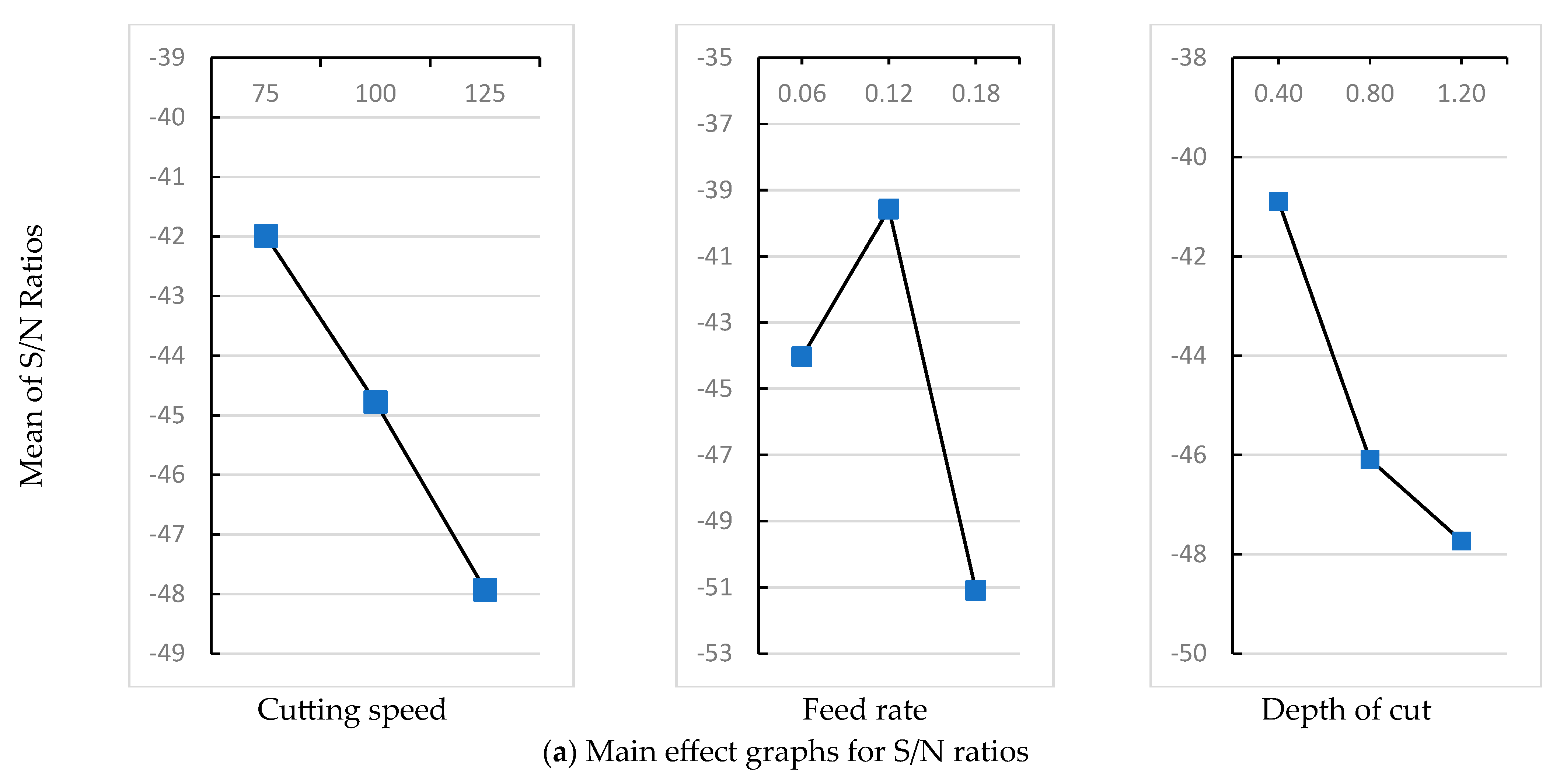
Table 4. Additionally, the main effect plots for the mean and S/N ratios of flank wear are illustrated in
Figure 3a,b, providing insights into the influence of each parameter on tool wear behavior and aiding in the identification of optimal machining conditions.
Table 1 highlights that the lowest flank wear of 70 µm was recorded at a
of 75 m/min, an
of 0.12 mm/rev, and a
of 0.8 mm. On the other hand, the highest flank wear of 515 µm was observed at a
of 125 m/min, an
of 0.18 mm/rev, and the same
.
Figure 3 illustrates how the machining parameters affect flank wear, providing a detailed analysis of both the mean values and signal-to-noise (S/N) ratios.
As illustrated in
Figure 3, a rise in cutting speed led to in a corresponding rise in flank wear. During the machining operation, it is strongly anticipated that the elevated cutting speed intensified the thermal and mechanical stresses acting on the cutting insert, resulting in greater heat generation and pressure at the tool–workpiece interface. This, in turn, resulted in increased wear on the insert and promoted the progression of wear mechanisms [
14]. As the depth of cut increases, a larger material volume is removed, resulting in greater heat generation and elevated stress levels. Deeper cuts typically lead to higher tool wear due to intensified contact and deformation in the primary shear zone, accelerating wear mechanisms. As
Figure 3 illustrates, increasing the depth of cut negatively affects the S/N ratios [
15]. Higher feed rates lead to a greater volume of material removal per unit time, resulting in elevated mechanical stresses and temperature on the cutting edge [
14]. This accelerates the wear of the tool. However, a slight improvement in the S/N ratio is observed with a rise in the feed rate from level 1 to level 2. The possible explanation is that at lower feed rates, the chances of built-up edge formation are higher due to prolonged tool–workpiece contact.
An increase in cutting parameter levels results in higher flank wear and a decline in the S/N ratios, consistent with anticipated trends. This behavior is attributed to the elevated mechanical and thermal stresses on the tool as cutting conditions become more intense, accelerating various wear mechanisms. All cutting parameters, including cutting speed, feed rate, and depth of cut, exhibit a consistent decline in the S/N ratios, indicating their negative impact on the tool–tip interface at higher levels. Higher S/N ratios indicate settings that minimize variability and enhance performance. Accordingly, as shown in
Figure 3, the optimal machining conditions for minimizing flank wear were determined to be a
of 75 m/min, an
of 0.12 mm/rev, and a
of 0.4 mm. Further, as shown in
Table 4, the Taguchi analysis revealed that feed rate was the primary factor influencing tool wear, with depth of cut and cutting speed following in significance. These results are further supported by the ANOVA analysis presented in
Table 3, which also identifies feed rate as the most significant contributing factor, followed by depth of cut and cutting velocity. The findings align with existing literature, as Zafar et al. [
16] reported that feed rate is the primary influential factor for flank wear in machining mild steel.
The wear of cutting tools is primarily due to abrasion, adhesion, and diffusion. As shown in
Figure 2, abrasive marks on the flank face are relatively uniform; however, the coating serves as a protective barrier, minimizing direct contact and mitigating these wear mechanisms, thereby enhancing wear resistance. Consequently, lower flank wear is observed under the given machining conditions. The work-hardening tendency of DSS materials further amplifies flank wear, increasing stress on the tool. Notably, the image corresponding to experiment number 8 in
Figure 2 clearly shows a notching effect, suggesting that higher cutting speeds combined with a fast tool feed (high feed rate) exacerbate this tendency, posing significant challenges and accelerating tool wear.


