Abstract
Small-scale wind turbines are becoming increasingly important in renewable energy systems due to their ability to operate in low-wind-speed environments and adapt to various installation locations, especially in areas with energy shortages. This paper presents the design, analysis and development of a Helical Vertical Axis type Wind Turbine (H-VAWT) using uPVC pipe as the blade material, offering a lightweight, low-cost, and corrosion resistant solution. The blade structure is optimized for use in residential and off-grid areas with unstable wind conditions. Structural analysis is conducted in ANSYS, including static load analysis (deformation, equivalent stress, shear stress, maximum stress), torsional and bending stress, and modal analysis to assess mechanical performance and vibrational stability. Three blade designs are initially considered, and the helical model (0–45° twist) is selected based on simulation results. The prototype is successfully fabricated and tested under different wind speeds, showing effective power generation, with favorable results in power output, power coefficient, tip-speed ratio (TSR), and relative velocity.
1. Introduction
Wind energy is a rapidly growing sector within the global renewable energy landscape due to its environmental benefits, scalability, and the increasing urgency to transition away from fossil fuel-based power generation. It represents an inexhaustible, clean source of energy that contributes significantly to the reduction in greenhouse gas emissions and supports sustainable development goals. According to Archer and Jacobson [1], the kinetic energy available in atmospheric wind currents has the potential to generate more than forty times the current global electricity demand. Despite this vast potential, wind power accounted for approximately 7.8% of global electricity generation by the end of 2023, with total installed wind capacity surpassing 1020 GW [2], highlighting the need for broader and more diversified implementation of wind energy technologies.
In recent decades, the Global Wind Energy Council reported a record addition of 116 GW in 2023, indicating growing global investment in wind infrastructure [3]. Projections by the International Renewable Energy Agency suggest that global wind capacity could exceed 2000 GW by 2030, aligning with current climate targets [4]. Additionally, the levelized cost of electricity (LCOE) for onshore wind has decreased by nearly 70% between 2010 and 2023, while offshore wind declined by about 60%, making wind energy economically competitive with conventional energy sources [5].
Technological advancements have contributed to this growth, particularly in turbine design and materials. Horizontal Axis Wind Turbines (HAWTs) have historically dominated the industry due to their high efficiency and aerodynamic refinement [6]. However, HAWTs require complex yaw mechanisms to align with the wind direction, making them less effective in urban or low-wind environments. In contrast, Vertical Axis Wind Turbines (VAWTs) can capture wind from all directions and have a simpler design, making them suitable for decentralized and rooftop applications [6,7]. Among VAWT configurations, the helical blade design has attracted attention due to its smoother torque output, reduced vibration, and enhanced aerodynamic efficiency under turbulent flow conditions [8,9].
Recent research has explored various aspects of VAWT performance. Rezaeiha et al. [7] showed that optimized helical VAWT blade profiles improved performance in urban environments through CFD analysis [8] analyzed the 3D aerodynamic flow in helical turbines and concluded that such designs produce more stable and continuous torque. Mohamed [9] reported increased efficiency by using new airfoil shapes in H-rotor turbines, and Islam et al. [10] evaluated aerodynamic models for Darrieus turbines and highlighted the limitations of straight-bladed designs in low-wind areas. Akwa et al. [10] reviewed the Savonius turbine’s mechanical output and confirmed its simplicity but lower efficiency, while Dai and Lam [11] used FEM to analyze stress in Darrieus blades and identified structural vulnerabilities under dynamic loading. Bharti et al. [12] experimentally verified the suitability of PVC blades for low-speed wind applications, showing acceptable performance and affordability. Similarly, Ullah et al. [13] demonstrated through simulation that polymer-based materials could endure structural loads while maintaining low fabrication costs.
Despite these advancements, a clear research gap remains in combining lightweight, corrosion resistance materials like uPVC with helical blade geometries and validating them through both structural analysis and physical testing. Most prior works focus either on composite materials or on simulations without real-world validation, limiting their practical applicability in cost-sensitive settings. This work presents the design, finite-element analysis, and prototype testing of a small-scale Helical Vertical Axis Wind Turbine (H-VAWT) fabricated from uPVC pipe blades. In ANSYS 2020, we perform static, torsional and modal simulations to evaluate stress distribution, deformation, torque output and vibration response. A physical model is tested under varying wind speeds to verify real-world performance. By leveraging locally available materials and simple fabrication techniques, our goal is to deliver a mechanically reliable turbine that is suitable for low-wind, decentralized or residential applications.
2. Methodology
This section describes the complete workflow of the turbine blades. It begins with the choice of suitable blade representations, followed by static structural justification and an in-depth investigation of a helical blade. Finally, it explains the applied steps taken to fabricate the VAWT blades using uPVC pipe.
2.1. Parameters for Turbine Blade
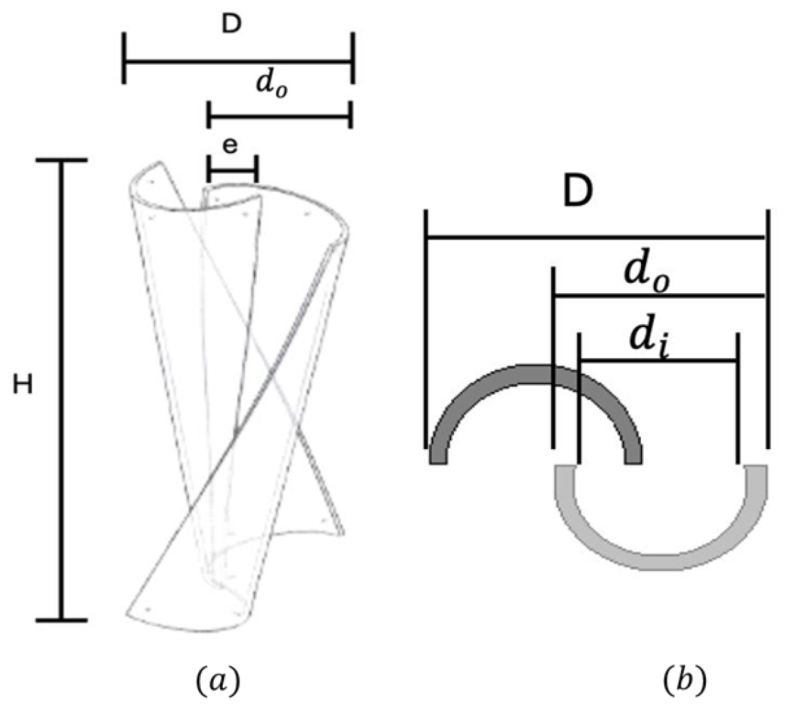
This work presents the structural design and the output evaluation of the turbine which is aimed at off-grid and urban power production in little wind speed environments. The turbine features two spiral blades fabricated from ASTM D1785-94 compliant pipe of uPVC, chosen because of its affordability, wide availability, corrosion resistance, and lightweight characteristics, the qualities that make it well-suited for roof and regionalized areas. The turbine’s structure follows established design procedures for optimum vertical-axis performance, with an aspect ratio (AR)—defined as the ratio of blade height (H) to rotor diameter (D)—maintained between 1.5 and 2 to ensure an equilibrium between aerodynamic efficiency and structural stability [14]. Figure 1 explains a graphic illustration of the turbine and significant geometric parameters, where H is the tallness (or span) of the blades, D is the Diameter of the rotor, is the overlap distance, is the outer diameter of the blade, and is the inner diameter of the blade.
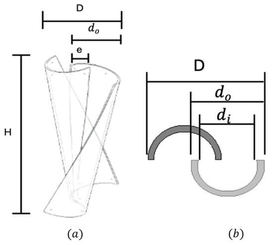
Figure 1.
The figure provides a schematic representation of the turbine along with its main geometric parameters. (a) Isometric view of H-VAWT (b) Top view of the turbine blades.
For this design the aspect ratio is:
where inch.
By referring to ASTM D1785-94 uPVC pipe, we take the diameter of the blades as follows.
Therefore, the thickness of the blade is 0.365 in and the number of blades of the turbine are 2.
The maximum power coefficient is achieved at an optimum overlap ratio of 0.2 [13].
So, the diameter takes as.
the appropriate overlap ratio is 20% to 30% [13]
The energy-capturing capability of a helical axis rotor largely depends on its swept area .
This area defines the interface region amongst the incoming airflow and rotor. The Tip Speed Ratio (TSR) serves as a key performance parameter that characterizes the turbine’s efficiency and dynamic behavior.
where λ is dimensionless and shows Tip Speed Ratio, and ω is representing the angular velocity given in rad/s and R = Radius given in meters.
V is in m/s and represents the Flow velocity.
Therefore,
This TSR value is suitable for small-scale helical VAWTs, which generally perform well at lower λ values due to smoother torque characteristics and better performance in turbulent flow conditions.
The material selection of uPVC pipe is justified by its accessibility, low machining requirements, and satisfactory mechanical strength for small wind systems. Unlike composites or aluminum alloys, uPVC allows for simplified manufacturing without the need for specialized fabrication equipment, thus aligning with the project’s goal of creating a low-cost, easily deployable wind energy solution.
2.2. Design Selection and Analysis of Turbine Blade
The design selection and analysis of the turbine blade involved three different blade models, each created using distinct cutting methods. In our design, the blades were formed by making precise diagonal cuts on a cylindrical PVC pipe based on angular markings. For the small-scale VAWT design, three blade geometries were developed from PVC pipe. Model 1 (Straight Blade, 0° cut) was created by splitting the pipe into two symmetrical halves. Model 2 (Helical Blade, 45° twist) was produced by diagonal cuts that introduced a sharper helical profile. Model 3 (Helical Blade, 90° twist) followed a similar approach but with a gentler 90° twist. All three models were designed in SolidWorks 2024 and analyzed in ANSYS 2020 Workbench for static structural performance under identical wind loading conditions. The aim was to identify the most structurally stable and manufacturable design using uPVC as the blade material among the three models. Fixed supports were applied at the blade mounting edge to simulate hub attachment, with uniform wind pressure and gravity included to reflect realistic operating conditions.
2.3. Numerical Modeling and Simulation Setup
A structural simulation was conducted using ANSYS 2020 Workbench to assess the mechanical behavior of the helical VAWT under real-world operating conditions. The study included static structural analysis, torsional loading, and modal vibration evaluation. The blade geometry was discretized using a 3D unstructured tetrahedral mesh. A mesh sensitivity analysis was performed by varying the element size from 0.01 m to 0.001 m. Results showed convergence at an element size of 4.429 × 10⁻³ m, which was adopted for the final model. The blades were modeled using uPVC material due to its cost-effectiveness, availability, and mechanical reliability and its properties are given in Table 1.

Table 1.
Yield strength of used material [15,16].
Boundary conditions included fixed support at the base of the shaft, applied rotational torque, and a small lateral aerodynamic load to replicate wind-induced forces. Simulations were performed using an iterative Newton–Raphson solver with a convergence criterion of 1 × 10⁻⁴. The analysis showed that the 0–45° helical blade exhibited the least deformation (~3.54 × 10⁻⁷ m), a moderate equivalent stress (~4587 Pa), and manageable shear stress (~269.77 Pa), outperforming both the straight and 90° helical models in structural stability and practicality. Mesh refinement was applied near stress-concentration zones, and a mesh independence study confirmed that a 70 mm element size provided accurate results with low computational cost. The Von Mises criterion was used for failure analysis due to PVC’s ductile nature, ensuring the design remained within the elastic region under applied loads.
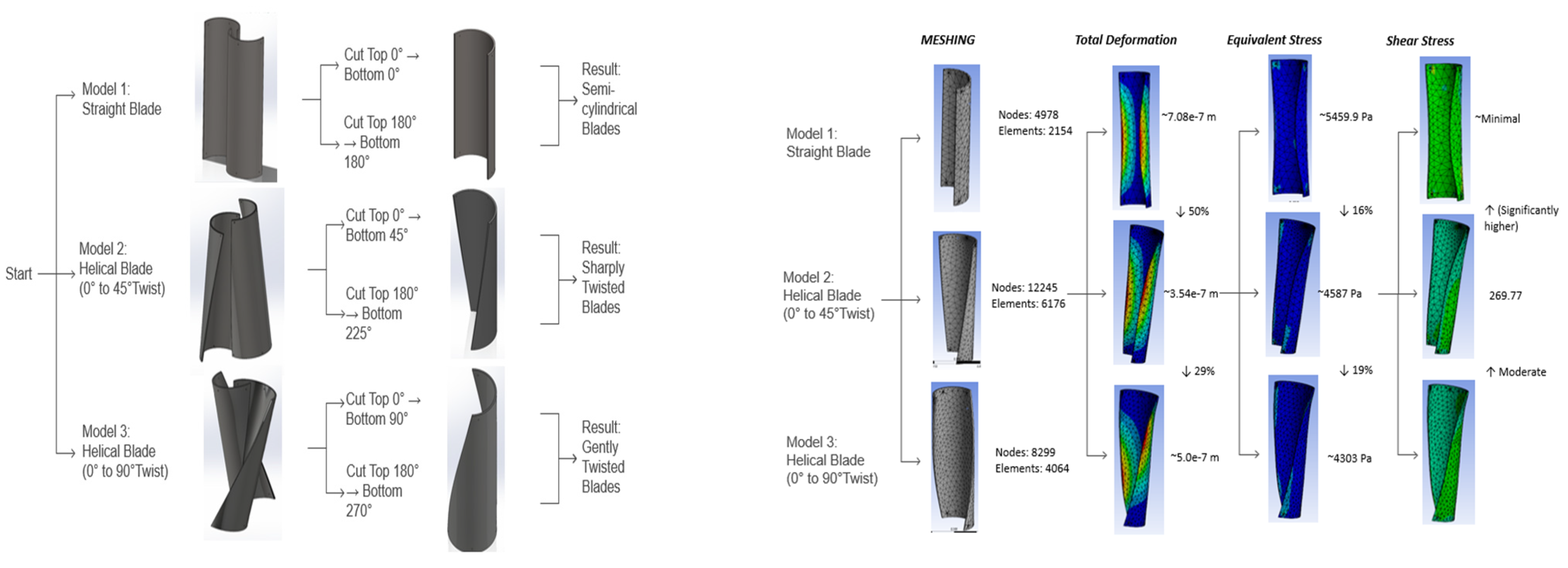
In Figure 2, three blade models were designed using PVC pipe to evaluate the mechanical behavior of different blade profiles for the proposed vertical axis wind turbine (VAWT). Model 1 (Straight Blade) was developed by making two vertical cuts at 0° and 180°, producing symmetrical semi-cylindrical sections. Model 2 (Helical Blade 0–45°) introduces a diagonal twist by cutting from the top at 0° to the bottom at 45°, and similarly from 180° to 225°, resulting in a moderate helical shape. Model 3 (Helical Blade 0–90°) incorporates a smoother and more gradual twist with cuts from 0° to 90°, and 180° to 270°. All three designs were created in SolidWorks 2024 and analyzed using ANSYS 2020 Workbench under identical loading conditions (wind and gravity). The analysis focused on total deformation, equivalent (von Mises) stress, and shear stress. Among the three, the 0–45° helical blade (Model 2) showed the most favorable performance, offering low deformation while maintaining structural integrity and ease of manufacturing.
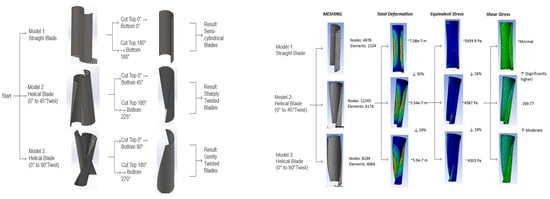
Figure 2.
The figure illustrates the Blade models of the proposed vertical axis wind turbine staring from Straight Blade (0°) to Helical Blade (0–45°), and Helical Blade (0–90°).
Manufacturing feasibility was also a key factor in which the 45° twist could be safely achieved by heating and twisting PVC without risk of cracks or warping, unlike the more extreme 90° twist. Based on deformation, stress performance, and ease of fabrication, the 0–45° helical blade was determined to be the optimal choice for reliable, efficient, and scalable wind turbine application. The evaluation details are given in Figure 3.

Figure 3.
Evaluation of PVC blade twist angles. A 45° twist was found optimal, balancing aerodynamic performance with ease of fabrication and structural integrity, unlike the less feasible 90° twist.
2.4. Grid Independence and Validation Study
To ensure accuracy and consistency in the simulation results, a grid independence analysis was carried out for the three proposed blade models: Straight Blade (Model 1), Helical Blade 0–45° (Model 2), and Helical Blade 0–90° (Model 3). Mesh quality was improved using body sizing and face sizing features in ANSYS 2020 Workbench, with the default element size of 4.429 × 10⁻³ m maintained for all models. Due to the varying geometric complexity, each model required a different number of nodes and elements to achieve convergence. The complete details for different blade models are given in Table 2.

Table 2.
Mesh and Result Comparison for Blade Models.
As given in the results in Table 2, deformation and stress values decrease with improved blade geometry, and results stabilize with mesh refinement. The 0–45° helical model showed the best structural performance, combining low deformation with acceptable stress levels. This convergence confirms that the applied mesh settings are reliable, and further refinement would not significantly affect accuracy as shown in Figure 2. To validate the accuracy of the numerical model, a prototype of the selected 0–45° helical blade model was fabricated using uPVC pipe and tested under static loading. The deformation at the blade tip was measured using a dial indicator. The experimental result showed a tip displacement of approximately 5.38 × 10⁻⁷ m, compared to the simulated value of 5.16 × 10⁻⁷ m. The difference of less than 5% confirms good agreement between the simulation and physical testing, validating the fidelity of the finite element model used in this study.
3. Results
3.1. Analysis Results for Helical Blades (0° to 45°)
Static Load Analysis:
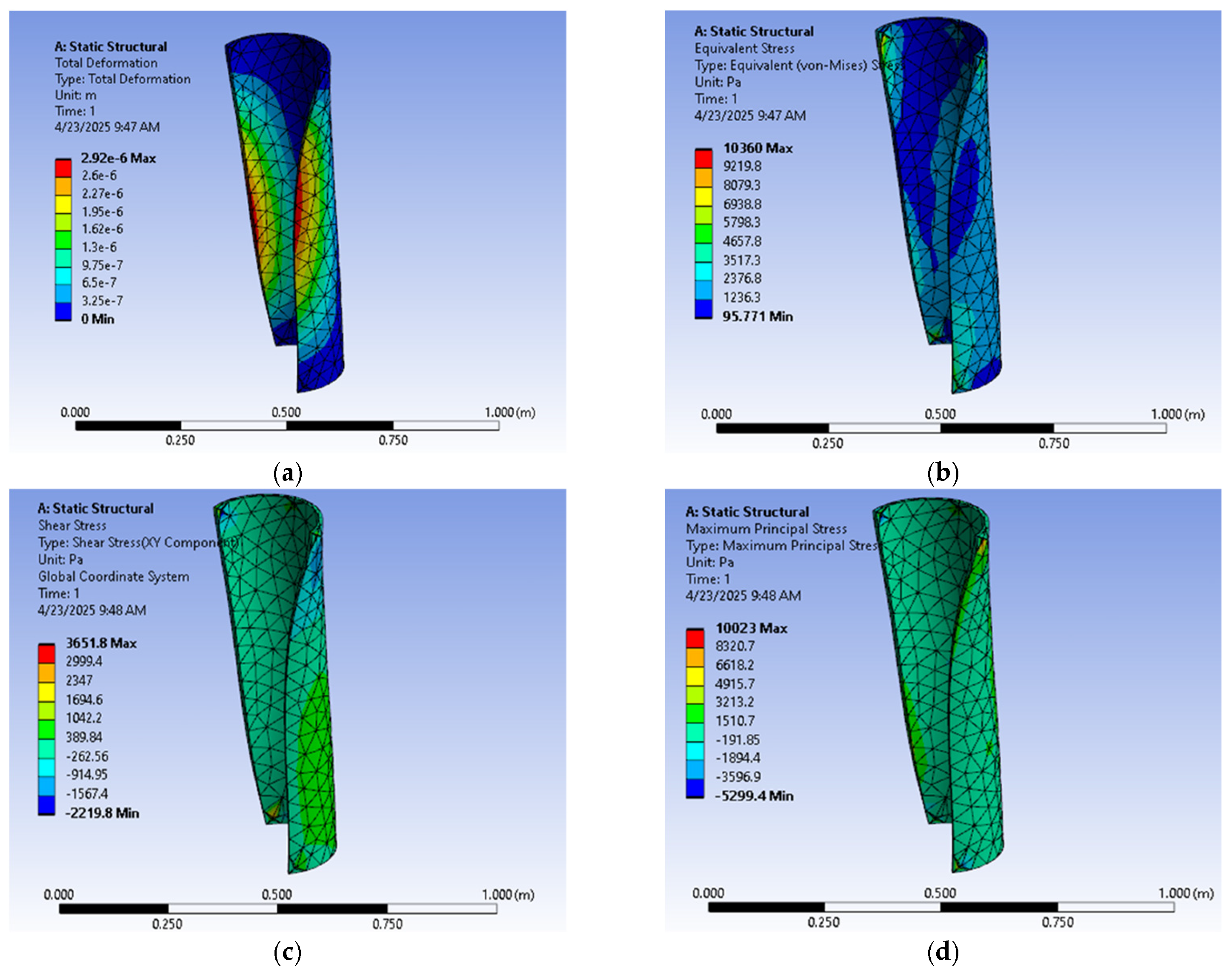
Static load analysis in ANSYS 2020 Workbench showed minimal deformation (5.16 × 10⁻⁷ m), confirming the blade assembly’s high stiffness as shown in Figure 4. The von Mises stress (1781.9 Pa), shear stress (103.65 Pa), and principal stress (737.32 Pa) were all far below the yield strength of mild steel, ensuring structural safety under static loading.
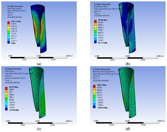
Figure 4.
Static load analysis of the turbine blade assembly: (a) Total deformation (max 5.16 × 10⁻⁷ m) indicating high stiffness, (b) von Mises stress (max 1781.9 Pa) within safe limits, (c) shear stress distribution (max 103.65 Pa), and (d) principal stress (max 737.32 Pa) confirming structural integrity.
Torsional & Bending Stress:
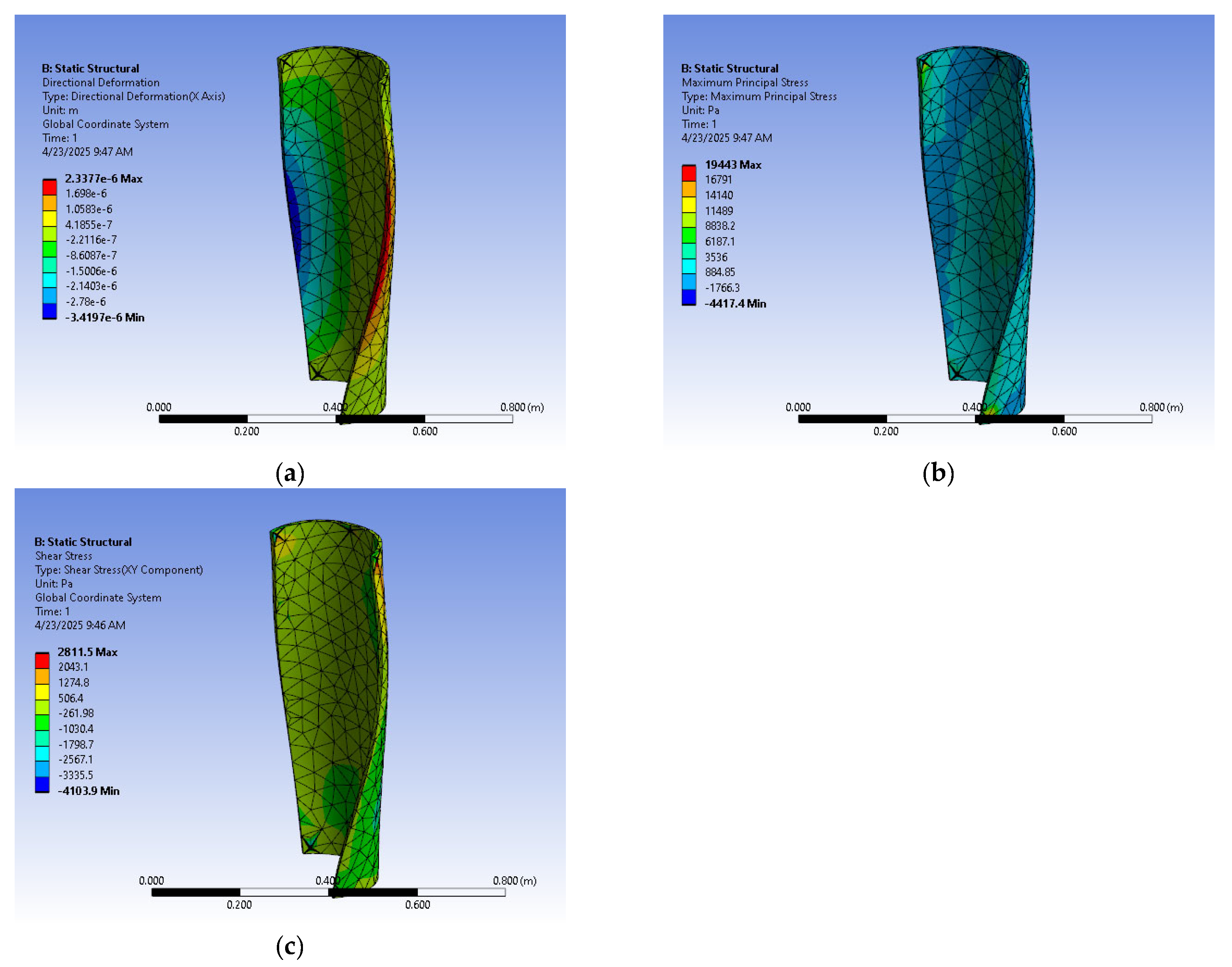
The directional deformation plot shows a maximum displacement of about 2.34 × 10⁻⁶ m along the X-axis, mainly at the blade’s trailing edge where bending and twisting forces are highest. These micro-level deformations confirm the uPVC blade’s structural stability and reliability under expected loads (Figure 5).
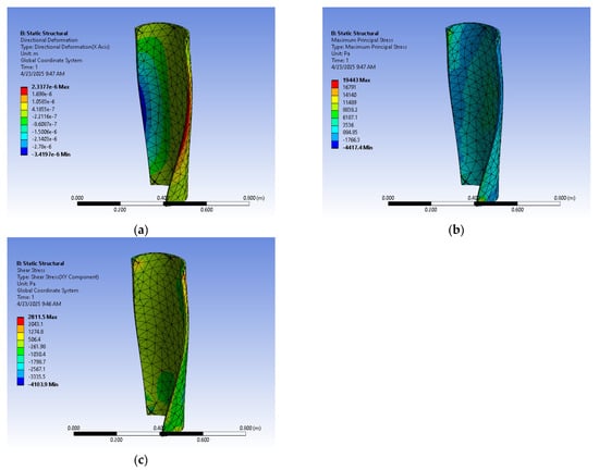
Figure 5.
(a) The maximum deformation observed is approximately 2.34 × 10⁻⁶ m along the X-axis, with prominent displacement near the trailing edge due to the interaction of bending and twisting forces (b) the maximum princpal stress is 19,443 Pacal confirming the structure’s integrity. (c) Shear stress distribution across the turbine blade assembly under static loading, with a peak value of 2811.5 Pa.
The results of modal analysis for the proposed design are given in Table 3.

Table 3.
Modal Analysis of the proposed design.
The range of the turbine operation is:
- i.
- ~67 RPM
- ii.
- ~134 RPM
- iii.
- ~198 RPM
The turbine’s operating speed is far below its first natural frequency (~6190 RPM), keeping it well clear of resonance risks. Given its low-speed operation and smooth torque from helical blades, dynamic effects are minimal. Thus, static, torsional, bending, and modal analyses were sufficient to confirm structural safety. A detailed dynamic analysis may be explored in future work but is not critical for this design.
3.2. Motor with Base Frame and Blades Mountiting
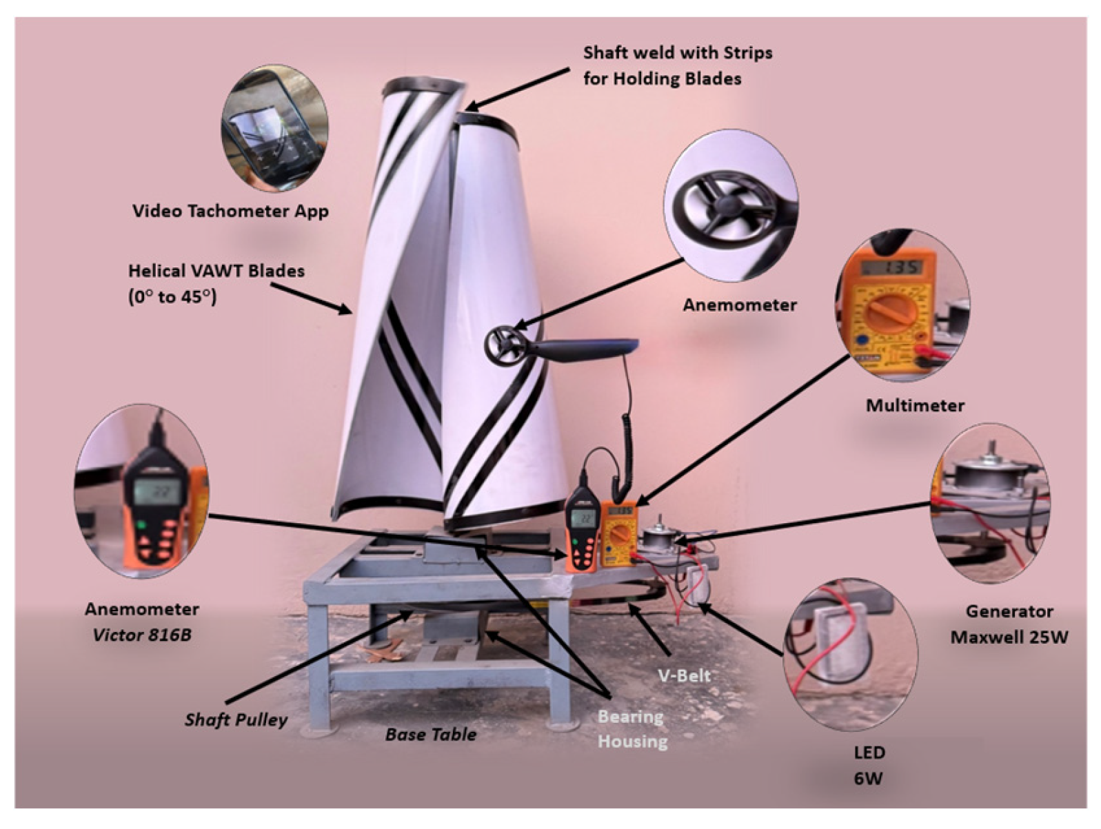
The pipes made up of uPVC Class D were chosen for the blades because of their light weight and easiness of shaping. Each pipe was cut, twisted into a 0–45° helical profile, and finished for balance and smooth rotation. The blades were mounted using MS support strips, bolts, and mild steel bushes for added rigidity. The rotor prototype was then assembled and coupled to a motor mounted on a base frame with a pulley system for power transfer. The setup was equipped with multimeter, tachometer app and anemometer to record speed of the wind, voltage, current, and RPM, while LEDs provided a simple visual indication of power generation. The complete experimental arrangement is shown in Figure 6.
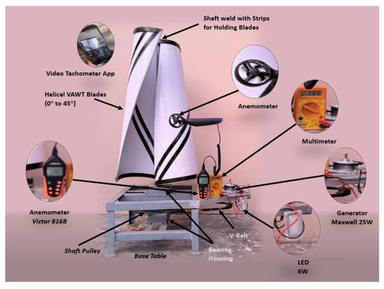
Figure 6.
Schematic diagram for experimental evaluation of Helical Axis Wind Turbine (0° to 45°).
In the practical evaluation using a 12 V, 25 W Maxwell DC motor, tests were conducted to assess the electrical and mechanical output of a VAWT with 0–45° helical blades. At 2.8 m/s wind speed, the turbine produced 3.12 W (1.96 V, 1.59 A) at 60 RPM, while at 8.5 m/s it reached 300 RPM and 14.28 W output, showing a near-proportional performance increase with wind speed. Mechanical power rose from 2.49 W to 11.42 W, and torque remained stable between 0.30 and 0.40 Nm, indicating good structural integrity. Tip Speed Ratio peaked at 1.36, consistent with low-to-medium wind speed operation. The overall experimental results of the proposed design are given in Table 4.

Table 4.
Experimental results of the proposed design.
Table 4 shows the performance of the fabricated helical VAWT across wind speeds from 2.8 to 8.5 m/s. With increasing wind speed, RPM, voltage, current, and power output all rose consistently, confirming effective response to varying conditions. The turbine began generating power at just 2.8 m/s (3.12 W), highlighting its low cut-in speed and appropriateness for urban, low-wind sites. At 8.5 m/s, it reached 300 RPM and 14.28 W output. Torque remained stable (0.32–0.40 Nm), while wind power and tip speed increased to 237 W and 11.57 m/s, accordingly. These results demonstrate the turbine’s structural reliability and potential for small-scale renewable generation.
Structural analysis showed well-distributed support forces (0.49–2.17 N) and safe stress values under a 5 N edge load and 0.76 Nm moment, with max principal stress at 1442.5 Pa, shear stress at −95.65 Pa, and minimal deformation (–1.11 × 10⁻⁷ m). The helical blade shape proved effective in load distribution, reducing stress concentration and torque pulsation, leading to stable performance without excessive vibration, validating its suitability for small-scale wind energy applications. In this work, the focus was on the structural performance and manufacturability of the helical blade design using low-cost materials. Since the primary goal was to evaluate structural reliability under expected loads, we prioritized mechanical simulation (static, torsional, and modal analysis). Additionally, performing accurate CFD for helical VAWTs requires complex transient simulation and significant computational resources, which were beyond the current study’s scope.
4. Conclusions
This paper successfully covered the complete design, analysis, and fabrication of a vertical axis wind turbine (VAWT) featuring a 0–45° helical blade configuration. Multiple initial design models including straight 0–0°, semi-helical 0–45°, and full-helical blades 0–90° were developed and compared using CAD modeling and simulation. The CAD modeling and analysis identified the 0–45° helical design as optimal, offering better load distribution and minimal deformation. The blades were fabricated from uPVC and mounted on a base frame with angle bars, bearings, shafts, and pulleys. A 12 V DC motor was used for testing, with voltage, current, RPM, and wind speed measured through standard instruments. The turbine generated power even at low wind speeds, confirming its practical viability. Structural tests confirmed that stress and reaction forces remained within safe limits, and the assembly process covering blade shaping, frame construction, and motor integration demonstrated solid mechanical reliability. Overall, the 0–45° helical blade VAWT design showed strong potential for efficient and stable small-scale wind energy generation.
Author Contributions
Conceptualization, methodology, investigation, data curation, H.B.R. and H.S.Z.; writing—original draft preparation, H.B.R. and H.S.Z.; editing, M.S.M. and M.A.; review, S.K.H. and M.I. All authors have read and agreed to the published version of the manuscript.
Funding
This research received no external funding.
Institutional Review Board Statement
Not applicable.
Informed Consent Statement
Not applicable.
Data Availability Statement
No new data were created or analyzed in this study. Data sharing is not applicable to this article.
Conflicts of Interest
The authors declare that the research was conducted in the absence of any commercial or financial relationships that could be construed as a potential conflict of interest.
References
- Archer, C.L.; Jacobson, M.Z. Evaluation of global wind power. J. Geophys. Res. Atmos. 2005, 110, D12110. [Google Scholar] [CrossRef]
- Growth in Global Energy Demand Surged in 2024 to Almost Twice its Recent Average, 2025. Available online: https://www.iea.org/news/growth-in-global-energy-demand-surged-in-2024-to-almost-twice-its-recent-average (accessed on 11 May 2025).
- Global Wind Workforce. Available online: https://www.globalwindsafety.org/statistics/global-wind-workforce-outlook-2024---2028 (accessed on 20 May 2025).
- Renewable Energy Statistics 2025, in International Renewable Energy Agency, 2025. Available online: https://www.irena.org/Publications/2025/Jul/Renewable-energy-statistics-2025 (accessed on 3 August 2025).
- 2023 Year in Review: Climate-Driven Global Renewable Energy Potential, Resources and Energy Demand, in World Meteorological Organization, 2025. Available online: https://wmo.int/publication-series/2023-year-review-climate-driven-global-renewable-energy-potential-resources-and-energy-demand (accessed on 22 April 2025).
- Manwell, J.F.; McGowan, J.G.; Rogers, A.L. Wind Energy Explained: Theory, Design and Application, 2nd ed.; John Wiley & Sons: Hoboken, NJ, USA, 2010. [Google Scholar]
- Rezaeiha, A.; Montazeri, H.; Blocken, B. Towards optimal aerodynamic design of vertical axis wind turbines: Impact of solidity and number of blades. Energy 2018, 165, 1129–1148. [Google Scholar] [CrossRef]
- Ferreira, C.S. The Near Wake of the VAWT-2D and 3D Views of the VAWT Aerodynamics. Ph.D. Thesis, Delft University of Technology, Delft, The Netherland, 2009. [Google Scholar]
- Mohamed, M. Performance investigation of H-rotor Darrieus turbine with new airfoil shapes. Energy 2012, 47, 522–530. [Google Scholar] [CrossRef]
- Islam, M.; Ting, D.S.-K.; Fartaj, A. Aerodynamic models for Darrieus-type straight-bladed vertical axis wind turbines. Renew. Sustain. Energy Rev. 2008, 12, 1087–1109. [Google Scholar] [CrossRef]
- Dai, Y.M.; Lam, W. Numerical study of straight-bladed Darrieus-type tidal turbine. Proc. Inst. Civ. Eng.-Energy 2009, 162, 67–76. [Google Scholar] [CrossRef]
- Patil, H. Experimental work on horizontal axis PVC turbine blade of power wind mill. Int. J. Mech. Eng. 2012, 2, 75–85. [Google Scholar]
- Thiyagaraj, J.; Rahamathullah, I.; Anbuchezhiyan, G.; Barathiraja, R.; Ponshanmugakumar, A. Influence of blade numbers, overlap ratio and modified blades on performance characteristics of the Savonius hydro-kinetic turbine. Mater. Today Proc. 2021, 46, 4047–4053. [Google Scholar] [CrossRef]
- Meirovitch, L. Fundamentals of Vibrations; McGraw-Hil: New York, NY, USA, 2001. [Google Scholar]
- Callister, W. Materials Science and Engineering: An Introduction, 10th ed.; Wiley: Hoboken, NJ, USA, 2018. [Google Scholar]
- Oberg, E.; Jones, F.; Horton, H.; Ryffel, H. Machinery’s Handbook, 29th ed.; Mccauley, C.J., Ed.; Industrial Press Inc: New York, NY, USA, 2012. [Google Scholar]
Disclaimer/Publisher’s Note: The statements, opinions and data contained in all publications are solely those of the individual author(s) and contributor(s) and not of MDPI and/or the editor(s). MDPI and/or the editor(s) disclaim responsibility for any injury to people or property resulting from any ideas, methods, instructions or products referred to in the content. |
© 2025 by the authors. Licensee MDPI, Basel, Switzerland. This article is an open access article distributed under the terms and conditions of the Creative Commons Attribution (CC BY) license (https://creativecommons.org/licenses/by/4.0/).

