Abstract
Sol-gel coatings provide environmentally friendly surface protection for metals and can replace toxic pre-treatments such as those based on hexavalent chromium on metal alloys. This project ultimately aims to develop silica-based organic–inorganic sol-gel derived thin film coatings possessing anti-corrosion and anti-fouling properties on aluminium alloy substrates. As with any coating, sample preparation plays a significant role in the performance of a sol-gel coating. Therefore, it was necessary to define a preparation method that combines the removal of contaminants and surface roughening to improve adhesion and reproducibility. Four techniques were investigated: fine abrasive sandpaper cleaning, acetone degreasing only and cleaning with an industrial-available alkaline cleaner for 5 min and 30 min.
1. Introduction
Aluminium alloys are still considered one of the primary light, high-strength alloys that can be used in aerospace and marine structures with a moderate economic cost. However, depending on the type and grade, aluminium alloys are vulnerable to aggressive environments [1,2]. Surface pollutants, such as organic dirt, grease and lubricants, must be removed to promote ionic or mechanical bonding between coatings and the substrates. Some of the practising procedures focus on degreasing more than removing oxides or cladding film, as it still reduces the corrosion propagation in the surface [3]. The standard aluminium alloys surface preparation in marine application can be achieved using a high alkaline solvent jet to remove the organic and greasing residual from 5 to 30 min, then it could be followed or mixed with sandblasting to remove the oxide film [4].
Hybrid silica-based sol-gel coatings have already been recognised as a potential corrosion mitigation solution for aerospace and marine use as an eco-friendly method [5,6], offering many routes, including using single-or multi-layer coating systems with anti-corrosion and anti-fouling systems. [5,7,8,9] Additionally, sol-gel coatings can present other desirable properties, such as preventing ice accumulation, oxidation resistance and abrasion resistance [10,11,12]. However, in sol-gel, the adhesion mechanism with aluminium alloys’ surface is different from the other coating types; it is based on (M-O-Si) strong ionic bonding. Therefore, This paper will study the optimisation of sample preparations techniques of the aluminium alloy 2024-t3 for the sol-gel coating used in the previous project [1]. This investigation analyses four types of surface preparation that suit the sol-gel coating technology to provide proper bonding for protection against corrosion.
2. Experimental Work
The testing and characterisation of the techniques will be conducted in two main steps. The first one will examine the treated substrates without the presence of any sol-gel coating by investigating the morphology, appearance, phase construction and XRD analysing techniques. The second step will occur after applying the sol-gel coating on four different treated samples and applying an electrochemical impedance spectroscopy preliminary test to evaluate the corrosion mechanism protection within 6 days in a 3.5% NaCl solution to simulate the aggressive environment.
2.1. Substrate Preparation
Q-panels were supplied by Q-Lab and are made of aluminium alloy AA2024-t3 with dimensions (102 mm × 25 mm × 1.6 mm) for use as test substrates [13]. The Q-panels samples were treated in four different surface preparations as follows:
- The acetone was applied on the surface followed with DI on the received Q-panels samples to remove the organic contamination and grease from the surface, leaving the oxide film layer on. This sample was labelled as normal cleaning (NC).
- The second sample followed the same cleaning method by acetone followed by immersing the sample in Super bee® Alkaline etching solution 10% for 5 min as the minimum time in standard and was labelled as (5-AC).
- The third sample preparation followed the same cleaning method by acetone but was immersed in Super bee® Alkaline etching solution 10% for 30 min as the maximum time in standard and was labelled as (30-AC).
- The fourth sample preparation was treated with mechanical abrasive sandpaper to reach P1500 directly to remove the top surface and oxides film and was labelled as (SP-C).
2.2. Sol-Gel Preparation
The hybrid silica-based sol-gel was prepared by mixing tetraethylorthosilicate silane (TEOS), trimethoxymethyl silane (MTMS), and isopropanol (all purchased from Sigma-Aldrich, Gillingham, UK) with dropwise additions of DI water at the molar ratio of 18:14:17:220, respectively, as is mentioned in the previous work [1]. The formula was applied by spray coating on the clean substrate and was built up over three passes. After that, the coated samples were left in the atmosphere for 10 min before being thermally annealed at 80 °C for 4 h—the chosen samples with a thickness of 16 ± 2 micrometres were chosen by using an Elcometer 456 Model Coating Thickness Gauge and confirmed with the scanning electron microscope (SEM) via cross-section imaging.
2.3. Testing and Characterisation
The Infinite Focus G5 (IFM), with the capability of surface measurements and reverse engineering modelling, was used for all samples. Tests were performed at SHU labs.
An FEI-QUANTA 650 scanning electron microscope (SEM), with an X-MAX 80 mm2 energy-dispersive X-ray (EDX) spectrometer (Oxford Instruments, Oxford, UK), was used to analyse the morphology and chemical composition of coated samples.
X-ray diffraction (XRD) measurements of the sample’s surface were performed using a Philips X’PERT MPD with operational parameters of 40 kV and 40 mA [13].
The hydrophobicity of the sol-gel coatings was determined by performing water contact angle measurements using a Dataphysics OCA 15EC Goniometer, with deionised water (DI) used as the solvent. A minimum of three analyses was performed across the surface of each sample, and the mean water contact angle value was calculated by the Dataphysics OCA software [14]
Electrochemical tests were performed on the bare and coated samples to assess their corrosion resistance. Tests were conducted using a Princeton Applied Research PARSTAT 2273. The corrosion performance of the sol-gel coated and uncoated aluminium alloy was evaluated using electrochemical impedance spectroscopy (EIS) and potentiodynamic polarisation (PDPS) scans. A tested area of 1.00 mm2 was created in the centre of the samples in aerated 3.5% NaCl. The tests were carried out at room temperature (20 °C +/− 2 °C). The electrode potential was monitored for approximately 1 h before polarisation in electrolyte solution until stability was obtained. The sample was polarised with PDPS at a scan rate of 1.667 mVs−1 from the initial potential of −250 mV vs. OCP to +750 mV vs. SCE. The electrochemical impedance measurements were recorded between 100 kHz to 10 MHz with a sinusoidal AC RMS value of 10 mV [15].
3. Results and Discussion
3.1. Surface Analysis for the Uncoated Substrates
3.1.1. Infinity Focus Microscopy IFM
The IFM images in Figure 1 show the difference between the four sample preparation techniques. This shows that the surface of the 30 min etched sample was affected by aggressive pitting due to the dissolution of the light metals in the alkaline solution. In comparison, the sandpaper P1500 finishing sample preparation shows that the surface was very smooth. The appearance of standard cleaning NC samples and 5 min etching cleaning was smooth, and the preparations did not affect the roughness of the surface Rz, which was approximately 1.2 µm; the highest roughness Rz was 3.3 µm for the 30-AC sample while the smallest was 659 nm for the sandpaper cleaning SP-C.
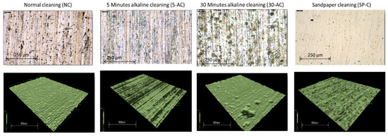
Figure 1.
IFM images show the profile of the four surface preparations samples.
3.1.2. Scanning Electron Microscopy (SEM)
The SEM images in Figure 2 show the four sample preparations’ morphological surface appearance as follows: the most affected surface was generated by 30 min etching cleaning. The other surface preparation samples show that the surface is not significantly affected. However, the inclusions from the silicate carbides are impeded in the sandpaper sample SP-C preparations’ surface as a result of tribology and friction.
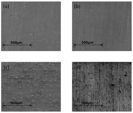
Figure 2.
SEM images showing the surface for (a) NC, (b) 5-AC, (c) 30-AC and (d) SP-C surface preparation samples.
3.1.3. X-ray Powder Diffraction (XRD)
Generally, Figure 3 show there was no significant phase transformation on the surface of the alloy for the four different sample preparations. However, the sandpaper shows fewer aluminium-oxides Al2O3 at 38.4°, which show the level of the oxide on the surface is superficial. At the same time, both alkaline etched samples show a higher level.
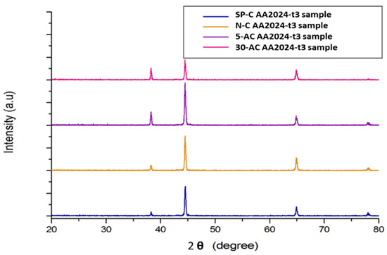
Figure 3.
X-ray diffraction (XRD) reading for the four preparation samples.
3.1.4. Wettability and Contact Angle (WCA)
Figure 4 show the droplets of 10 µL of DI water on the surface of the differently treated samples. It is clear that the highest contact angle was for the 30-AC sample while the smallest was on the sandpaper cleaned sample by 92° and 62°, respectively. This confirms that the 30-AC cleaned sample is less-waitable compared to the others. The contact angles of the 5-AC and NC samples were 72° and 78°, respectively.
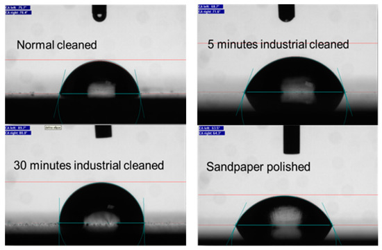
Figure 4.
Water contact angle for NC, SP-C, 5-AC and 30-AC sample.
3.2. Testing Characterisations of Sol-Gel Coated Samples
Electrochemical Impedance Spectroscopy (EIS)
Tests were performed over a period of 6 days. Figure 5a,b show the Bode impedance magnitude plots for sol-gel-NC, sol-gel-SP-C, sol-gel-5-AC and sol-gel-30-AC coated samples at the beginning of the investigation and after 144 h. From Figure 6 it can be seen that the overall impedance for the sol-gel coated samples in the first hour lacked variance between 5.2 × 10⁶ to 3.2 × 10⁶ Ohms/cm2. The maximum reading was with sol-gel-SP-C, and the minimum was for the sol-gel-30-AC; the reading for sol-gel-5-AC and sol-gel-NC was 4.5 × 10⁶ and 4.02 × 10⁶ ohms/cm2, respectively.
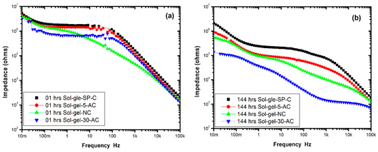
Figure 5.
Bode impedance magnitude plots for sol-gel-NC, sol-gel-SP-C, sol-gel-5-AC and sol-gel-30-AC coated samples in the first hour (a) and after 144 h (b).
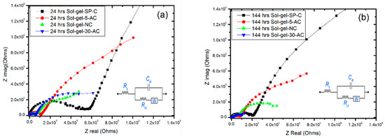
Figure 6.
Nyquist plots for sol-gel-NC, sol-gel-SP-C, sol-gel-5-AC and sol-gel-30-AC coated samples in 24 h (a) and after 144 h (b).
After 144 h, the drop in impedance was clearly apparent by approximately one order of magnitude for the sol-gel-30-AC sample compared to the sol-gel-SP-C sample. This could be due to the microcracks in the sol-gel coating on the 30 min etched samples, also in addition to the oxide film that reduces the adhesion of the sol-gel film on the surface.
On the other hand, the significance reading of the sol-gel-5-AC displayed similar behavior to the sandpaper prepared coated sample but with a slight drop in impedance to reach 1.01 × 10⁶ ohms/cm2, followed by the standard cleaning sample (degreasing only).
Figure 6a,b show the Nyquist plotting for the four sol-gel coated samples during the first 24 h, and after 144 h. All Nyquist plots support the Bode plots as they display one time-constant capacitive behaviour with the Wurburg diffusion element. However, the maximum impedance was for the sol-gel-SP-C coated sample, while the minimum was for sol-gel-30-AC.
4. Conclusions
Mechanical cleaning using abrasive paper produces a smooth surface with good wettability and adhesion for sol-gel. However, there are probably abrasive particles embedded in the surface, which may cause future corrosion to occur. Longer immersion times (30 min) in 10% Super bee® appear to be less optimal as wettability is decreased, possibly due to excessive surface roughening, while the more active surface results in greater oxidation. On the other hand, 5 min immersion in 10% Super bee® gives good wettability and a degree of surface roughening, which may benefit coating adhesion, as well as the degreasing process. Generally, the sol-gel coating can provide excellent protection against corrosion for the mentioned samples depending on the manner of the surface cleaning process; it is clear from the electrochemical testing that the mechanical sandpaper cleaning was a good combination and offered excellent protection. However, due to the time and cost of this process, the 5 min of etching cleaning was acceptable for sol-gel sample preparation, with the lowest results being provided by the degreasing preparation process.
Author Contributions
Conceptualisation, M.H.M.; methodology, M.H.M., O.L. and N.F.; validation and testing M.H.M.; data analysis, M.H.M., N.F. and O.L.; XRD-support analysis, M.H.M.; investigation and revalidation M.H.M.; resources, M.H.M., O.L. and N.F.; writing—original draft preparation, M.H.M.; writing—review and editing, M.H.M., O.L. and N.F.; project supervision, N.F. and O.L. All authors have read and agreed to the published version of the manuscript.
Funding
This research has no assigned direct fund.
Institutional Review Board Statement
Not applicable.
Informed Consent Statement
Not applicable.
Data Availability Statement
The data are not publicly available; the files are stored on corresponding instruments and personal computers.
Acknowledgments
The authors would like to acknowledge the facilitating support provided by Sheffield Hallam University in the Material and Engineering research institute (MERI) and also to the Libyan Scholarship Program for the financial support.
Conflicts of Interest
The authors declare no conflict of interest.
References
- Mussa, M. Development of Hybrid Sol-Gel Coatings on AA2024-T3 with Environmentally Benign Corrosion Inhibitors. Ph.D. Thesis, Sheffield Hallam University, Sheffield, UK, 2020. [Google Scholar]
- Mussa, M.H.; Rahaq, Y.; Takita, S.; Farmilo, N. Study the Enhancement on Corrosion Protection by Adding PFDTES to Hybrid Sol-Gel on AA2024-T3 Alloy in 3.5% NaCl Solutions. Albahit J. Appl. Sci. 2021, 2, 61–68. [Google Scholar]
- Hughes, A.E.; Taylor, R.J.; Nelson, K.J.H.; Hinton, B.R.W.; Wilson, L. Characterisation of surface preparation of 2024 aluminium alloy for conversion coating. Mater. Sci. Technol. 1996, 12, 928–936. [Google Scholar] [CrossRef]
- ASTM International. Standard Practice for Inspection of Marine Surface Preparation and Coating Application; F941–99; American National Standards Institute: Washington, DC, USA, 2009. [Google Scholar]
- Detty, M.R.; Ciriminna, R.; Bright, F.V.; Pagliaro, M. Environmentally benign sol-gel antifouling and foul-releasing coatings. Acc. Chem. Res. 2014, 47, 678–687. [Google Scholar] [CrossRef] [PubMed]
- Akid, R.; Wang, H.; Gobara, M.; Smith, T.J.; Gittens, J. Green coatings for industrial applications. Corros. Manag. 2011, 100, 11–14. [Google Scholar]
- Wang, H.; Akid, R.; Gobara, M. Scratch-resistant anticorrosion sol-gel coating for the protection of AZ31 magnesium alloy via a low temperature sol-gel route. Corros. Sci. 2010, 52, 2565–2570. [Google Scholar] [CrossRef]
- Chen, S.; Li, L.; Zhao, C.; Zheng, J. Surface hydration: Principles and applications toward low-fouling/nonfouling biomaterials. Polymer 2010, 51, 5283–5293. [Google Scholar] [CrossRef] [Green Version]
- Eduok, U.; Suleiman, R.; Gittens, J.; Khaled, M.; Smith, T.J.; Akid, R.; El Ali, B.; Khalil, A. Anticorrosion/antifouling properties of bacterial spore-loaded sol-gel type coating for mild steel in saline marine condition: A case of thermophilic strain of Bacillus licheniformis. RSC Adv. 2015, 5, 93818–93830. [Google Scholar] [CrossRef] [Green Version]
- Lev, O.; Wu, Z.; Bharathi, S.; Glezer, V.; Modestov, A.; Gun, J.; Rabinovich, L.; Sampath, S. Sol−Gel Materials in Electrochemistry. Chem. Mater. 1997, 9, 2354–2375. [Google Scholar] [CrossRef]
- Wang, D.; Bierwagen, G.P. Sol-gel coatings on metals for corrosion protection. Prog. Org. Coatings 2009, 64, 327–338. [Google Scholar] [CrossRef]
- Pathak, S.S.; Khanna, S. Sol-gel nano coatings for corrosion protection. Met. Surf. Eng. 2012, 12, 304–329. [Google Scholar]
- Rahaq, Y.; Mussa, M.; Mohammad, A.; Wang, H.; Hassan, A. Highly reproducible perovskite solar cells via controlling the morphologies of the perovskite thin films by the solution-processed two-step method. J. Mater. Sci. Mater. Electron. 2018, 29, 16426–16436. [Google Scholar] [CrossRef] [Green Version]
- Bracco, G.; Holst, B. Contact Angle andWetting Properties. In Springer Series in Surface Sciences; Springer: New York, NY, USA, 2013; Volume 51, ISBN 978-3-642-34242-4. [Google Scholar]
- Tait, W.S. Electrochemical Impedance Spectroscopy Fundamentals, an Introduction to Electrochemical Corrosion Testing for Practicing Engineers and Scientists; Tait, W.S., Ed.; PairODocs Publications: Racine, WI, USA, 1994; ISBN 13-978-0966020700. [Google Scholar]
Publisher’s Note: MDPI stays neutral with regard to jurisdictional claims in published maps and institutional affiliations. |
© 2021 by the authors. Licensee MDPI, Basel, Switzerland. This article is an open access article distributed under the terms and conditions of the Creative Commons Attribution (CC BY) license (https://creativecommons.org/licenses/by/4.0/).