
A Functional Model Printing Approach Optimized for Cost-Efficiency Using FDM Technology †


Abstract
1. Introduction
2. Materials and Methods
2.1. Analysis Parameters
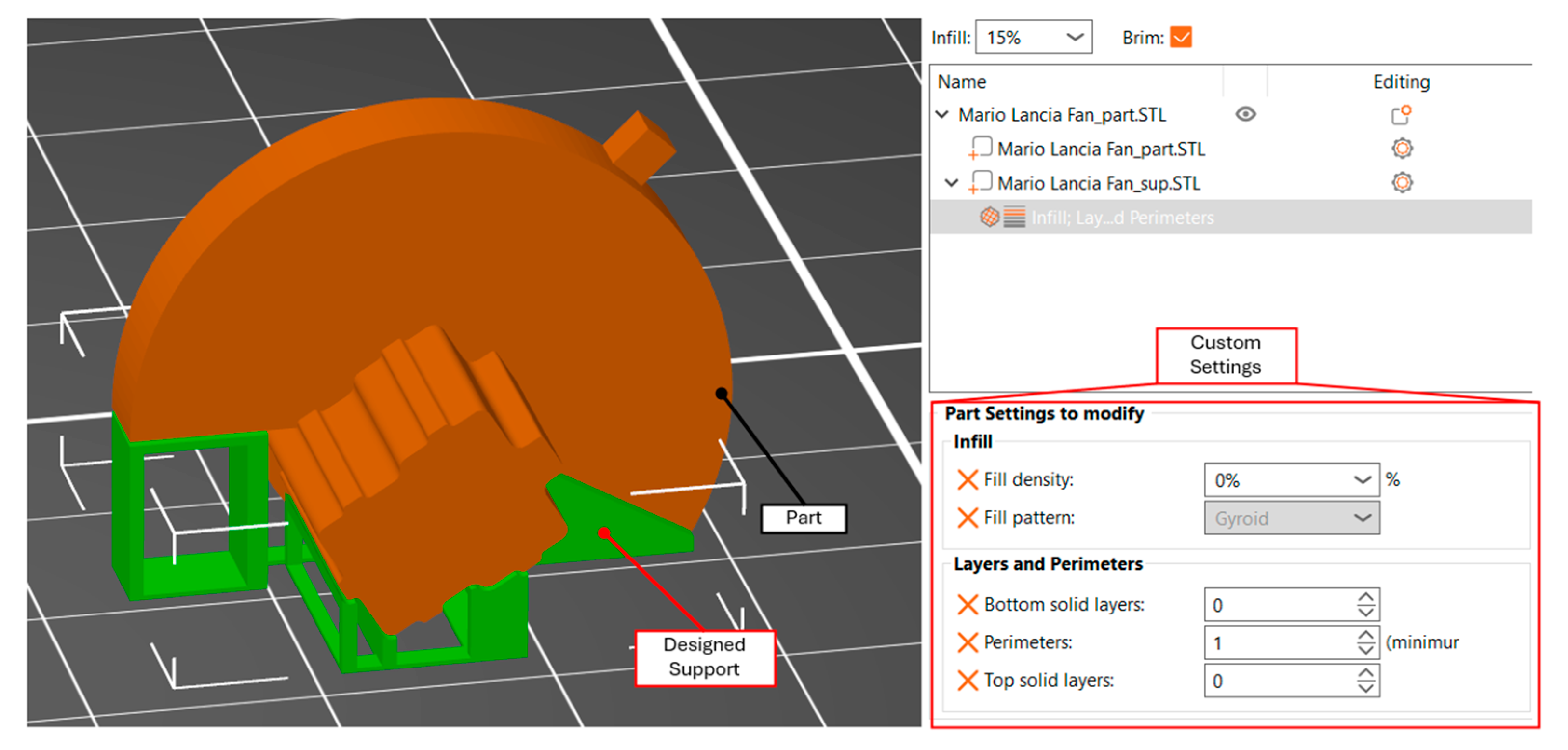
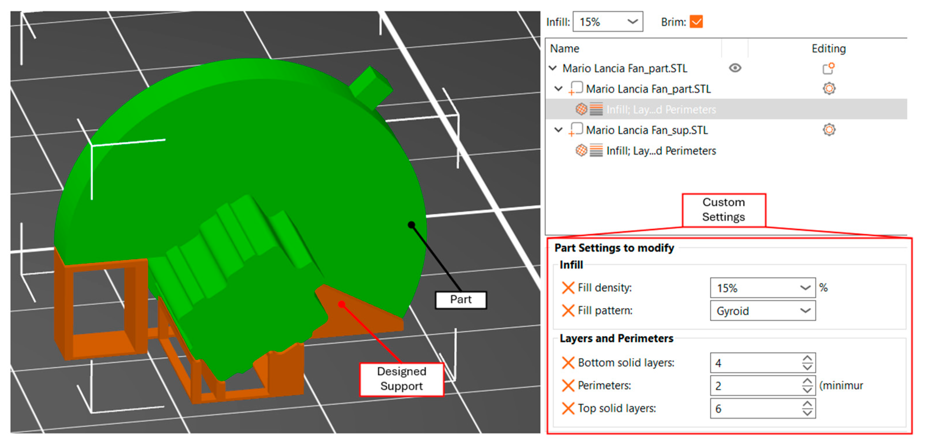
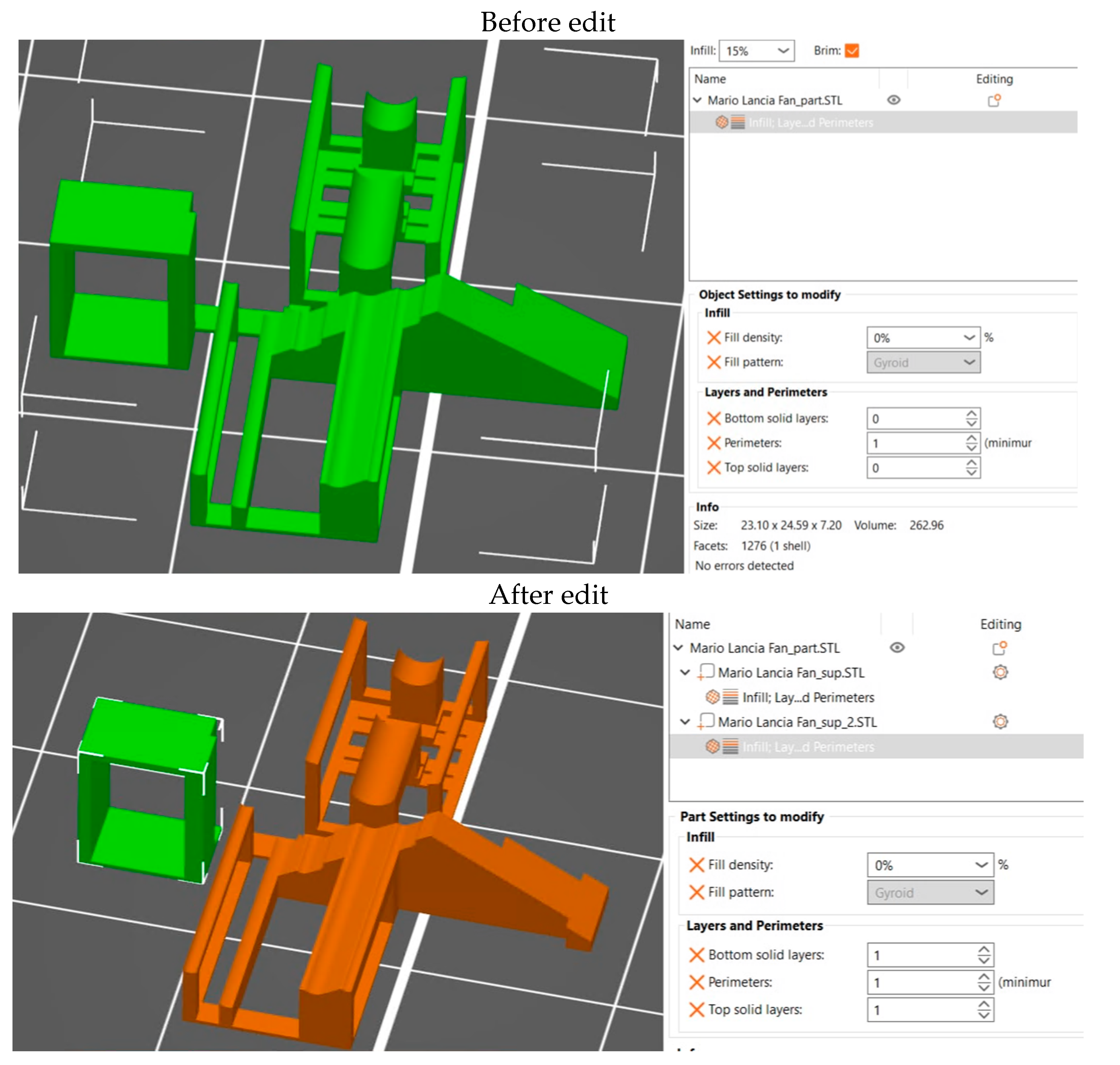
2.2. Methodology
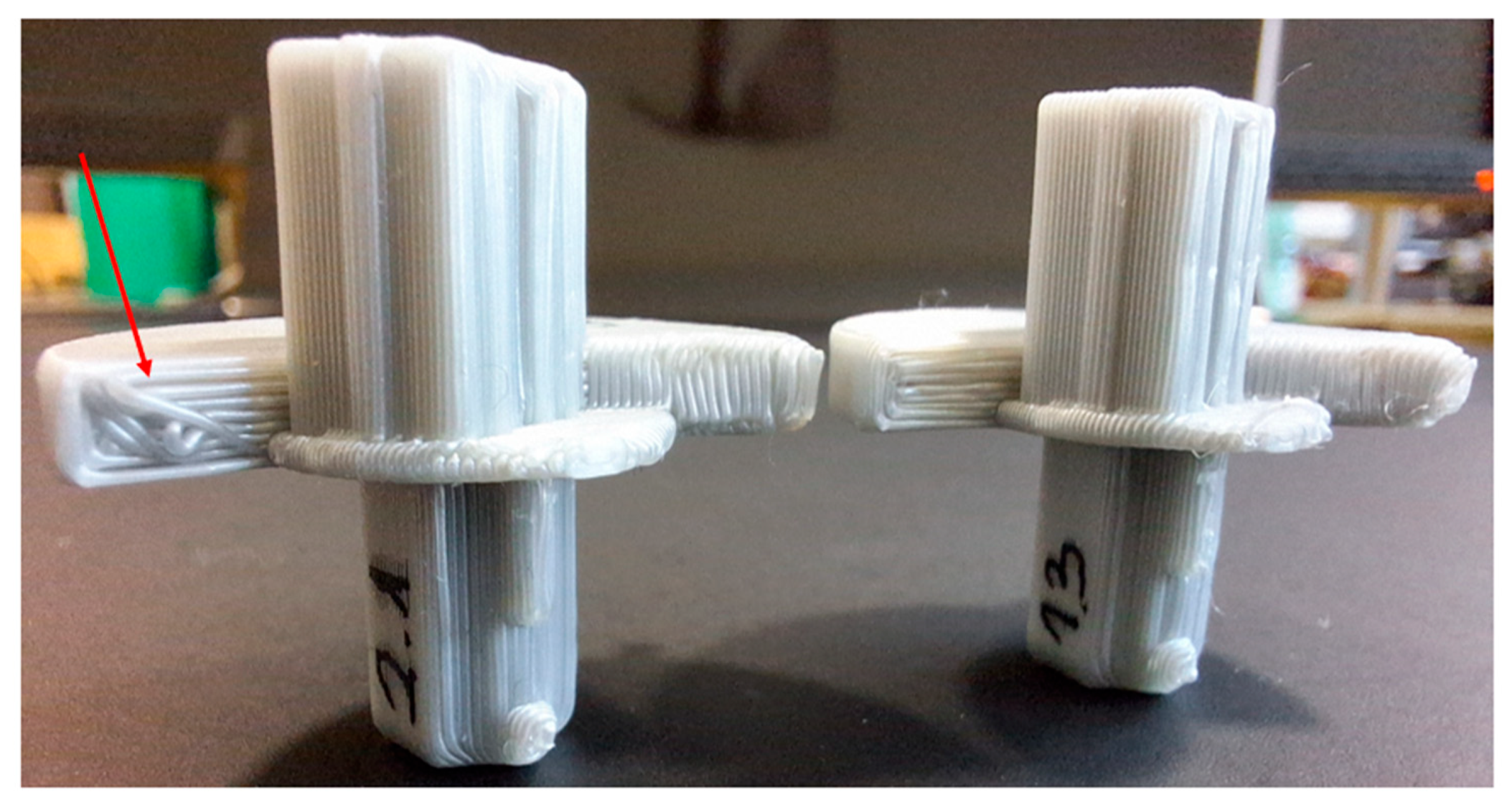
3. Results
4. Discussion
5. Conclusions
Author Contributions
Funding
Institutional Review Board Statement
Informed Consent Statement
Data Availability Statement
Conflicts of Interest
References
- Cano-Vicent, A.; Tambuwala, M.M.; Hassan, S.S.; Barh, D.; Aljabali, A.A.; Birkett, M.; Arjunan, A.; Serrano-Aroca, Á. Fused Deposition Modelling: Current Status, Methodology, Applications and Future Prospects. Addit. Manuf. 2021, 47, 102378. [Google Scholar] [CrossRef]
- Antonova, M.; Antonov, S. Most Applicable Hardware Technologies and Materials for Physical Prototyping. In MATTEH 2024 Conference Proceeding, Proceedings of the International Scientific Conference MATTEX 2024, Shumen, Bulgaria, 24–26 October 2024; Konstantin Preslavsky University of Shumen: Shumen, Bulgaria, 2024; Volume 2, pp. 344–349. [Google Scholar] [CrossRef]
- Dochev, B.; Dimova, D.; Zagorski, M.; Kasabov, P.; Chuchulska, B. Investigation of the influence of the manufacturing process on the structure of hypereutectic aluminium-silicon alloys. ETR 2024, 3, 53–57. [Google Scholar] [CrossRef]
- Patil, P.; Singh, D.; Raykar, S.J.; Bhamu, J. Multi-Objective Optimization of Process Parameters of Fused Deposition Modeling (FDM) for Printing Polylactic Acid (PLA) Polymer Components. Mater. Today Proc. 2021, 45, 4880–4885. [Google Scholar] [CrossRef]
- Todorov, G.; Kamberov, K.; Vasilev, H.; Ivanov, T. Design Variants Assessment Of Street LED Device Based On Virtual Prototyping. In Proceedings of the 17th Conference on Electrical Machines, Drives and Power Systems (ELMA), Sofia, Bulgaria, 1–4 July 2021; pp. 1–4. [Google Scholar] [CrossRef]
- Zhang, Z.; Zhao, M.; Shen, Z.; Wang, Y.; Jia, X.; Yan, D.-M. Interactive Reverse Engineering of CAD Models. Comput. Aided Geom. Des. 2024, 111, 102339. [Google Scholar] [CrossRef]
- Kantaros, A.; Ganetsos, T.; Petrescu, F.; Ungureanu, L.; Munteanu, I. Post-Production Finishing Processes Utilized in 3D Printing Technologies. Processes 2024, 12, 595. [Google Scholar] [CrossRef]
- Zhang, G.; Li, J.; Zhou, X.; Wang, A. Optimization design of support structure based on 3D printing technology. Sci. Rep. 2024, 14, 18225. [Google Scholar] [CrossRef] [PubMed]
- Efa, D.A.; Ifa, D.A. Optimization of Design Parameters and 3D-Printing Orientation to Enhance the Efficiency of Topology-Optimized Components in Additive Manufacturing. Results Mater. 2025, 26, 100702. [Google Scholar] [CrossRef]
- Antonov, S. CAD/CAM/CAE Systems and Artificial Intelligence to Help Design Components for Personal Ballistic Protection Equipment. Annu. Konstantin Preslavski Univ. Shumen 2023, XIII, 262–268. [Google Scholar]
- Jin, Q.; Ma, C.; Zhu, Y. Self-Generating Multiscale Configurations, Their CAD Features in Support of 3D Printing and Their CAE Efficiencies. Addit. Manuf. 2025, 99, 104670. [Google Scholar] [CrossRef]
- Arobli, M.; Taghizadieh, N.; Yaghmaei-Sabegh, S.; Azar, S.Z. Optimizing Additive Manufacturing: Minimizing Support Structures through Constraint-Based Design. Structures 2024, 63, 106379. [Google Scholar] [CrossRef]
- May, G.; Psarommatis, F. Maximizing Energy Efficiency in Additive Manufacturing: A Review and Framework for Future Research. Energies 2023, 16, 4179. [Google Scholar] [CrossRef]
- Shin, S.; Goh, B.; Oh, Y.; Chung, H. Topology Optimization for Multi-Axis Additive Manufacturing Considering Overhang and Anisotropy. arXiv 2025, arXiv:2502.20343. [Google Scholar] [CrossRef]
- Zagorski, M.; Sofronov, Y.; Ivanova, D.; Dimova, K. Investigation of Different FDM/FFF 3D Printing Methods for Improving the Surface Quality of 3D Printed Parts. In Proceedings of the 10th International Scientific Conference “TechSys 2021”—Engineering, Technologies and Systems, Plovdiv, Bulgaria, 27–29 May 2021. [Google Scholar] [CrossRef]
- Ng, N.Y.Z.; Abdul Haq, R.H.; Marwah, O.M.F.; Ho, F.H.; Adzila, S. Optimization of Polyvinyl Alcohol (PVA) Support Parameters for Fused Deposition Modelling (FDM) by Using Design of Experiments (DOE). Mater. Today Proc. 2022, 57, 1226–1234. [Google Scholar] [CrossRef]
- Kothandaraman, L.; Balasubramanian, N.K. Optimization of FDM printing parameters for square lattice structures: Improving mechanical characteristics. Mater. Today Proc. 2024, in press. [Google Scholar] [CrossRef]
- Sandhu, G.S.; Sandhu, K.S.; Boparai, K.S. Effect of extrudate geometry on surface finish of FDM printed ABS parts. Mater. Today Proc. 2024, in press. [Google Scholar] [CrossRef]
- Le, L.; Rabsatt, M.A.; Eisazadeh, H.; Torabizadeh, M. Reducing Print Time While Minimizing Loss in Mechanical Properties in Consumer FDM Parts. Int. J. Lightweight Mater. Manuf. 2022, 5, 197–212. [Google Scholar] [CrossRef]
- Mani, M.; Karthikeyan, A.G.; Kalaiselvan, K.; Muthusamy, P.; Muruganandhan, P. Optimization of FDM 3-D Printer Process Parameters for Surface Roughness and Mechanical Properties Using PLA Material. Mater. Today Proc. 2022, 66, 1926–1931. [Google Scholar] [CrossRef]
- Sahoo, S.; Sutar, H.; Senapati, P.; Shankar Mohanto, B.; Ranjan Dhal, P.; Kumar Baral, S. Experimental Investigation and Optimization of the FDM Process Using PLA. Mater. Today Proc. 2023, 74, 843–847. [Google Scholar] [CrossRef]
- Moradi, M.; Sheikhmohammad Meiabadi, M.S.; Siddique, U.; Salimi, N.; Farahani, S. Circular Economy-Driven Repair of 3D Printed Polylactic Acid (PLA) by Fused Deposition Modelling (FDM) through Statistical Approach. Mater. Today Commun. 2025, 42, 111264. [Google Scholar] [CrossRef]


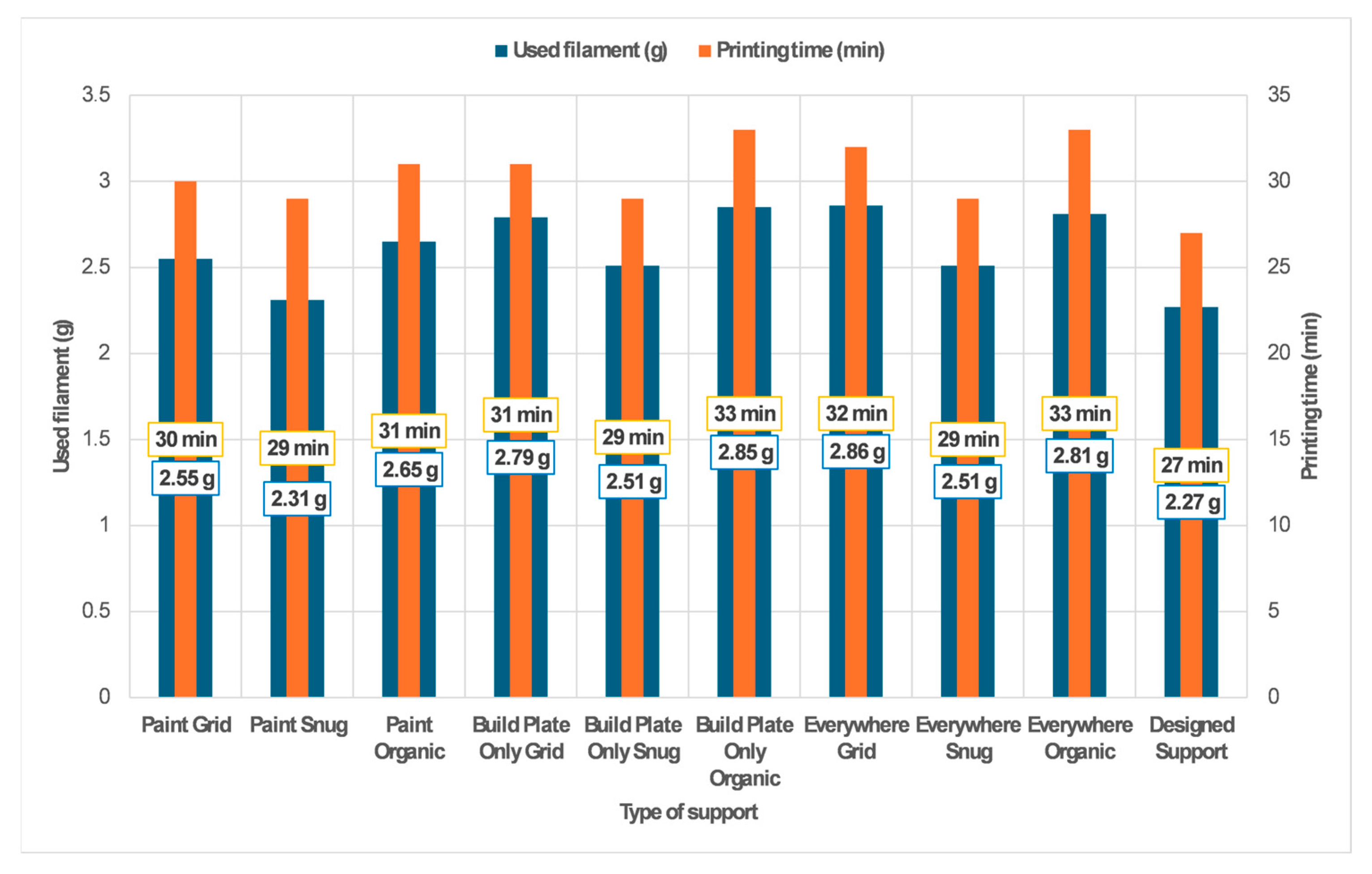
| Type of Support | Used Filament (g) | Printing Time (min) |
|---|---|---|
| Paint Grid | 2.55 | 30 |
| Paint Snug | 2.31 | 29 |
| Paint Organic | 2.65 | 31 |
| Build Plate Only Grid | 2.79 | 31 |
| Build Plate Only Snug | 2.51 | 29 |
| Build Plate Only Organic | 2.85 | 33 |
| Everywhere Grid | 2.86 | 32 |
| Everywhere Snug | 2.51 | 29 |
| Everywhere Organic | 2.81 | 33 |
| Designed Support | 2.27 | 27 |
Disclaimer/Publisher’s Note: The statements, opinions and data contained in all publications are solely those of the individual author(s) and contributor(s) and not of MDPI and/or the editor(s). MDPI and/or the editor(s) disclaim responsibility for any injury to people or property resulting from any ideas, methods, instructions or products referred to in the content. |
© 2025 by the authors. Licensee MDPI, Basel, Switzerland. This article is an open access article distributed under the terms and conditions of the Creative Commons Attribution (CC BY) license (https://creativecommons.org/licenses/by/4.0/).
Share and Cite
Bankov, B.; Todorov, T.T.; Todorov, G. A Functional Model Printing Approach Optimized for Cost-Efficiency Using FDM Technology. Eng. Proc. 2025, 100, 53. https://doi.org/10.3390/engproc2025100053
Bankov B, Todorov TT, Todorov G. A Functional Model Printing Approach Optimized for Cost-Efficiency Using FDM Technology. Engineering Proceedings. 2025; 100(1):53. https://doi.org/10.3390/engproc2025100053
Chicago/Turabian StyleBankov, Blagovest, Todor T. Todorov, and Georgi Todorov. 2025. "A Functional Model Printing Approach Optimized for Cost-Efficiency Using FDM Technology" Engineering Proceedings 100, no. 1: 53. https://doi.org/10.3390/engproc2025100053
APA StyleBankov, B., Todorov, T. T., & Todorov, G. (2025). A Functional Model Printing Approach Optimized for Cost-Efficiency Using FDM Technology. Engineering Proceedings, 100(1), 53. https://doi.org/10.3390/engproc2025100053