
A Comparative Study of Vibrations in Front Suspension Components Using Bushings Made from Different Materials †

Abstract
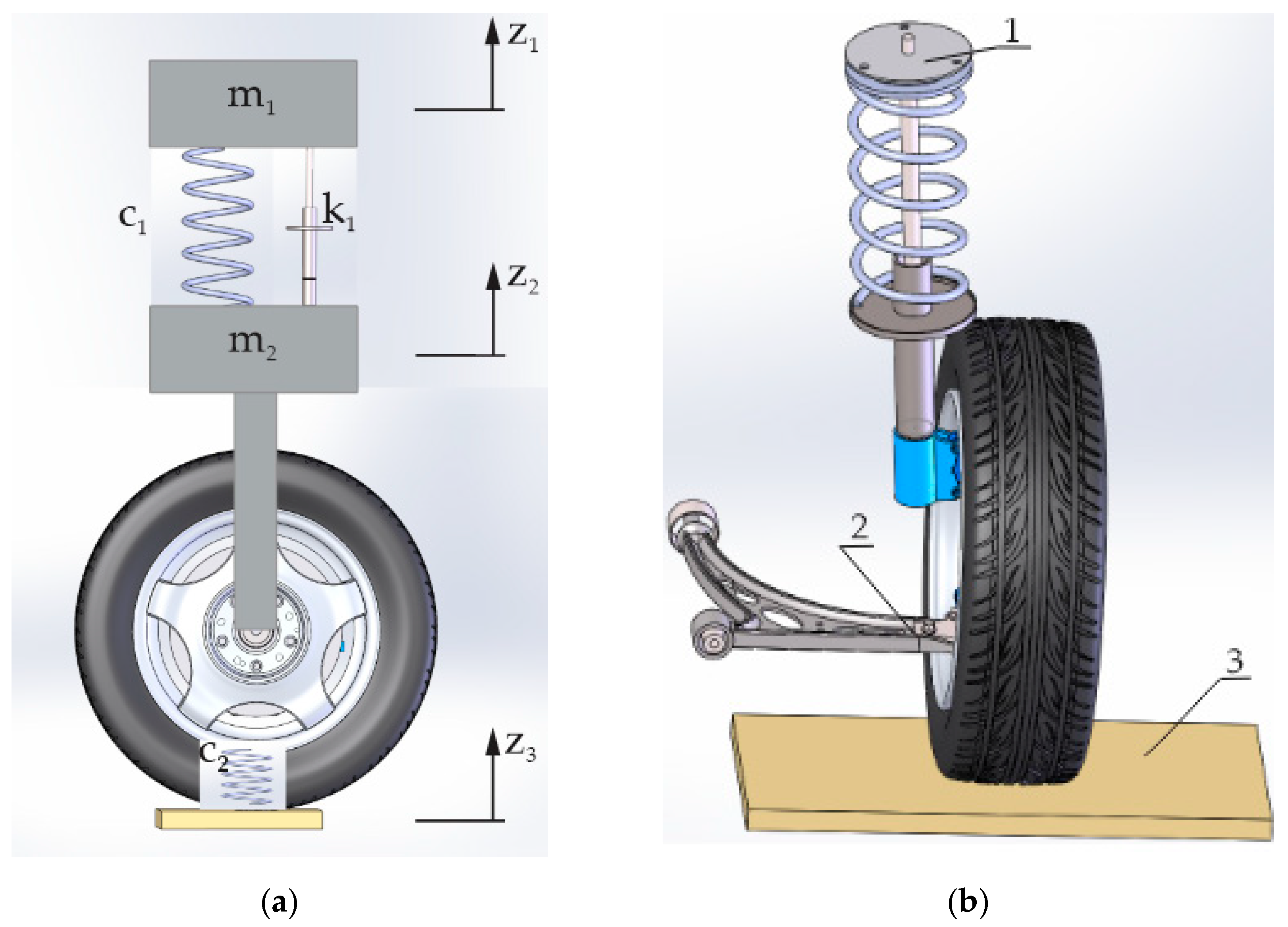
1. Introduction
2. Materials and Methods
- -
- The car is placed on the suspension tester; initially, the arm is with the original bushings;
- -
- The sensors of the measuring system are installed;
- -
- The wheels of the front axle are positioned on the tester platforms;
- -
- The test is started;
- -
- The accelerations are measured on the platform, on the arm and on the body of the strut, and this is carried out several times for different tyre pressures;
- -
- After replacing one of the rubber bushings in the arm with a polyurethane one, the measurements are repeated under the same conditions and in the same sequence.
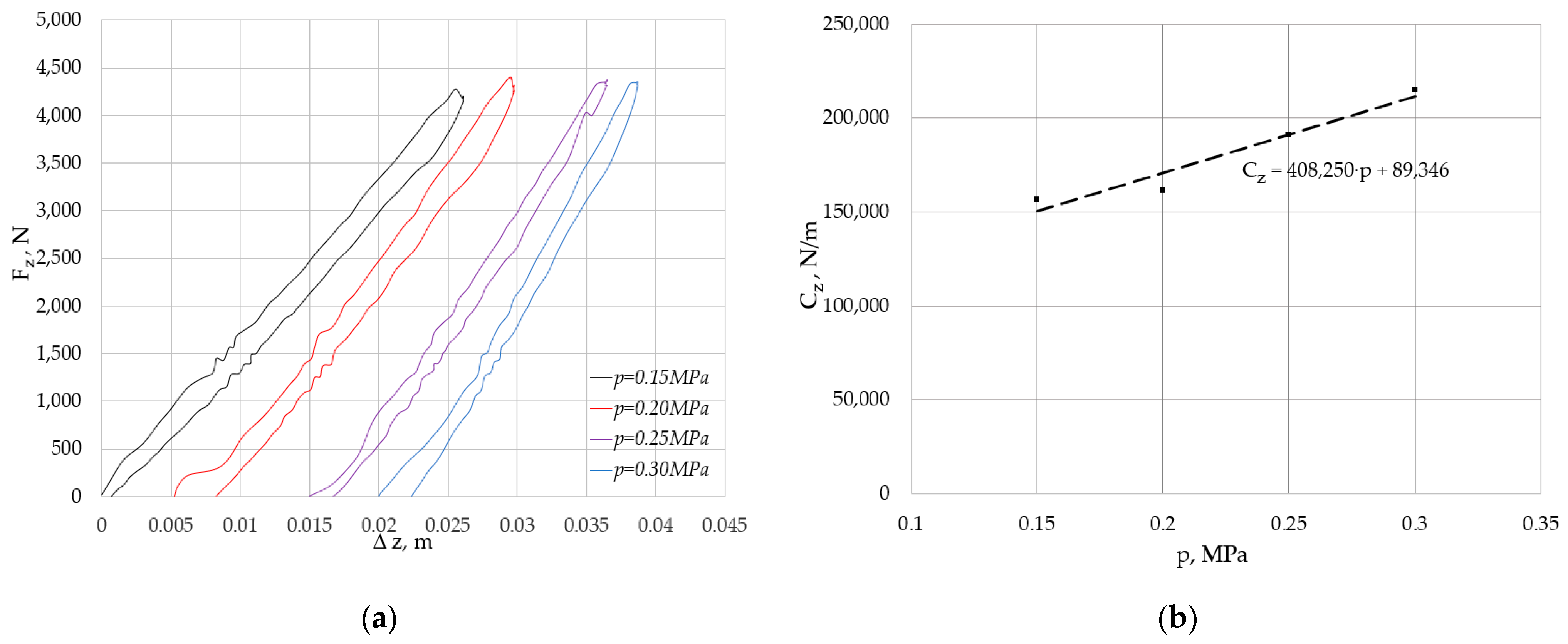
3. Results and Discussion
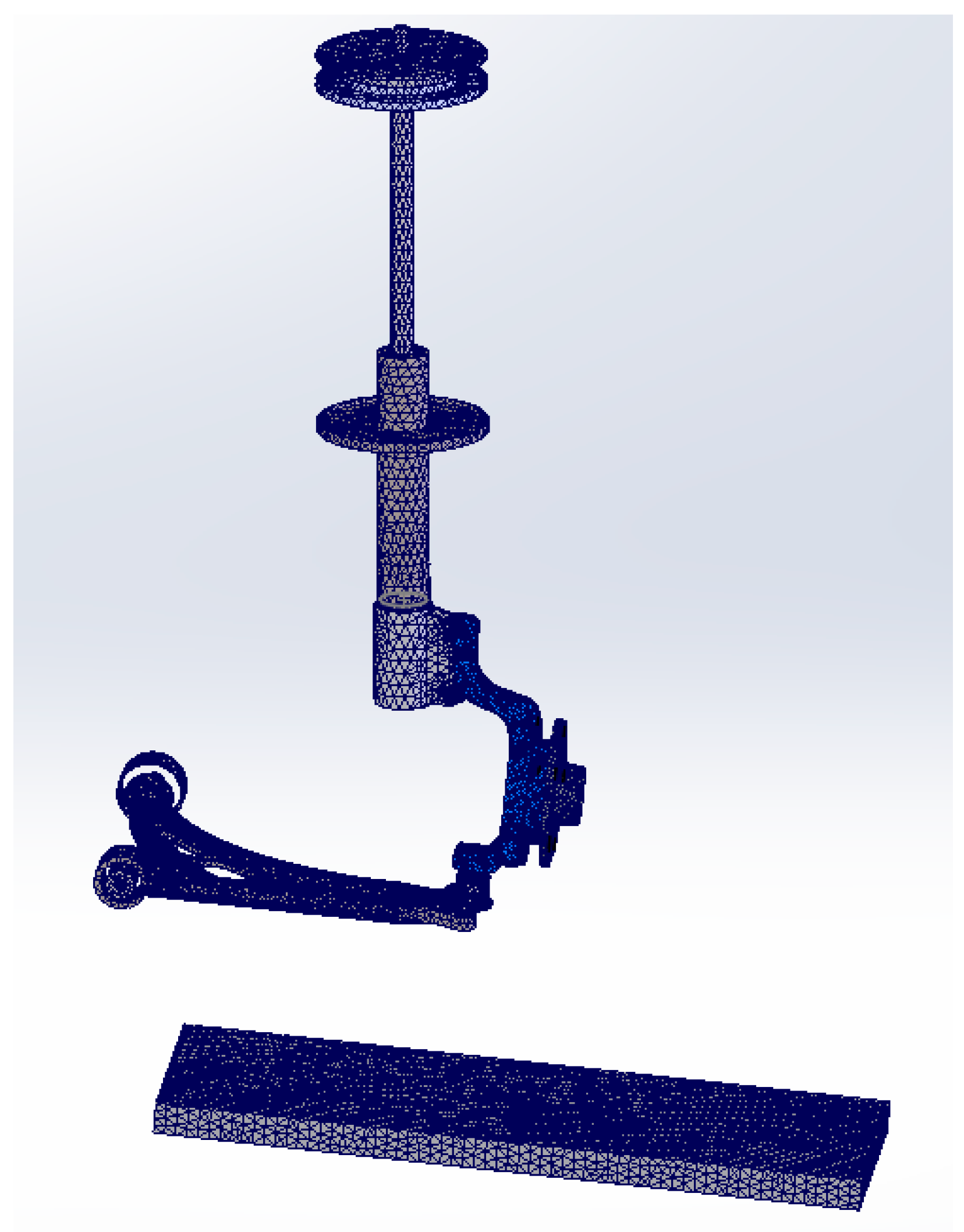
3.1. Simulation Results
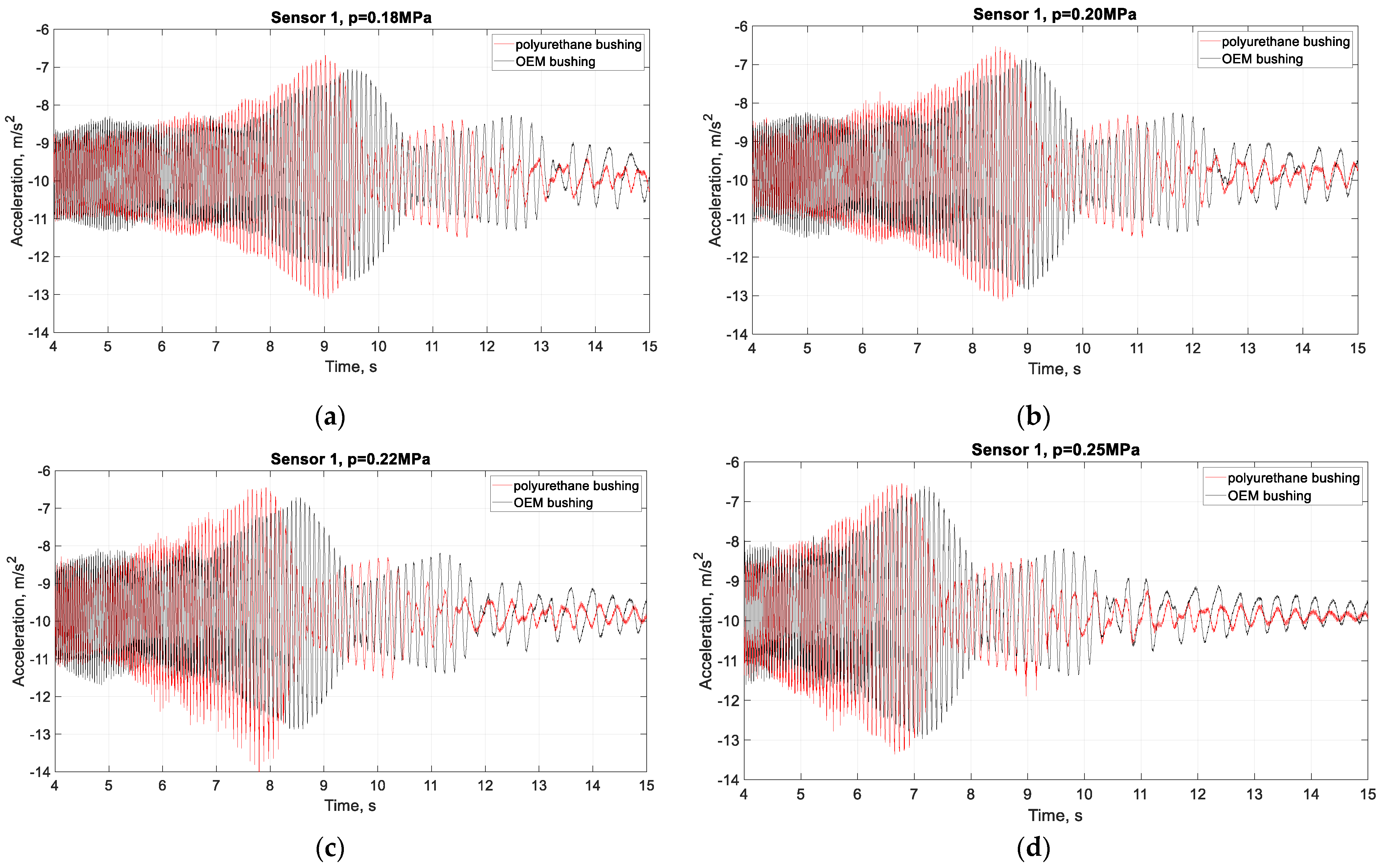
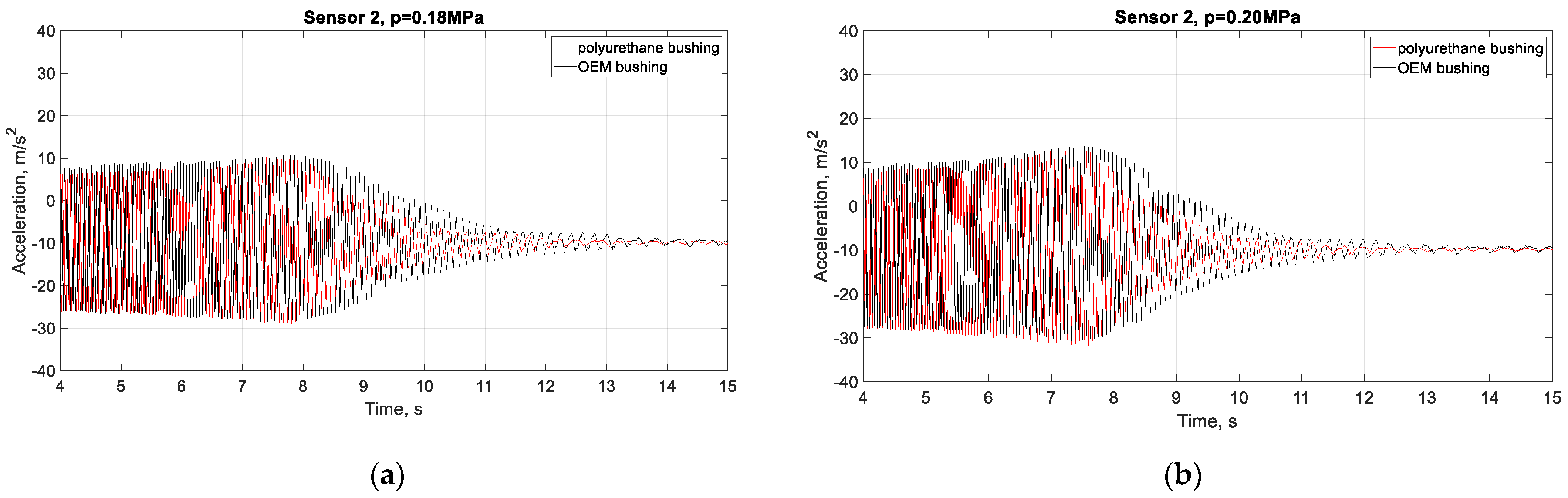
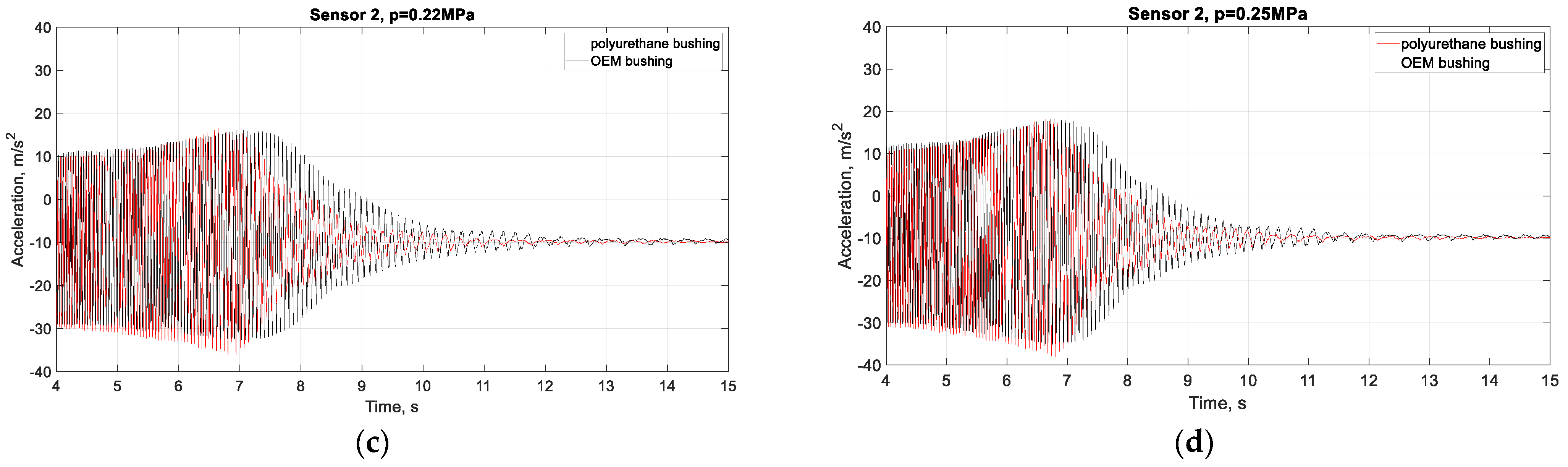
3.2. Experimental Results
4. Conclusions
- -
- The acceleration results of sensors 1 and 2 obtained using numerical analysis have comparable values to those obtained from the experiment, and the results by FEA can be used to refine the methodology.
- -
- The maximum acceleration value of sensor 1, mounted on the body of the strut, is around 3 m/s2 at tyre pressures of 0.22MPa when the rubber bushings are mounted in the arm. When rubber bushing and polyurethane bushing are used, the acceleration is around 3.6 m/s2 at tyre pressures of 0.22 MPa.
- -
- The amplitude of the acceleration values of sensors 1 and 2 increases with increasing tyre pressure.
- -
- A significant difference in values and type of the accelerations curve is observed in sensor 1, mounted on the body of the strut.
- -
- -
- After replacing one of the rubber bushings on the arm with a polyurethane one, damping occurs faster, which is a prerequisite for slower wear, and therefore for greater durability and endurance under higher loads. This is due to the different material properties of the polyurethane and rubber.
Author Contributions
Funding
Institutional Review Board Statement
Informed Consent Statement
Data Availability Statement
Conflicts of Interest
References
- Dehbari, S.; Marzbanrad, J. Kinematic and Dynamic Analysis for a New MacPherson Strut Suspension System. Sci. J. Mech. Mech. Eng. 2018, 22, 1223–1238. [Google Scholar] [CrossRef]
- Aye, Y.; Win, H.; Swe, M.; Lat, K. Vibration Analysis of Suspension System for 3DOF Quarter Car Model with Tire Damping. Int. J. Mech. Eng. Robot. Res. 2024, 13, 196–204. [Google Scholar] [CrossRef]
- Barethiye, V.; Pohit, G.; Mitra, A. A combined nonlinear and hysteresis model of shock absorber for quarter car simulation on the basis of experimental data. Eng. Sci. Technol. Int. J. 2017, 20, 1610–1622. [Google Scholar] [CrossRef]
- Sathishkumar, P.; Jancirani, J.; Dennie, J.; Manikandan, S. Mathematical modelling and simulation quarter car vehicle suspension. Int. J. Innov. Res. Sci. Eng. Technol. 2014, 3, 2347–6710. [Google Scholar]
- Uddin, N. Optimal Control Design of Active Suspension System Based on Quarter Car Model. J. Infotel Inform.-Telecommun.-Electron. Website J. 2019, 11, 55–61. [Google Scholar] [CrossRef]
- Paliwal, R.; Shrivastava, R. Design and FEA Simulation of Vehicle Suspension System by Using ANSYS. Smart Moves J. Ijoscience 2021, 7, 32–41. [Google Scholar] [CrossRef]
- Burdzik, R.; Konieczny, Ł. Vibration issues in passenger car. Int. Sci. J. Transp. Probl. 2014, 9, 83–90. [Google Scholar]
- Szczypinski-Sala, W.; Kot, A.; Hankus, M. The Evaluation of Vehicle Vibrations Excited with a Test Plate during Technical Inspection of Vehicle Suspension. J. Appl. Sci. 2023, 13, 11. [Google Scholar] [CrossRef]
- Marinescu, C.; Castravete, C.; Dumitru, N. Vibration study of a vehicle suspension assembly with the finite element method. IOP Conf. Ser. Mater. Sci. Eng. 2017, 252, 012030. [Google Scholar] [CrossRef]
- Yu, C.; Chiu, C. Ride responses of MacPherson suspension systems. In Proceedings of the 2nd International Conference on Precision Machinery and Manufacturing Technology, Kending, Taiwan, 9–21 May 2017. [Google Scholar] [CrossRef]
- Chávez Conde, E.; Beltrán Carbaja, F.; Valderrábano González, A.; Favela Contreras, A. Active vibration control of vehicle suspension systems using sliding modes, differential flatness and generalized proportional-integral control. Rev. Fac. De Ing. Univ. De Antioquia 2011, 61, 104–113. [Google Scholar] [CrossRef]
- Genov, J. Multi-criteria synthesis of frequency-modulated discrete control of semi-active vehicle suspension—Part 1: Analysis and control strategies. In Proceedings of the 8th International Scientific Conference “TechSys 2019”—Engineering, Technologies and Systems, Plovdiv, Bulgaria, 16–18 May 2019. [Google Scholar] [CrossRef]
- Sinapov, P.; Kralov, I.; Polihronov, G.; Ignatov, I.; Nedelchev, K. Experimental Study and Analysis of the Vehicle Self-Excited Friction Vibrations During Set-off. In Proceedings of the Scientific Conference on Aeronautics, Automotive and Railway Engineering and Technologies “BulTrans-2011”, Sozopol, Bulgaria, 27–30 September 2011; pp. 263–266. [Google Scholar]
- Georgiev, Z.; Kunchev, L. Study of the vibrational behaviour of the components of a car suspension. In Proceedings of the 10th International Scientific Conference on Aeronautics, Automotive and Railway Engineering and Technologies, “BulTrans-2018”, Sozopol, Bulgaria, 15–17 September 2018. [Google Scholar] [CrossRef]
- Kunchev, L.; Georgiev, Z. Experimental and Model Study of high Frequency oscillations in suspension components. In Proceedings of the 23rd International Scientific Conference, Transport Means (2019), Palanga, Lithuania, 2–4 October 2019; pp. 387–392. [Google Scholar]
- Georgiev, Z.; Kunchev, L. Study of the stresses in the front suspension components of a car passing over speed breakers. In Proceedings of the Scientific Conference on Aeronautics, Automotive and Railway Engineering and Technologies “BulTrans 2019”, Sozopol, Bulgaria, 10–12 September 2019. [Google Scholar] [CrossRef]
- Iontchev, E.; Damyanov, I.; Simeonov, I.; Miletiev, R. Inertial system for measurement of the dynamic response and status of the vehicle suspension elements. In Proceedings of the 3rd International Conference on Digital Information Processing and Communications, ICDIPC (2013) 122220, Dubai, United Arab Emirates, 30 January–1 February 2013; pp. 331–336. Available online: https://www.scopus.com/record/display.uri?eid=2-s2.0-84978717707&origin=resultslist (accessed on 12 May 2025).
- Duleba, B.; Greškovič, F.; Jachowicz, T. Possibility of manufacturing of race polyurethane bushings using rapid prototyping and prototype molds. Transf. Inovácií 2012, 24, 195–199. [Google Scholar]
- Ambarev, K.; Taneva, S. Comparison of vibrations in MacPherson suspension type components with different characteristics of vibration isolators. In Proceedings of the Youth Forums “Science, Technology, Innovation, Business” 2024, Plovdiv, Bulgaria, 21–22 November 2024; pp. 251–255, ISSN 2367-8569. [Google Scholar]
- Taneva, S.; Ambarev, K. Study of the Vibrations of MacPherson Suspension Components. In Proceedings of the 13th International Scientific Conference “TechSys 2024”—Engineering, Technologies and Systems, Plovdiv, Bulgaria, 16–18 May 2024. [Google Scholar] [CrossRef]
- Taneva, S.; Penchev, S.; Ambarev, K. Stiffness Analysis of the Rubber Bushings of MacPherson and Double Wishbone Suspensions. In Proceedings of the 15th International Scientific and Practical Conference Environment. Technology. Resources., Rezekne, Latvia, 27–28 June 2024; Volume I, pp. 358–363. [Google Scholar] [CrossRef]
- Taneva, S.; Penchev, S.; Ambarev, K. Mechanical behavior and stiffness of a polyurethane bushing of a passenger car suspension. In Proceedings of the 15th International Scientific and Practical Conference Environment. Technology. Resources., Rezekne, Latvia, 27–28 June 2024; Volume I, pp. 364–367. [Google Scholar] [CrossRef]
- BDS EN 10293:2005; Steel Castings for General Engineering Uses. Bulgarian Institute for Standardization: Sofia, Bulgaria, 2005.
- BDS EN 10250-3:2022; Open Die Steel Forgings for General Engineering Purposes—Part 3: Alloy Special Steels. Bulgarian Institute for Standardization: Sofia, Bulgaria, 2022.


| Parameters | Arm | Hub, Shrut, Knuckle, Joint |
|---|---|---|
| Density [kg/m3] | 7300 | 7700 |
| Elastic modulus [N/mm2] | 190,000 | 210,000 |
| Poisson’s ratio | 0.26 | 0.28 |
| Parameter | Theoretical (FEM) | Experimental |
|---|---|---|
| Max. acceleration sensor 1, [m/s2] | 2.8 | 3.6 |
| Max. acceleration sensor 2, [m/s2] | 25.3 | 25 |
Disclaimer/Publisher’s Note: The statements, opinions and data contained in all publications are solely those of the individual author(s) and contributor(s) and not of MDPI and/or the editor(s). MDPI and/or the editor(s) disclaim responsibility for any injury to people or property resulting from any ideas, methods, instructions or products referred to in the content. |
© 2025 by the authors. Licensee MDPI, Basel, Switzerland. This article is an open access article distributed under the terms and conditions of the Creative Commons Attribution (CC BY) license (https://creativecommons.org/licenses/by/4.0/).
Share and Cite
Ambarev, K.; Taneva, S. A Comparative Study of Vibrations in Front Suspension Components Using Bushings Made from Different Materials. Eng. Proc. 2025, 100, 42. https://doi.org/10.3390/engproc2025100042
Ambarev K, Taneva S. A Comparative Study of Vibrations in Front Suspension Components Using Bushings Made from Different Materials. Engineering Proceedings. 2025; 100(1):42. https://doi.org/10.3390/engproc2025100042
Chicago/Turabian StyleAmbarev, Krasimir, and Stiliyana Taneva. 2025. "A Comparative Study of Vibrations in Front Suspension Components Using Bushings Made from Different Materials" Engineering Proceedings 100, no. 1: 42. https://doi.org/10.3390/engproc2025100042
APA StyleAmbarev, K., & Taneva, S. (2025). A Comparative Study of Vibrations in Front Suspension Components Using Bushings Made from Different Materials. Engineering Proceedings, 100(1), 42. https://doi.org/10.3390/engproc2025100042