Abstract
The safe transport of cylindrical loads such as metal, paper, or polymer rollers requires specialized securing structures that address the complex dynamic forces encountered during rail movement. This paper presents a structured methodology for the design and verification of such securing systems, combining theoretical analysis, standardized load models, and numerical simulations. The method includes load calculations based on EN 12195-1:2010, EN 15551, and Eurocode 1, and validation through finite element modeling in Ansys Workbench. The proposed structure ensures stability under static and dynamic loads, including acceleration, braking, turning, and wind forces, while optimizing wagon space utilization. Simulation results confirm that the design meets strength and safety criteria without exceeding material stress limits, offering a reliable solution for the secure transport of cylindrical rollers.
1. Introduction
Ensuring the safe and efficient transport of cylindrical loads—such as metal, paper, or polymer rollers—by railway is a critical aspect of modern logistics and industrial practice. The transport of bulky cylindrical objects presents specific challenges due to their geometry, high center of gravity, and propensity to roll or shift if not adequately restrained. Improper securing during rail transport can result in catastrophic incidents, including cargo displacement, wagon derailment, infrastructure damage, and serious safety hazards for operating personnel [1,2].
Although international standards such as EN 12195-1:2010 [3] and ISO 27956:2009 [4] provide general guidance for cargo securing, they are primarily tailored to road transport and are not specifically optimized for the dynamic and complex operational conditions encountered in railway logistics. Similarly, standards like EN 15551:2009 [5] and UIC Code 777-2 [6] outline general securing principles for freight wagons but lack detailed technical solutions for cylindrical or rolling loads under dynamic rail-specific forces. Consequently, the securing of cylindrical objects often relies on traditional methods such as wedges, straps, and friction-enhancing surfaces, which may not provide sufficient resistance under combined static and dynamic loading conditions [7].
Railway transport subjects cargo to a combination of longitudinal (acceleration and braking), transverse (curve negotiation and centrifugal effects), and vertical forces (track irregularities and vibration), all of which act simultaneously and can compromise load stability [8,9]. Experimental studies and operational incident analyses have shown that even relatively small shifts in cylindrical loads during dynamic events can result in progressive movement, increasing the risk of overturning or derailment [10].
Recent advances in numerical modeling, such as multibody dynamics (MBD) and finite element method (FEM) simulations, have improved the ability to predict and mitigate cargo instability under realistic operational scenarios. Multibody simulations, as applied in the dynamic testing of railway vehicles [11], demonstrate that the interaction between wagon dynamics and unsecured or poorly secured loads significantly affects the safety and performance of the transport system [12,13]. Accurate modeling of cargo behavior under dynamic loading is therefore critical for the design and validation of effective securing systems.
Moreover, contemporary engineering research highlights the importance of stress analysis in securing structures. Areas with high stress concentrations, especially around cargo supports and restraint fixtures, are often the initiation points for structural fatigue or failure [14,15]. Methods for reducing stress concentration factors (SCFs)—through improved geometry, material selection, and load distribution—are essential to enhance the long-term reliability of securing structures, particularly under cyclic dynamic loading typical for railway transport [16].
Previous works [17,18] underline that targeted optimization of stress can lead to significant improvements in the fatigue life. Furthermore, studies such as [19,20] emphasize the necessity of integrating dynamic load modeling with structural optimization techniques to ensure both the functional reliability and operational safety of specialized freight securing devices.
In light of these challenges, this paper proposes a systematic methodology for the design and verification of a specialized securing structure intended for the stabilization of cylindrical rollers during railway transport. The methodology integrates the following steps: (i) load analysis considering both static and dynamic railway-specific forces, (ii) verification of structural integrity through finite element simulations under realistic dynamic loading scenarios. The objective is to contribute to the development of standardized and optimized securing solutions for cylindrical cargo, enhancing the safety, efficiency, and reliability of railway freight operations.
2. Methodology for Design of the Structure
The proposed design methodology is based on classical design and verification principles. Figure 1 shows a classical block diagram of the methodology.

Figure 1.
Block diagram of the methodology.
In order to formulate a design and verification methodology, a thorough analysis of the input data is necessary. For this case, these are the type of vehicle-freight wagon type Smmps (Figure 1), load dimensions-D = 3 m. L = 1.5 m., mass of the load-30 t.
Figure 2 shows a standard geometric model and the securing scheme of the cylindrical load on the railway wagon.
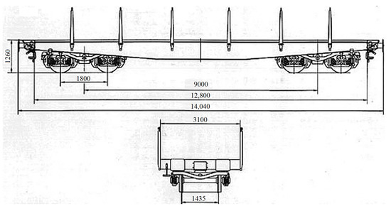
Figure 2.
Cargo bogie Smrs.
The first stage of the methodology covers the formation of a design conceptual project. Taking into account the geometry of the load and the vehicle, constraints are imposed on the design of the structure for maximum filling of the wagon, which allows two positions for loading rollers as each position must be a maximum length of 6 m. For this particular task, a conceptual design for a prismatic structure is formed Figure 3.
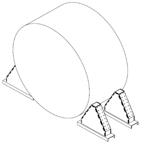
Figure 3.
Conceptual design.
The next stage of the methodology is the determination of the loads acting on the securing structure during transportation. This is a fundamental stage in the design process. Dynamic driving conditions, such as acceleration, braking, and cornering, as well as external factors, such as vibrations from the road surface and weathering, generate forces that can compromise the stability of the cylindrical rollers.
Loads are classified into two types: static and dynamic loads [21].
Static loads include the vertical forces due to the self-weight of the rollers and the gravitational acceleration, g = 9.81 m/s2:
where m is the mass of the pulley and g is the gravitational acceleration.
Dynamic loads arise from changes in vehicle motion and are calculated using dynamic load factors, cx and cz, defined in EN 12195-1:2010 according to EN 15551 and UIC 530 [3,5,6].
Longitudinal forces, along the axis of motion, are calculated using Formula (2):
where the coefficient cx ranges from 0.3 to 0.5, the recommended values according to EN 15551 for railway freight wagons. We assume 0.4.
The transverse forces are the sum of the centrifugal forces acting when moving in a turn and the forces generated by natural phenomena, specifically wind. Centrifugal forces are calculated by Formula (3):
where:
- m—mass of the load;
- —travel speed depends on the standards of the specific country. For Europe, the maximum speed for freight is 120 km/h, regulated in EN 14363. In particular, the standard in Bulgaria limits the speed to 100 km/h, regulated in the Bulgarian Regulation H-7 for railway infrastructure.
- R—radius of the bend. There is no standard norm, but based on the analysis of UIC 606-1 considering the conditions for the minimum radius of the bend, we assume an average value of 500 m.
Wind force is calculated by Formula (4):
where:
- ρ—Air density;
- Vwind—Wind speed;
- Cd—Coefficient of aerodynamic drag;
- A—Design area.
A common transverse force appears to be the equilibrium of the two (5):
Vertical dynamic forces are the forces associated with the vibrations caused by the roughness of the railway infrastructure. These forces can be calculated by Formula (6):
where cz is the value and reaches up to 0.15 when going over bumps.
On the basis of the described steps for the calculation of the loads, the input data and the assumed coefficients and additional parameters are: travel speed 120 km/h, turning radius 500 m, and wind speed 250 km/h [22], the result of which is shown in Table 1.

Table 1.
Results of load calculations.
The third stage of the methodology involves the verification of the conceptual design based on the resulting loads through computer modeling in the Ansys Workbench engineering product environment. A 3D finite element model using solid elements was constructed for the strength analysis. The finite element size was varied, with a maximum size of 60 mm for the general areas of the structure and a minimum size of 5 mm in the areas of contact between the structure and the coils. Standard finite element quality requirements have been met, and solution convergence has been verified. Appropriate boundary conditions have been applied to ensure adequate performance in the service of the structure. Fixed supports were defined in the connection areas with the main bearing system, limiting the displacements in all directions. The loads to which the structure is subjected are presented in Table 1. The following three verification scenarios have been developed (Table 2):
Table 2.
Conditions for the study options.
For each of the scenarios, boundary conditions are set: related to the material characteristic, number of finite elements and nodes between them, and factor of safety. The specific values are given in Table 3.
Table 3.
Boundary conditions.
The results of the simulations performed under the first option are systematized in Table 4 and visualized in Figure 3 and Figure 4.
Table 4.
Option 1 test results.
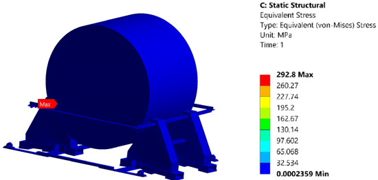
Figure 4.
Finite element analysis of securing structure under vertical static load: von Mises stress distribution.
The results of the simulations performed under the first option are systematized in Table 5 and visualized in Figure 5 and Figure 6.
Table 5.
Option 2 test results.
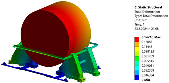
Figure 5.
Finite element analysis of securing structure under vertical static load: total deformation distribution.
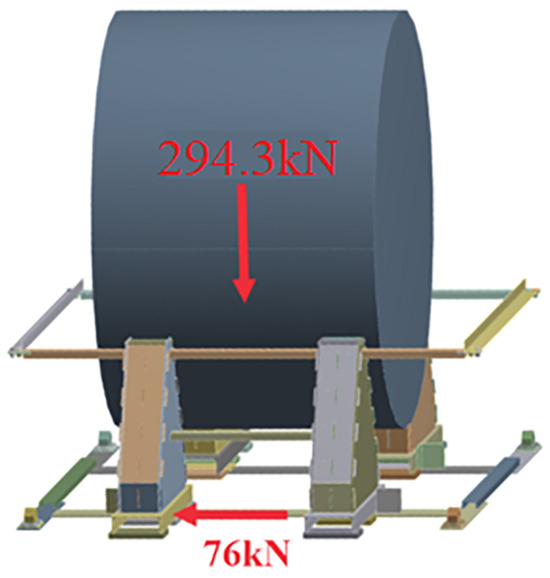
Figure 6.
Loading scheme of the securing structure under vertical and transverse forces.
The results of the simulations performed under the first option are systematized in Table 6 and visualized in Figure 7 and Figure 8.
Table 6.
Option 3 test results.
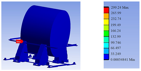
Figure 7.
Finite element analysis of securing structure under combined vertical and transverse loads: von Mises stress distribution.
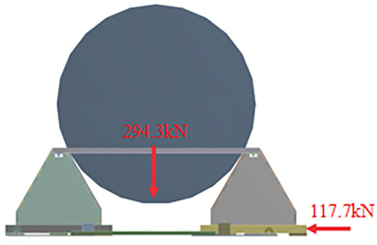
Figure 8.
Loading scheme of the securing structure under vertical and axial forces.
Figure 9 shows the result of a finite element analysis (FEM) of the securing structure for the cylindrical load under combined loads.
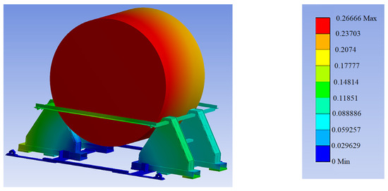
Figure 9.
Finite element analysis of securing structure under combined vertical and transverse loads: total deformation distribution.
The studies carried out show that the proposed structure will withstand the expected load. This stage in the methodology is the final one. In the event that the analysis does not confirm that the structure will carry the load, it is necessary to go back to the conceptual design and change the thicknesses of the structural components.
3. Conclusions
The developed methodology presents a structured approach to the design and verification of securing structures for the transport of cylindrical roller loads by rail. It integrates theoretical postulations, standardized norms, and numerical modeling, thus providing a high degree of reliability in the assessment of structural security.
The analysis of acting loads takes into account both static components resulting from the dead weight of the load and dynamic effects, including longitudinal, transverse, and vertical forces due to accelerations, bends, vibrations, and atmospheric conditions. The assumptions used and the parameters assumed (speed, turning radius, wind force) correspond to real operating conditions according to European and national regulations (EN 14363, Eurocode 1, Regulation H-7, etc.).
Numerical simulations implemented in Ansys Workbench allow detailed verification of the stress state of the structure under different loading scenarios. The results obtained show that in all cases considered, the maximum values of the equivalent (von Mises) stresses remain below the allowable limit for the S355J2 material used, including under combined loads. This confirms that the structure meets the strength and safety criteria without any local or global failure risks.
The design solution is in accordance with the geometrical limitations of the transport rolling stock (freight wagons type Smmps), as well as with the requirements for rational load distribution and maximum filling of the loading area.
The possibility of stable positioning of two roller units within 6 m modules is ensured, minimizing the risk of unwanted shifting or overturning during movement.
The flexibility of the proposed methodology allows its easy adaptation to different types of cylindrical loads with varying dimensions, mass, and transport conditions. At the same time, it can be used as a basis for standardizing engineering practices in the field of transport securing systems, as well as a starting point for developing new designs based on numerical simulations and engineering optimization.
In conclusion, this research contributes to improving the safety and efficiency of specialized cargo transportation by applying an interdisciplinary engineering analysis approach combining classical methods with advanced virtual design and verification tools.
Author Contributions
Conceptualization, P.K. and M.K.; methodology, M.K.; software, P.K.; validation, P.K. and M.K.; formal analysis, P.K.; investigation, P.K. and M.K.; resources, M.K.; data curation, M.K.; writing—original draft preparation, P.K. and M.K.; writing—review and editing, P.K. and M.K.; visualization, P.K.; supervision, P.K. and M.K.; project administration, M.K.; funding acquisition, P.K. All authors have read and agreed to the published version of the manuscript.
Funding
This research was funded by the European Regional Development Fund within the OP “Research, Innovation and Digitalization Programme for Intelligent Transformation 2021–2027”, Project No. BG16RFPR002-1.014-0005, Center of Competence “Smart Mechatronics, Eco- and Energy Saving Systems and Technologies”.
Institutional Review Board Statement
Not applicable.
Informed Consent Statement
Not applicable.
Data Availability Statement
Data will be available on request.
Conflicts of Interest
Marian Kalestrov is a manager of Ka Engineering Ltd. The remaining author declare that the research was conducted in the absence of any commercial or financial relationships that could be construed as a potential conflict of interest.
References
- European Union Agency for Railways. Annual Report on Railway Safety and Interoperability; European Union Agency for Railways: Paris, France, 2023. [Google Scholar]
- Mundrey, J.S. Railway Track Engineering; Tata McGraw-Hill Education Private Limited: New York, NY, USA, 2010; ISBN 1283187825. [Google Scholar]
- EN 12195-1:2010; Load Restraint Assemblies on Road Vehicles—Part 1: Calculation of Securing Forces. European Committee for Standardization (CEN): Brussels, Belgium, 2010.
- ISO 27956:2009; Road Vehicles—Securing of Cargo in Delivery Vehicles—Requirements and Test Methods. ISO: Geneva, Switzerland, 2009.
- EN 15551:2009; Railway Applications—Freight Wagons—Draw Gear and Buffing Gear. CEN: Brussels, Belgium, 2009.
- International Union of Railways (UIC). UIC Code 777-2: Code of Practice for the Loading and Securing of Goods on Railway Wagons; UIC: Paris, France, 2025. [Google Scholar]
- Baranovskyi, D.; Muradian, L.; Bulakh, M. The Method of Assessing Traffic Safety in Railway Transport. IOP Conf. Ser. Earth Environ. Sci. 2021, 666, 042075. [Google Scholar] [CrossRef]
- Iwnicki, S.; Spiryagin, M.; Cole, C.; McSweeney, T. Handbook of Railway Vehicle Dynamics, 2nd ed.; CRC Press: Boca Raton, FL, USA, 2019. [Google Scholar] [CrossRef]
- European Railway Agency. Running Dynamics—Application of EN 14363:2005—Modifications and Clarifications, Technical Document ERA/TD/2012-17/INT, Version 3.0; European Railway Agency: Valenciennes, France, 2014. [Google Scholar]
- Spiryagin, M.; Cole, C.; Sun, Q.; McClanachan, M.; Spiryagin, V.; McSweeney, T. Design and Simulation of Rail Vehicles, 1st ed.; CRC Press: Boca Raton, FL, USA, 2014. [Google Scholar] [CrossRef]
- EN 14363:2016; Railway Applications—Testing for the Acceptance of Running Characteristics of Railway Vehicles—Testing of Running Behaviour and Stationary Tests. CEN: Brussels, Belgium, 2016.
- Ngamkhanong, C.; Ming, Q.; Li, T.; Kaewunruen, S. Dynamic train-track interactions over railway track stiffness transition zones using baseplate fastening systems. Eng. Fail. Anal. 2020, 118, 104866. [Google Scholar] [CrossRef]
- Pilkey, W.D. Peterson’s Stress Concentration Factors; John Wiley & Sons: Hoboken, NJ, USA, 2008. [Google Scholar]
- Hearn, J. Mechanics of Materials 2: The Mechanics of Elastic and Plastic Deformation of Solids and Structural Materials; Butterworth-Heinemann: Oxford, UK, 1997. [Google Scholar] [CrossRef]
- Liu, Z. Finite Element Stress and Failure Analysis of Railway Track Structural System. Doctoral Thesis, Nanyang Technological University, Singapore, 2021. Available online: https://hdl.handle.net/10356/155042 (accessed on 20 June 2025).
- Raychev, R.; Delova, I. Methods for Reducing the Stress Concentration in Cylindrical Specimens at Axial Loading. In Environment. Technology. Resources. Proceedings of the International Scientific and Practical Conference, Rezekne, Latvia, 3 June 2021; Rezekne Academy of Technologies: Rezekne, Latvia, 2021; pp. 300–303. [Google Scholar] [CrossRef]
- Raychev, R.; Delova, I. Reduction of the Stress Concentration Factor of Prismatic Specimens through the Use of Topological Optimization. In Environment. Technology. Resources. Proceedings of the International Scientific and Practical Conference, Rezekne, Latvia, 3 June 2021; Rezekne Academy of Technologies: Rezekne, Latvia, 2021; pp. 296–299. [Google Scholar] [CrossRef]
- Bruni, S.; Vinolas, J.; Berg, M.; Polach, O.; Stichel, S. Modelling of suspension components in a rail vehicle dynamics context. Veh. Syst. Dyn. 2011, 49, 1021–1072. [Google Scholar] [CrossRef]
- Grimaldi, R. Technological Innovations in Rail Freight Transport: An Appraisal Framework and Supporting Tools. Ph.D. Thesis, Sapienza Università di Roma, Roma, Italy, 2016. [Google Scholar] [CrossRef]
- Petrović, D.; Šoškić, Z.; Bogojević, N.; Rakanović, R. Work Regime of DDam Wagon Parabolic Springs. FME Trans. 2005, 33, 129–133. [Google Scholar]
- Petrović, D.; Bižić, M. Experimental Testing of Dynamic Behavior of Railway Vehicles. Mech. Transp. Commun. 2019, 17, 1829. [Google Scholar]
- EN 1991-1-4; Eurocode 1—Actions on Structures—Part 1–4: General Actions—Wind Actions. CEN: Brussels, Belgium, 2005.
Disclaimer/Publisher’s Note: The statements, opinions and data contained in all publications are solely those of the individual author(s) and contributor(s) and not of MDPI and/or the editor(s). MDPI and/or the editor(s) disclaim responsibility for any injury to people or property resulting from any ideas, methods, instructions or products referred to in the content. |
© 2025 by the authors. Licensee MDPI, Basel, Switzerland. This article is an open access article distributed under the terms and conditions of the Creative Commons Attribution (CC BY) license (https://creativecommons.org/licenses/by/4.0/).