Proceeding Paper

Thermal and Structural Analysis of Gasoline Engine Piston at Different Boost Pressures †

by
Krasimir Ambarev
1,2,* and
Stiliyana Taneva
1,2
1
Department of Transport and Aircraft Equipment and Technologies, Faculty of Mechanical Engineering, Technical University of Sofia, Plovdiv Branch, 4000 Plovdiv, Bulgaria
2
Center of Competence “Smart Mechatronics, Eco- and Energy Saving Systems and Technologies”, 4000 Plovdiv, Bulgaria
*
Author to whom correspondence should be addressed.
Presented at the 14th International Scientific Conference TechSys 2025—Engineering, Technology and Systems, Plovdiv, Bulgaria, 15–17 May 2025.
Eng. Proc. 2025, 100(1), 38; https://doi.org/10.3390/engproc2025100038
Published: 14 July 2025

Abstract

The piston, as one of the main components of the crankshaft mechanism, is subjected to significant mechanical and thermal loads. The mechanical properties of the alloy from which it is made and the technology of its manufacture are related to the maximum allowable value of the combustion pressure. The purpose of this paper is to determine the maximum value of the boost pressure of an existing gasoline engine, without causing damage to its piston. To achieve this goal, the stress and strain state of the piston was determined using finite element analysis (FEA) with consideration of the influence of temperature at different values of the boost (intake) pressure. The temperature distribution of the piston was determined using transient thermal analysis. The analyses were performed using SolidWorks Simulation. The obtained results were compared and analyzed.

1. Introduction

An internal combustion engine (ICE) is a heat machine that converts the thermal energy released during fuel oxidation into useful mechanical work at the output of the crankshaft. The piston, as an element of the crankshaft-connecting rod-piston system, is subjected to thermal and mechanical load. One of the options for increasing the power of an ICE is through boost pressures with a turbocharger or a mechanical compressor. The maximum value of the boost pressure is determined by the permissible piston load.
Currently, the challenge of ensuring high quality and reducing the time required for design and engineering tasks is particularly relevant, and in the last decade researchers have increasingly used the finite element method (FEM) in their developments in the design, research, and analysis of systems, components, and assemblies, both of the internal combustion engine [1,2,3,4] and the vehicle [5,6,7].
Various authors have investigated the temperature and stress distribution of pistons using the FEA method with various software products [1,2,3,4,8,9,10,11,12,13,14,15]. In [1,3], the authors used FEA to optimize some of the dimensions and shapes of different pistons.
In some of the publications [8,9,10], the influence of the coating on the temperature of the piston is also considered, and in [16], the effect of anti-scuffing coating on the temperature gradient of aluminum pistons with anodized coating was determined through an experimental test.
Piston thermal stresses must be kept below levels that would cause failure and gasoline engine piston temperatures should be around 300 °C for aluminum alloys [17,18].
In most of these works, the authors used steady-state thermal analysis, and when conducting the structural analysis, the piston is fixed, which does not actually take into account the correct type of fixation of the piston during its operation.
The aim of this work is to determine the maximum value of the boost pressure of a gasoline internal combustion engine by conducting transient thermal analysis and static strength analysis to determine the stress–strain state of the piston using FEA. The computer simulations were conducted for the most loaded operating modes of the engine during the combustion process.

2. Materials and Methods

The computer simulations performed include transient thermal analysis and static strength analysis, taking into account the influence of temperature. FEA was employed using the Simulation module of SolidWorks 2023 software. The analyses were performed for a piston of a real four-stroke, four-cylinder internal combustion engine with water cooling, a gasoline injection system, compression ratio ε = 11, and nominal power Ne = 60 kW at engine speed n = 5800 min−1. Initially, a thermal calculation for the engine was performed without boost pressure. The maximum value of the working pressure during the combustion process, pzmax = 5.7 MPa, and the actual value of the mean effective pressure, p = 1.095 MPa, were calculated. The obtained values for the piston stroke and cylinder diameter from the thermal calculation when operating a naturally aspirated ICE are, respectively, S = 76.5 mm and D = 72 mm, and correspond to the values of the real engine. A thermal calculation was subsequently performed on the same engine at two different boost pressures.
In order to correspond to the real operating conditions of the piston and to apply the corresponding fixations and loads, three-dimensional geometric models of the piston, piston pin, cylinder, connecting rod bearing, and part of the connecting rod were created. Figure 1 illustrates a three-dimensional geometric model of the simulation study object “piston”.
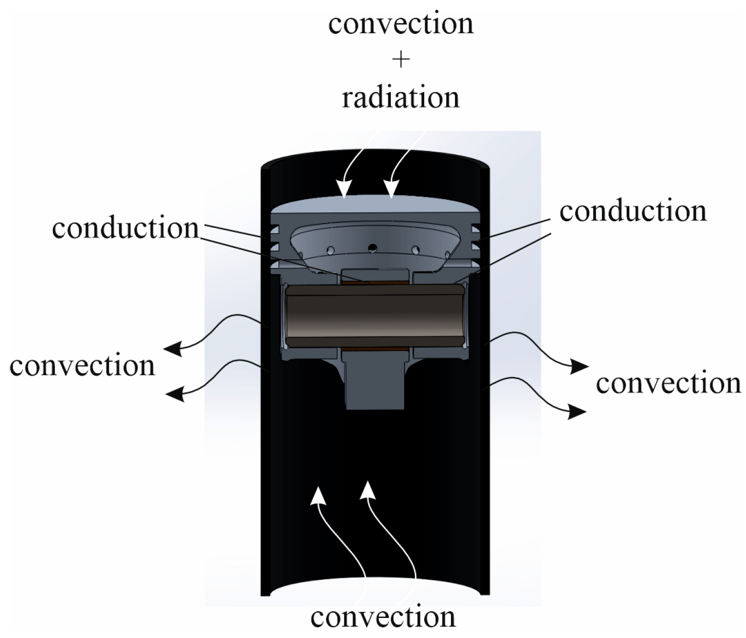
Thermal analysis is related to the mechanism of heat transfer, which affects engine performance, emissions, and efficiency. Figure 2 presents the heat transfer mechanism in ICE.
Convection heat transfer, also known as Newton’s law, can be determined by the relationship [19,20]
Q1 = hA1(TS − TF),
where Q1 is the heat transferred by convection [W]; ℎ is the convection heat transferred coefficient, and depends on the type of fluid and its velocity [W/m2.K]; A1 is the surface area of the solid body [m2]; TS is the solid surface temperature [K]; and TF is the fluid temperature [K].
Conductive heat transfer depends somewhat on the temperature of the material, and can be determined Fourier’s equation [19,20]
Q = kA(TH − TC)/L,
where Q is the heat transferred by conduction [W]; k is the thermal conductivity [W/m.K]; A is the cross-section area of the heat transfer [m2]; TH is the temperature on the hot side [K]; TC is the temperature on the cold side [K]; and L is the distance of heat travel.
The radiation heat transfer includes gas radiation (CO2, H2O and CO) and soot particle radiation. The radiation heat transfer can be determined by the relationship [20]
q = εσ(TS)4
where q is heat flux (heat emitted by radiation per unit of area) [W/m2]; ε is a radiative property of a surface called emissivity and depends strongly on the surface material and finish; σ is the Stefan–Boltzmann constant, which equals 5.67 × 10⁻⁸ W/m2K4; and TS is the solid surface temperature [K].

2.1. Thermal Boundary Conditions

The piston thermal boundary conditions can basically be divided into two groups.
The convection heat transfer coefficient of the gas can be determined by the empirical relationships developed by Hohenberg, Woschni, and Annand [21] using easily measured or derived engine parameters.
In thermal analysis, the empirical equation devised by Hohenberg was used to determine the convection heat transfer coefficient of the gas during the combustion process [8,21].
hgas = αV(t)−0.06p(t)0.8T(t)−0.4(vp + b)0.8
where V(t) is the instantaneous cylinder volume, m3; p(t) is the instantaneous cylinder pressure, bar; T(t) is the instantaneous temperature, K; α and b are the calibration constants, respectively, 130 and 1.4 [8]; and vp is the average piston speed, m/s.
The change in the convective heat transfer coefficient of the gas and temperature along the piston crown and in the upper part of the cylinder are set by a curve as a function of the time required for ignition. An initial temperature is also set.
The thermal boundary conditions of the second group consist of the boundary conditions of the piston ring land and the piston underside, and the convective heat transfer coefficients are determined, making some assumptions, and are defined as in [9,12,17,22]. The value of the heat transfer coefficient for the rings is calculated in [22]. The convective heat transfer between the piston crown and the cylinder is neglected, due to a small gap [9,12]. The oil temperature is T = 110 °C, and the coolant temperature is T = 95 °C. The value of resistance between the cylinder and the piston is calculated in [22]. The necessary connections between the piston and the piston pin, the piston pin and the connecting rod bearing, and the connecting rod bearing and the relevant part of the connecting rod are specified. Gasoline engines are considered to be less influenced by radiative heat transfer [13,14]; therefore, radiation heat transfer is neglected.

2.2. Static Boundary Conditions

The connections are defined, describing the interaction between the individual parts that are in contact with each other. To realize the real operating conditions of the piston, the fixations to the model are as follows: on the lower surface of the cylinder and on its upper part, and using a slider on the flat surface of the connecting rod.
The load on the piston crown and in the upper part of the cylinder is realized by setting the maximum value of the pressure during combustion.

2.3. Material Properties

Aluminum-silicon eutectic alloys (silumins) are used to make pistons. Table 1 presents the mechanical properties of the selected materials for the piston and the other parts. The piston is made of aluminum alloy 2618-T16 (SS), a cylinder of ductile iron (SN), a piston pin of 4340 steel, annealed, a piston pin bearing of aluminum bronze, and a connecting rod of aluminum alloy 7075-T6 (SN).

3. Results and Discussion

3.1. Results of Thermal Calculation at ICE

Three engine operation options were selected, for each of which thermal calculations were performed. Case I (base variant)—the engine is without boost pressure, nominal power Ne = 60 kW at engine speed n = 5800 min−1, and compression ratio ε = 11. Case II—engine operation with boost pressure pk = 0.125 MPa and compression ratio ε = 8. The nominal power obtained in this case is Ne = 68 kW at engine speed n = 5800 min−1. Case III—engine operation with boost pressure—pk = 0.12 MPa, and compression ratio—ε = 11. The nominal power obtained in this case is Ne = 74 kW at engine speed n = 5800 min−1.
All three options are for the same value of the stroke and the diameter of the piston, corresponding to an actual engine. After the thermal calculations, the values of various parameters were determined for the three cases, some of which are input for conducting computer simulations.

3.2. FEA Results

The same mesh was used in both analyses. A three-dimensional blended curvature-based mesh with a maximum element size of 9 mm, a minimum element size of 0.45 mm, and high mesh quality was generated, and for some surfaces, a mesh control was used. Figure 3 presents the 3D mesh.

3.2.1. Transient Thermal Analysis Results

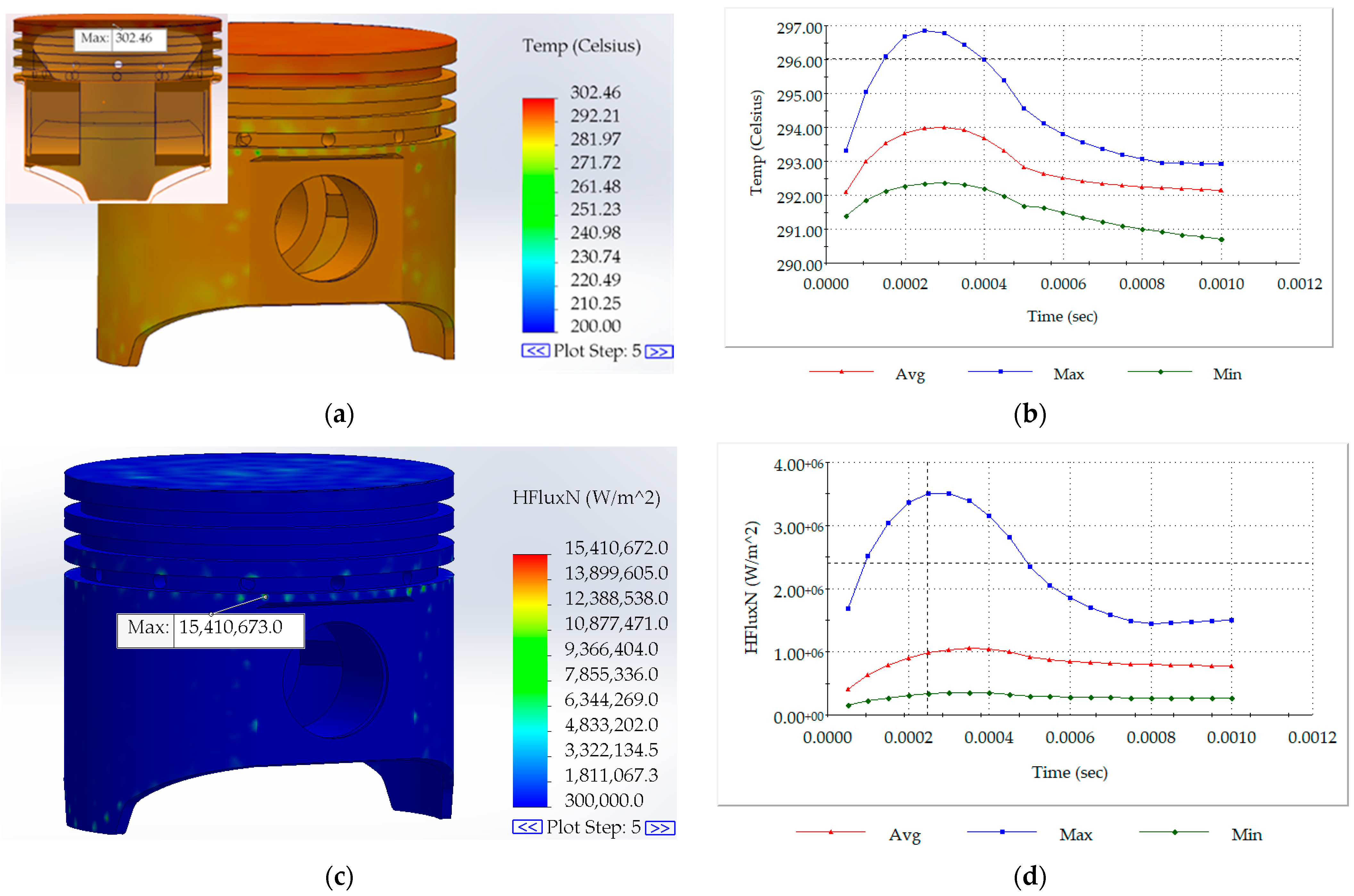
The following figures show some of the obtained results of the analysis in the different cases, which include the temperature distribution of the piston, the temperature distribution of the piston crown, and heat flux.
Figure 4a presents the results for the temperature distribution of the piston, Figure 4b presents the graphical results for the minimum, maximum, and average temperature distribution on the piston crown surface at different points, Figure 4c presents the results of piston heat flux, and Figure 4d present the graphical results for the minimum, maximum, and average heat flux on the piston crown surface at different points in Case I.
Figure 5a–d and Figure 6a–d present the results for the temperature distribution of the piston in Case II and Case III, respectively.
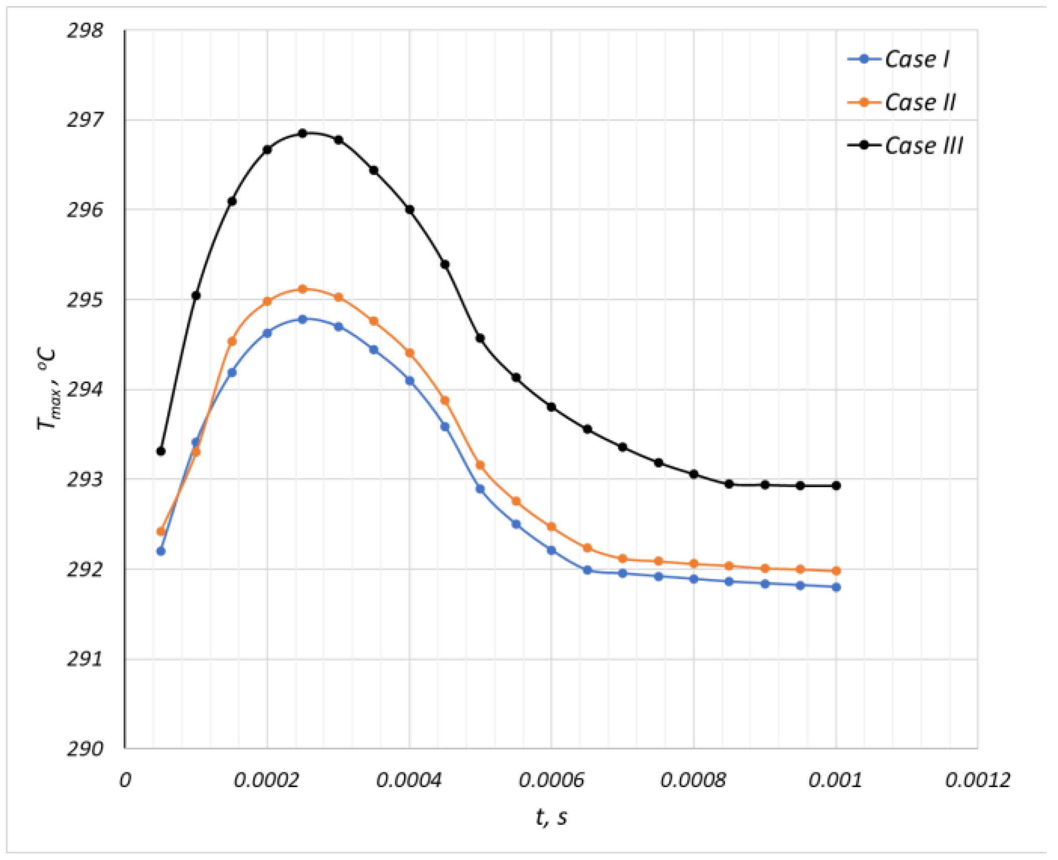
Figure 7 presents the graphical results for the maximum value of temperature distribution in time on the piston crown surface of the considered cases.
Among the presented variants of transient thermal analysis, the highest values of the obtained maximum temperature are observed in Case III, with a maximum value of around 297 °C.

3.2.2. Structural Analysis Results

Structural analysis includes static strength analysis with consideration of the influence of temperature in the same cases as the thermal analysis.
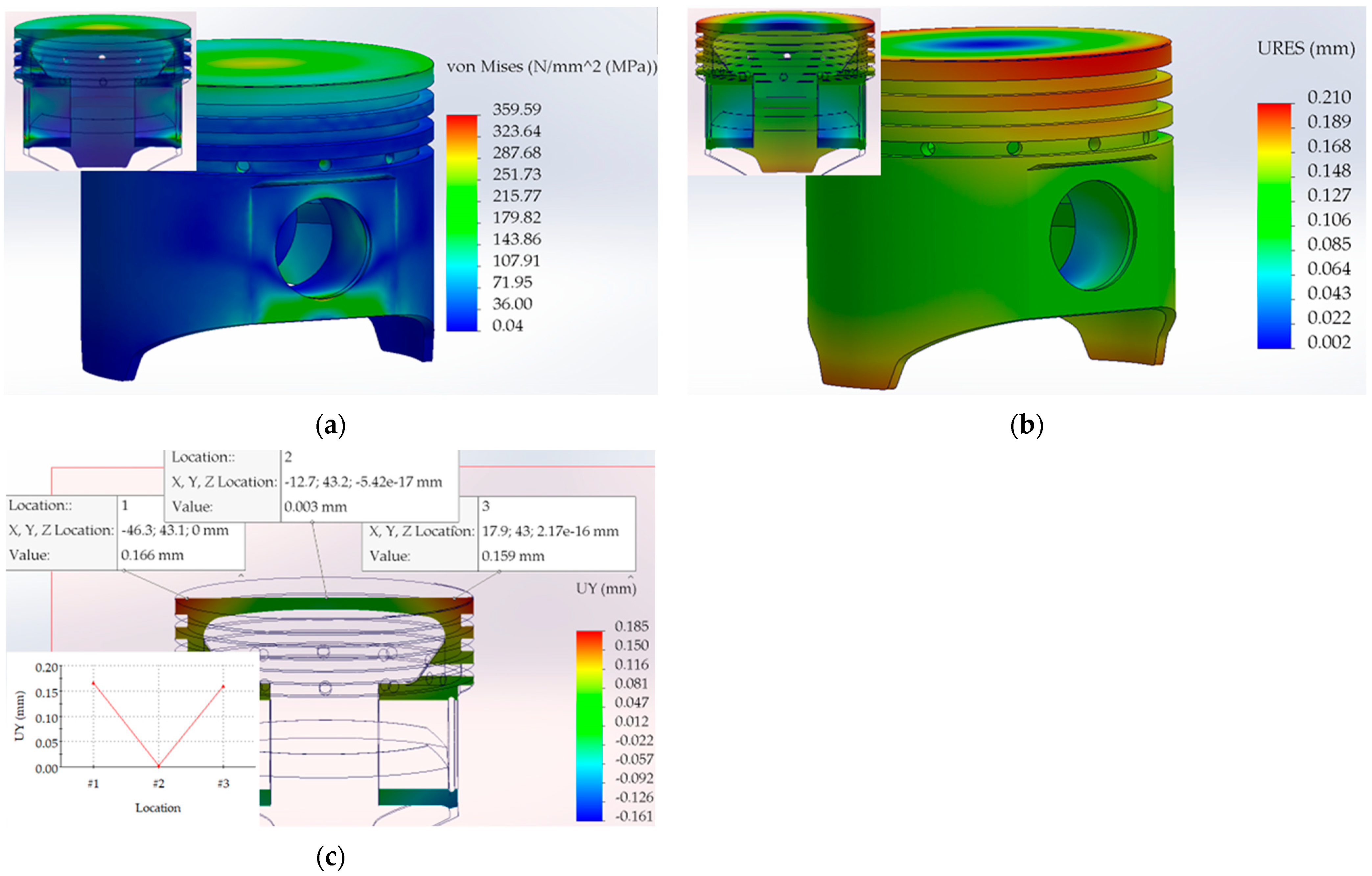
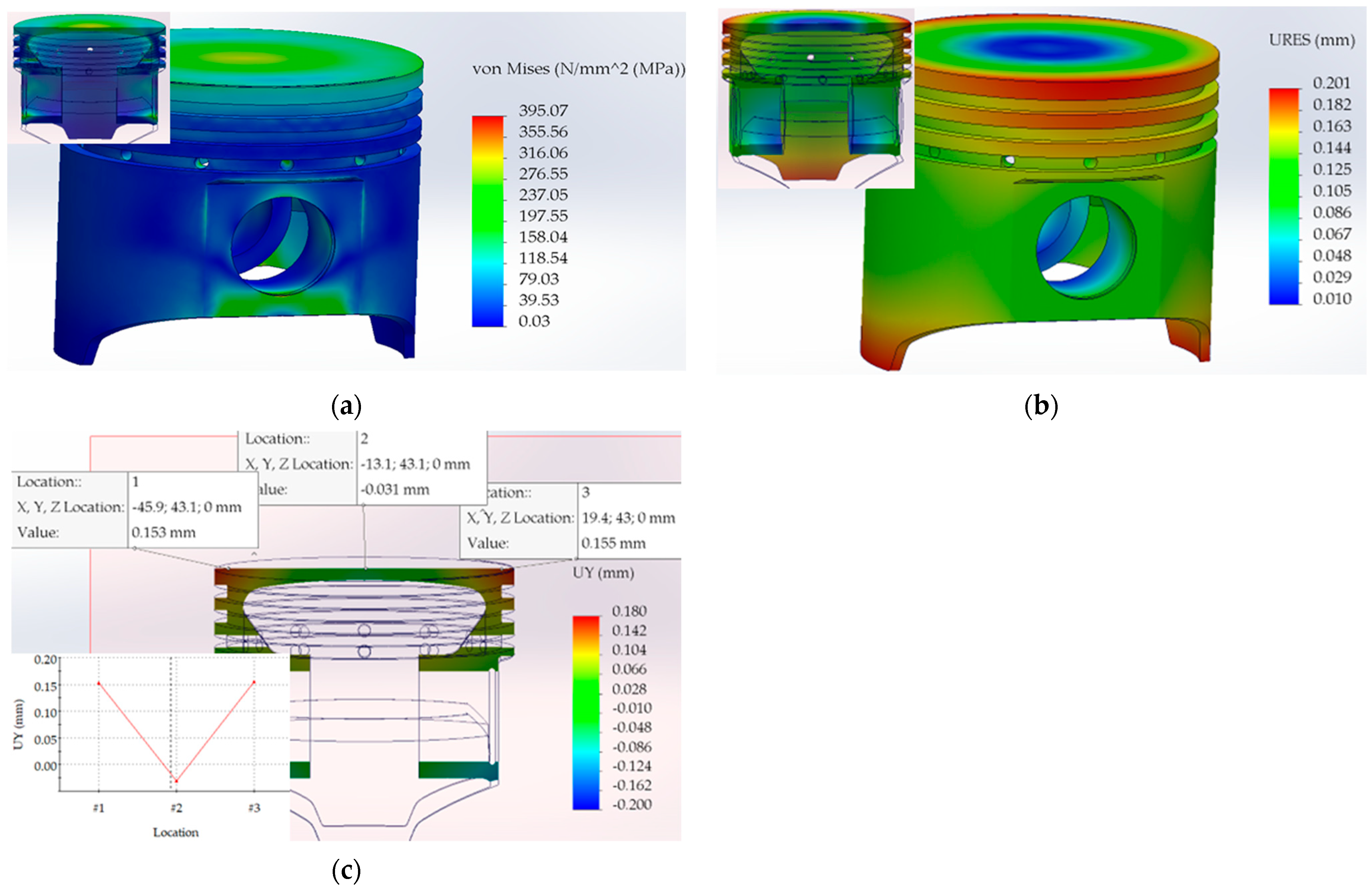
The following figures show some of the obtained results of the numerical study, which include the equivalent stress, the absolute displacement of the piston, and displacement along Y in different points of the top surface of the sectional piston. Figure 8, Figure 9 and Figure 10 present the static results of the piston in Case I, Case II, and Case III, respectively.
The results of the structural analysis for the three cases regarding the maximum equivalent piston stress show that the highest value is around 540 MPa. This value is higher than the yield strength of the material and was obtained in Case III.
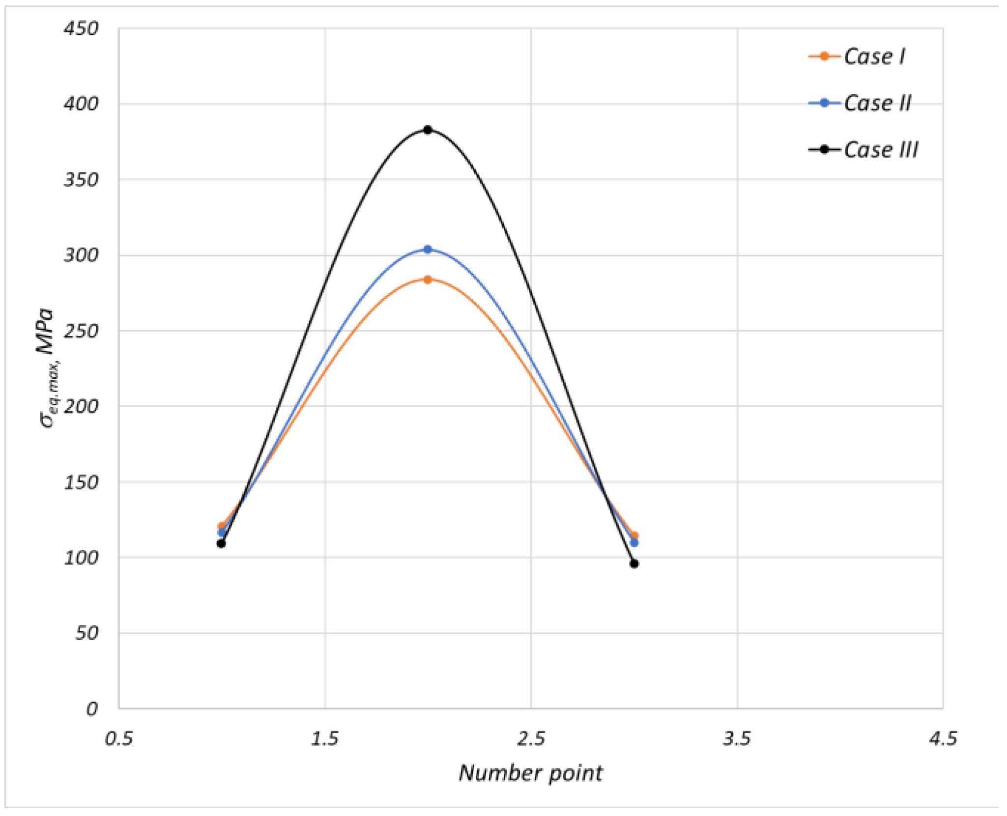
Figure 11 presents the graphical results for the maximum value of the equivalent stress at three points at the same location on the piston crown surface of the considered cases. One of the points is located in the middle of the piston crown surface.
Figure 11 shows that the maximum equivalent piston stress at the middle of the crown is around 382 MPa for Case III, and this value is higher than the yield strength of the material, which is 372 MPa.

4. Conclusions

Based on the performed analyses, the following conclusions are made.
In the third variant of engine operation (Case III), the piston will be damaged, because the obtained results for the maximum equivalent stress are higher than the yield strength of the material. Therefore, when operating an internal combustion engine with a boost pressure pk = 0.125 MPa, and a lower compression ratio ε = 8 (Case II), the results obtained for the piston stresses are within the yield strength of the material, and there is no danger of piston damage.
The maximum safe boost pressure and maximum (nominal) power of engines with the original engine pistons can be pre-determined by conducting simulation studies using FEM.
The thermal analysis performed and the results obtained can be verified with an experimental test, and then can be used to refine the methodology.

Author Contributions

Conceptualization, K.A. and S.T.; methodology, K.A. and S.T.; software, S.T.; resources, K.A.; writing—original draft preparation, K.A. and S.T.; writing—review and editing, S.T.; visualization, S.T.; supervision, K.A.; project administration, K.A.; funding acquisition, K.A. All authors have read and agreed to the published version of the manuscript.

Funding

This research was funded by the European Regional Development Fund within the OP “Research, Innovation and Digitalization Programme for Intelligent Transformation 2021-2027”, Project CoC “Smart Mechatronics, Eco- and Energy Saving Systems and Technologies”, No. BG16RFPR002-1.014-0005.

Institutional Review Board Statement

Not applicable.

Informed Consent Statement

Not applicable.

Data Availability Statement

Data are contained within the paper.

Conflicts of Interest

The authors declare no conflicts of interest.

References

  1. Singh, A.R.; Sharma, P.K. Design, Analysis and Optimization of Three Aluminium Piston Alloys Using FEA. Int. J. Eng. Res. Appl. 2014, 4, 94–102. [Google Scholar]
  2. Kumar, A.; Gangrade, K. Design Thermal and Structural Analysis of Piston with Different Materials Using Finite Element Analysis. Int. J. Res. Publ. Rev. 2022, 3, 3814–3819. [Google Scholar]
  3. Zhaoju, Q.; Yingsong, L.; Zhenzhong, Y.; Junfa, D.; Lijun, W. Diesel engine piston thermo-mechanical coupling simulation and multidisciplinary design optimization. Case Stud. Therm. Eng. 2019, 15, 100527. [Google Scholar] [CrossRef]
  4. Dagar, N.; Sharma, R.; Rinawa, M.L.; Gupta, S.; Chaudhary, V.; Gupta, P. Design and analysis of piston using aluminum alloy and composites in SolidWorks and Ansys. Mater. Today Proc. 2022, 67, 784–791. [Google Scholar] [CrossRef]
  5. Valkov, G.; Nikolov, V. Analysis of stresses and deformations in the chassis of terrain forklifts. IOP Conf. Ser. Mater. Sci. Eng. 2020, 878, 012038. [Google Scholar] [CrossRef]
  6. Ijagbemi, C.O.; Oladapo, B.I.; Campbell, H.M.; Ijagbemi, C.O. Design and simulation of fatigue analysis for a vehicle suspension system (VSS) and its effect on global warming. Procedia Eng. 2016, 159, 124–132. [Google Scholar] [CrossRef]
  7. Georgiev, Z.; Kunchev, L. Study of the stresses in the front suspension components of a car passing over speed breakers. IOP Conf. Ser. Mater. Sci. Eng. 2019, 664, 012012. [Google Scholar] [CrossRef]
  8. Cerit, M.; Coban, M. Temperature and thermal stress analyses of a ceramic-coated aluminum alloy piston used in a diesel engine. Int. J. Therm. Sci. 2014, 77, 11–18. [Google Scholar] [CrossRef]
  9. Buyukkaya, E. Thermal analysis of functionally graded coating AlSi alloy and steel pistons. Surf. Coat. Technol. J. 2008, 202, 3856–3865. [Google Scholar] [CrossRef]
  10. Ahmed, A.; Wahab, M.S.; Raus, A.A.; Kamarudin, K.; Bakhsh, Q.; Ali, D. Thermal Effect on the Automobile Piston: A Review. Indian J. Sci. Technol. 2016, 9. [Google Scholar] [CrossRef]
  11. Muhammad, A.; Haruna, S.I. Finite element analysis of the heat transfer in a piston. J. Mod. Manuf. Syst. Technol. 2020, 4, 45–51. Available online: https://www.researchgate.net/publication/340244705 (accessed on 28 April 2025). [CrossRef]
  12. Esfahanian, V.; Javaheri, A.; Ghaffarpour, M. Thermal analysis of an SI engine piston using different combustion boundary condition treatments. Appl. Ther. Eng. J. 2006, 26, 277–287. [Google Scholar] [CrossRef]
  13. Borman, G.; Nishiwaki, K. Internal-combustion engine heat transfer. Prog. Energy Combust. Sci. J. 1987, 13, 1–46. [Google Scholar] [CrossRef]
  14. Yue, Z.; Reitz, R. Numerical investigation of radiative heat transfer in internal combustion engines. Appl. Energy J. 2019, 235, 147–163. [Google Scholar] [CrossRef]
  15. Subbaraoa, R.; Gupta, S. Thermal and structural analyses of an internal combustion engine piston with suitable different super alloys. Mater. Today Proc. 2020, 22, 2950–2956. [Google Scholar] [CrossRef]
  16. Kadikyanov, G. Research temperature gradient of aluminum piston with coatings. In Proceedings of the Trans&MOTAUTO’09, Sunny Beach, Bulgaria, 17–19 September 2009; pp. 95–97, ISBN 1313-5031. [Google Scholar]
  17. Bojadjiev, K.; Traikov, L. Construction, Design and Calculation of ICE.; Technica: Sofia, Bulgaria, 1990. [Google Scholar]
  18. Heywood, J. Internal Combustion Engine Fundamentals; McGraw-Hill Bock Company: Singapore, 1998. [Google Scholar]
  19. Available online: https://www.simscale.com/docs/tutorials/heat-transfer-engine-piston/ (accessed on 28 April 2025).
  20. Available online: https://help.solidworks.com/2023/english/solidworks/cworks/c_Mechanisms_of_Heat_Transfer.htm (accessed on 28 April 2025).
  21. Soyhan, H.S.; Yasar, H.; Walmsley, H.; Head, B.; Kalghatgi, G.T.; Sorusbay, C. Evaluation of heat transfer correlations for HCCI engine modelling. Appl. Therm. Eng. 2008, 29, 541. Available online: https://hal.science/hal-00498971 (accessed on 28 April 2025). [CrossRef]
  22. Taneva, S.; Ambarev, K. Thermal analysis of a piston from an internal combustion gasoline engine. J. BulCToMM Mech. Mach. 2025, 133, 85–92. [Google Scholar]
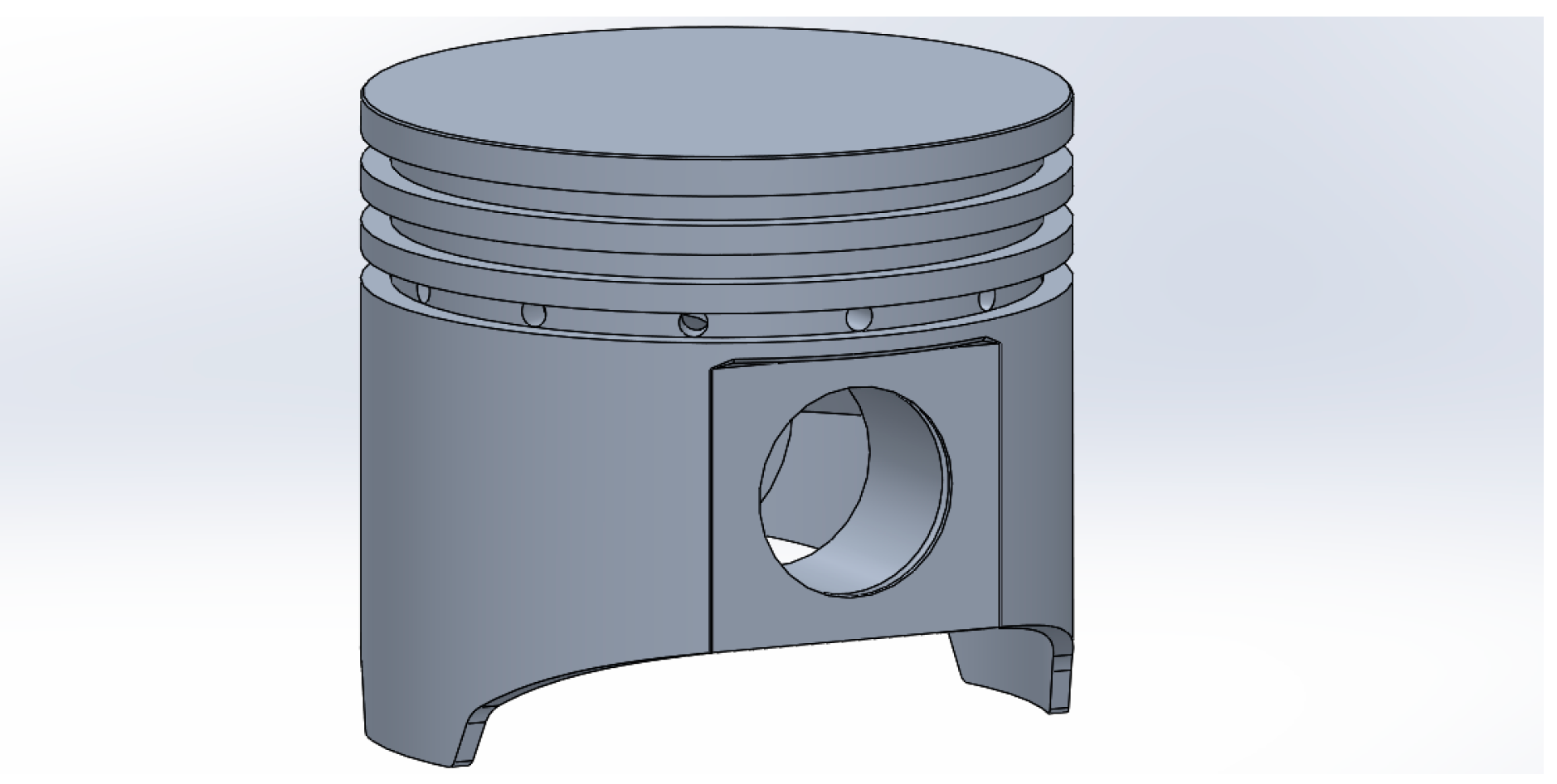
Figure 1. Three-dimensional model of the piston.
Engproc 100 00038 g001
Figure 2. Heat transfer mechanism.
Engproc 100 00038 g002
Figure 3. Mesh.
Figure 3. Mesh.
Engproc 100 00038 g003
Figure 4. Temperature and heat flux—Case I: (a) piston temperature; (b) piston crown surface temperature; (c) piston heat flux; (d) piston crown surface heat flux.
Engproc 100 00038 g004aEngproc 100 00038 g004b
Figure 5. Temperature and heat flux—Case II: (a) piston temperature; (b) piston crown surface temperature; (c) piston heat flux; (d) piston crown surface heat flux.
Engproc 100 00038 g005
Figure 6. Temperature and heat flux—Case III: (a) piston temperature; (b) piston crown surface temperature; (c) piston heat flux; (d) piston crown surface heat flux.
Engproc 100 00038 g006
Figure 7. Maximum temperature distribution in time of the piston crown.
Engproc 100 00038 g007
Figure 8. Stress and displacement—Case I: (a) equivalent stress; (b) absolute displacement; (c) displacement in Y.
Engproc 100 00038 g008
Figure 9. Stress and displacement—Case II: (a) equivalent stress; (b) absolute displacement; (c) displacement in Y.
Engproc 100 00038 g009
Figure 10. Stress and displacement—Case III: (a) equivalent stress; (b) absolute displacement; (c) displacement in Y.
Engproc 100 00038 g010
Figure 11. Maximum equivalent stress on the piston crown surface.
Engproc 100 00038 g011
Table 1. Material properties.
PropertiesPistonCylinderPiston PinPiston Pin BearingConnecting Rod
Density (kg/m3)27607100785074002810
Thermal
conductivity (W/(m.K))
1467544,556130
Expansion coefficient (/K)2.2 × 10−51.1 × 10−51.23 × 10−51.7 × 10−52.36 × 10⁻⁵
Elastic modulus (N/mm2)74,500120,000205,000110,00072,000
Specific heat (J/(kg.K))875450475380960
Poisson’s ratio0.330.310.2850.30.33
Disclaimer/Publisher’s Note: The statements, opinions and data contained in all publications are solely those of the individual author(s) and contributor(s) and not of MDPI and/or the editor(s). MDPI and/or the editor(s) disclaim responsibility for any injury to people or property resulting from any ideas, methods, instructions or products referred to in the content.