1. Introduction
Hoisting mechanisms are parts of lifting and material handling machines. Their elements experience significant dynamic loads during operation, particularly during transient modes. These loads are generated by the operation of the drive motor and the elasticity of components such as shafts, couplings, ropes, and clearances in the kinematic chain. Although the dominant load in hoisting mechanisms is static and is caused by the weight of the load, the uneven movement of heavy masses, combined with elastic elements, turns dynamic impacts into a determining factor for the system’s reliability. Dynamic processes are analyzed by many classic studies using analytical, numerical, and experimental methods [
1,
2,
3,
4,
5,
6].
Modern researchers continue to pay attention to the dynamic modeling of hoisting mechanisms. The monograph [
7] focuses on multiparameter studies of crane dynamics, developing and validating precise mathematical models of overhead cranes, and determining their dynamic characteristics. The authors of [
8] use models with three degrees of freedom to find an optimal law of motion which reduces dynamic loads through smooth motor speed control. A similar method is also applied in [
9], where the motion of a model with three degrees of freedom is studied under a sinusoidal law. A detailed dynamic model of a container crane is created in [
10] that considers the gearbox, boom, and rope’s elasticity, and highlights the substantial impact of trapezoidal motion laws on vibrations. A multi-body dynamic model is used in [
11] to study the dynamic behavior of a polar crane’s hoisting mechanism under emergency conditions. In emergency stopping by a mechanical brake, in [
12], a mathematical model developed using Hamilton’s principle was investigated, and facts useful for design and exploitation practice were established.
The ropes, which are among the most heavily loaded elements of the hoisting mechanisms, require special attention. Acceleration, sudden stops, impacts, vibrations, and load swinging cause them to take on additional loads. Technical and design parameters determine the applied laws of acceleration and speed, which ultimately affect the loads in the ropes. To ensure the safety and reliability of hoisting mechanisms, it is important to study the dynamic factor in the rope. The dynamic factor is the ratio of the rope’s force during the mechanism’s operation to its static force. According to the European standard [
13], the dynamic factor should be determined based on the elasticity class of the crane’s metal structure and the speed of hoisting the load. The paper [
14] and the extensive monograph [
15] compare two models of the steel rope when driving the mechanism by an asynchronous motor with a wound rotor. The findings suggest that the Bouc-Wen hysteresis model offers a precise estimation of the maximum dynamic factor. However, determining the numerical values of the nine constants requires specialized methods [
16,
17]. An essential aspect of these studies is that a dynamic model of an asynchronous motor was used, allowing for more accurate transient modeling. In paper [
18], the dynamics of a bridge crane with a truss metal structure, an asynchronous motor, and a two-stage planetary gear are studied, and a dynamic factor of about 1.93 is obtained. Another interesting study is [
19], which considers vibrations caused by dynamic loading during load hoisting with a bridge crane. The finite element method and discrete mass models (2 and 4 degrees of freedom) were compared, and it was determined that the 4-degree-of-freedom model provides more accurate results. The dynamic factor of 107 cranes is analyzed using a phenomenological model with 4 degrees of freedom, and the results are presented in [
20]. The authors concluded that the results for the dynamic factor are not more than 20% different from the normative values listed in [
13]. A mathematical model of a boom crane has been proposed by the authors of [
21], and simulations have revealed severe dynamic overloads when hoisting loads. This study suggests that the use of only design measures to limit dynamic phenomena does not always yield sufficiently effective results. Active motor control through a feedback system implementing smooth motion laws is a practical method for reducing the dynamic factor of the rope. By using this approach, dynamic overloads are reduced from over 25% to about 5% in [
22].
Despite the many studies available, these aspects can be noted, which have not been given enough attention: (1) The models do not consider the influence of the characteristics of the drive motor on the dynamic characteristics of the mechanism; (2) The influence of various system parameters on the maximum value of the dynamic factor is not thoroughly investigated. This paper aims to develop a mathematical model of the hoisting mechanism for estimating the maximum dynamic factor in the rope, which considers the inertial, damping, and elastic characteristics of the mechanical system, as well as the specific parameters of the driving DC motor. Through an extensive numerical parametric study, the key design and technical factors with the most decisive influence on the dynamic factor in the rope will be identified, which will improve the design and operational characteristics of the hoisting equipment.
3. Results
Several numerical experiments were carried out to analyze the system’s dynamic behavior and identify the highest values of the dynamic factor in the rope. By integrating the following system of differential equations, the numerical characteristics of the system were obtained:
In (6), the DC motor’s rheostatic starting is simulated using coefficients
ai and
bi for the starting stages, as shown in
Table 1.
The motor torque increases from 126.5 to 150 Nm during start-up.
Two typical scenarios of hoisting a payload have been studied numerically. The first scenario involves hoisting a hanging payload “from the air” by using a rope that is initially tight. During the entire period of movement, the payload’s mass remains constant at
m2. The second scenario involves lifting the payload with ropes that are initially slack and a payload on the ground. The hoisting of the payload starts when all the slack in the rope has been eliminated, and at this moment, the motor has already reached the steady state. Here, the mass
m2 is modeled by the following function:
This function simulates starting the motor with slack ropes (at a small value of ) and changing the mass to the nominal value after a period t*, which is enough to take up the slack.
The rope is a complex element with nonlinear characteristics and complex physical behavior [
26], but for small deformations and a linear model, it can be assumed that its stiffness coefficient
c5 and damping coefficient
b5 are determined by the following relationships [
14,
15,
27]:
where
n is the number of ropes on which the payload hangs,
Er is the elasticity modulus of the rope,
S is the cross-section of the rope,
L0 is the initial length of the rope,
is a dimensionless damping coefficient for steel ropes,
mr is the mass of the rope, and
is the density of the steel.
The force in the rope
Fr is calculated from the following:
In the simulation model, through additional mathematical equations, it is considered that the rope works only in tension.
The dynamic factor in the rope
Kd is defined as the ratio of the force in the rope (12) and the static force in the rope caused by the weight of the payload:
The following nominal parameter values were used in the simulation: m1 = 5 × 10³ kg, , , t* = 1.2 s, J1 = 0.205 kgm2, J2 = J4 = 1.22 × 10⁻³ kgm2, J3 = J5 = 1.125 × 10⁻¹ kgm2, J6 = 10.2 kgm2, c1 = 12.5 × 10³ Nm/rad, c2 = 123 × 103 Nm/rad, c3 = 508 × 103 Nm/rad, c4 = 4.8 × 10⁶ N/m, R = 0.25 m, g = 9.81 m/s2, i1 = 9.1, i2 = 9.2, i3 = 2, b1 = 1.25 × 10³ Nms, b2 = 2.5 × 10³ Nms, b3 = 2.5 × 10³ Nms, b4 = 2.5 × 10³ Ns/m, ξ = 0.07, Er = 1.1 × 10¹¹ Pa, b6 = b7 = 1 Nms, L0 = 10 m, n = 4, ρ = 7.85 × 10³ kg/m3, TE = 0.02 s, and S = 1 × 10⁻⁴ m2.
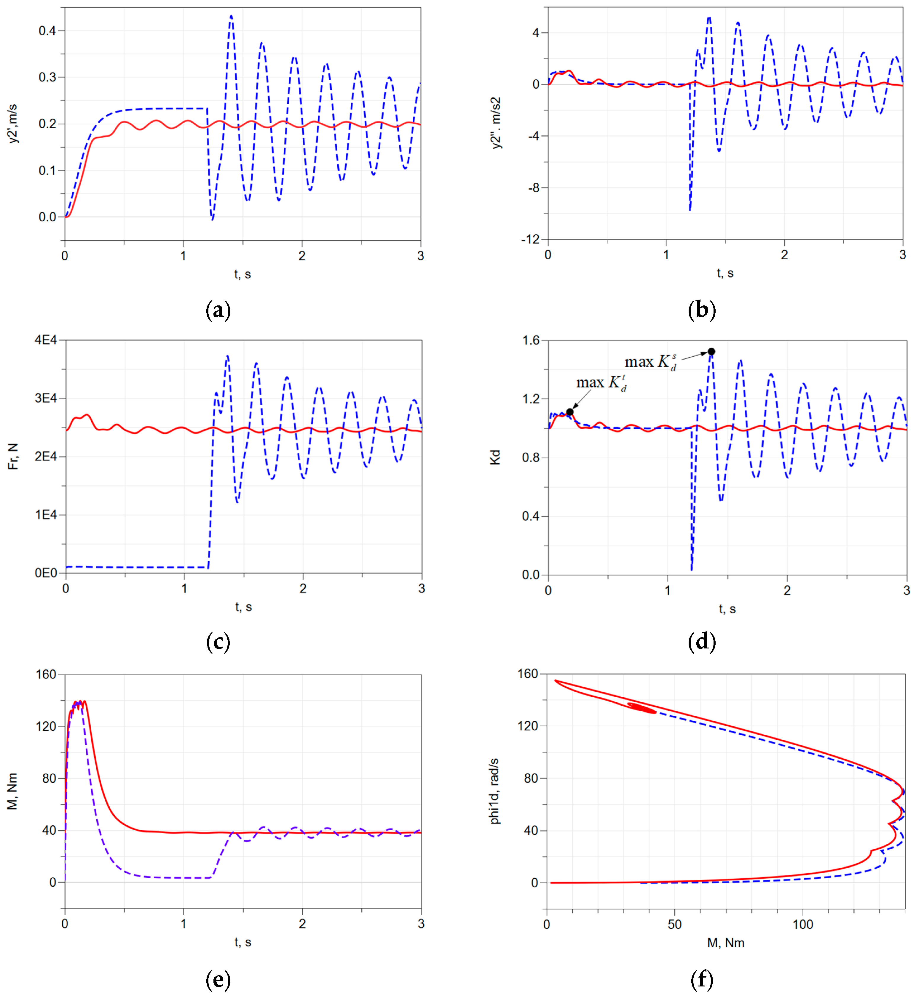
Figure 2 reveals some kinematic and force characteristics of the system through numerical analysis of differential equation (7) using nominal parameters.
A continuous red line is used to represent the characteristics of the tight rope scenario, while a dashed blue line is used to represent the characteristics of the slack rope scenario. The following characteristics are displayed: (1)
Figure 2a—the linear velocities of the payload
; (2)
Figure 2b—the accelerations of the payload
; (3)
Figure 2c—the force in the rope
Fr; (4)
Figure 2d—the dynamic factors for both scenarios, where
denotes the maximum value of the dynamic factor for the slack rope scenario, and
is used for the tight rope scenario; (5)
Figure 2e—the DC motor torque; (6)
Figure 2f—the torque-speed characteristic of the motor
. The characteristics of the slack rope scenario vary greatly, and the maximum dynamic factor is significantly greater than in the tight rope scenario.
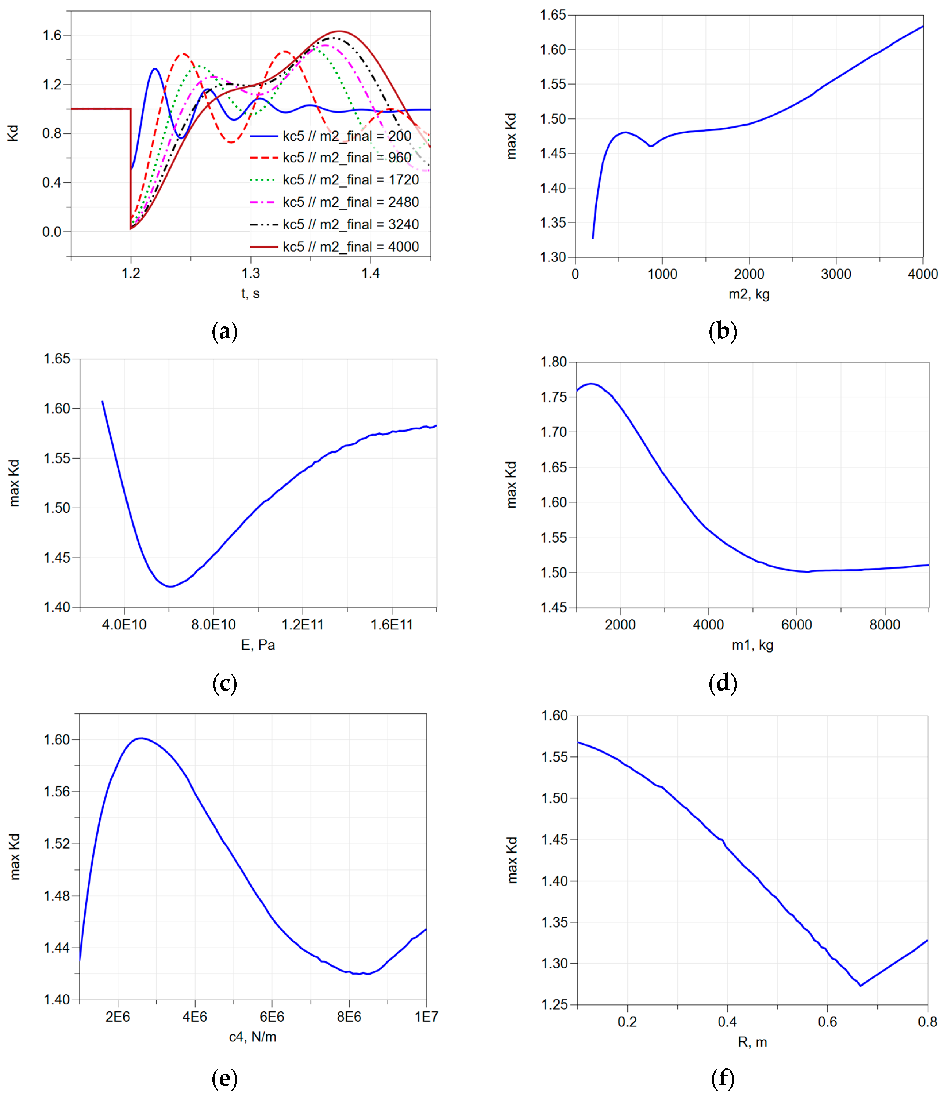
Parametric studies were carried out to determine the relationship between the maximum dynamic factor maxKd and the system parameters, with parameters changing within specified limits.
Figure 3a displays graphs of the dynamic factor values over time for various payload masses
m2 in the scenario with a slack rope. It can be observed that for a small payload mass (200 kg), the maximum dynamic factor is reached during the first oscillation peak. At approximately 960 kg, the maximum values are nearly identical for the first and second oscillations. As the mass increases further, the second peak becomes dominant. This shift occurs because at lower masses, damping plays a stronger role than inertial forces, causing subsequent oscillations to diminish. Additionally, as the payload mass increases, the oscillation frequency decreases, contributing to this behavior. This leads to the fact that the function
maxKd = f(
m2) is thus highly nonlinear and exhibits a cusp, as shown in
Figure 3b. Strong nonlinearity is also noticeable in the graphs of other parameters—
maxKd = f(
Er) is shown in
Figure 3c,
maxKd = f(
m1) is shown in
Figure 3d,
maxKd = f(
c4) is shown in
Figure 3e, and
maxKd = f(
R) is shown in
Figure 3f. Studying and drawing unambiguous conclusions about
maxKd in a wide range of changes in system parameters is difficult due to these facts. For this reason, a parametric study of
maxKd was conducted using narrower intervals of change in the system parameters, specifically ±20% of the nominal value of the parameter. In these intervals, the dependencies are either linear or can be approximated with high accuracy by a linear function.
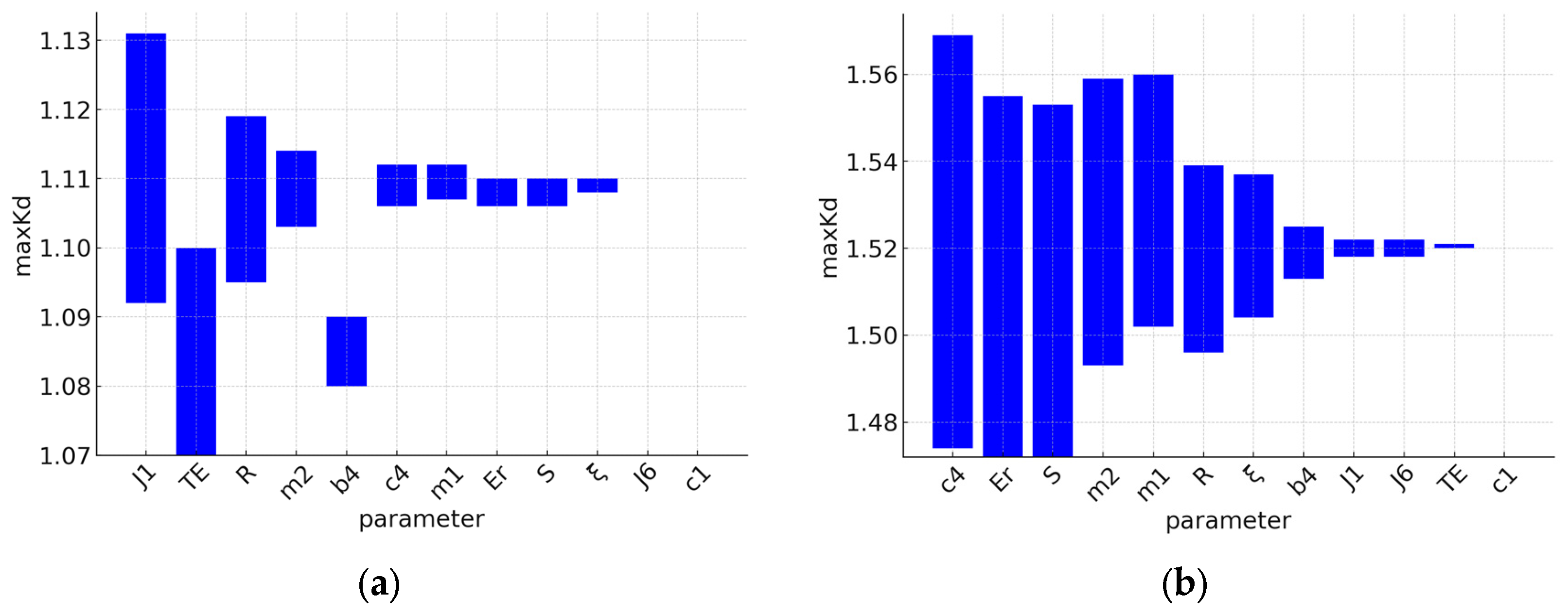
The results of the numerical experiments regarding the values of
maxKd (
for the tight rope scenario and
for the slack rope scenario) at the lower (
P − 20%) and upper (
P + 20%) limits of change in the system parameters are systematized in
Table 2. The ranked ranges of changes in the dynamic factor for the two scenarios being considered are shown in
Figure 4.
As one can see, the parameters have different influences on the
maxKd values. To determine the influence based on the data from
Table 2, a local normalized sensitivity was calculated for both scenarios (
and
, respectively). The following relationship determines it [
28]:
where
is the interval of change in the parameter,
is the interval of change in
,
is the average value of
in its interval of change, and
P is the nominal value of the parameter.
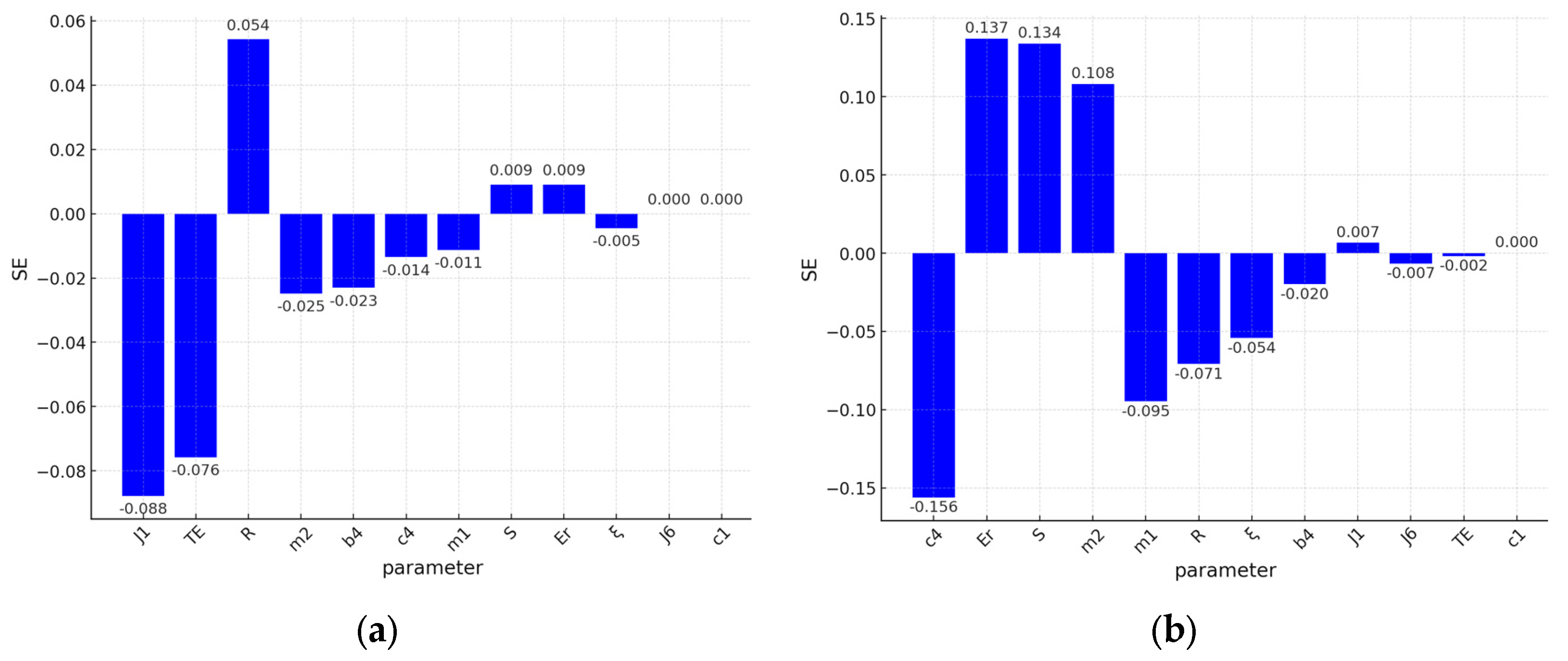
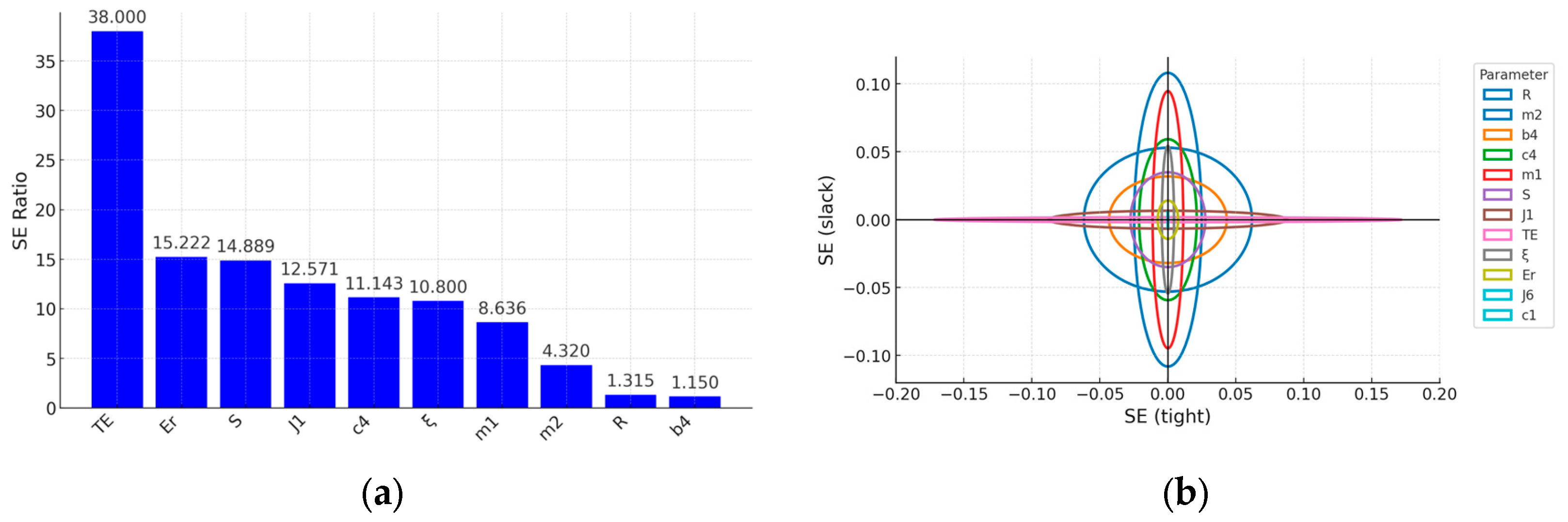
Figure 5a,b show the sensitivities determined by (14) for each parameter, ranked by value. The sensitivities have a positive or negative sign depending on whether
increases or decreases with increasing the parameter value. As seen, the sensitivities are different for the two operating scenarios. In
Figure 6a, the sensitivities ratio is shown, calculated by dividing the larger by the smaller value without considering their signs, i.e.,
.
Figure 6b shows the sensitivities of all parameters by visualizing them with ellipses, with semi-axes equal to the sensitivities in both scenarios. The ellipses should be circles if both scenarios of operation have the same sensitivity.
4. Discussion
From the analysis of the results in the considered range of parameter changes, it can be seen that the maximum value of the dynamic factor reaches 1.131 for the tight rope scenario (see
Figure 4a), while for the slack rope scenario, it increases to 1.569 (see
Figure 4b. The significant difference indicates that the slack rope mode results in significantly higher dynamic loads, which should be decisive for the sizing of the mechanism elements, as has been proven in [
14,
15]. Here, strong transients are caused by shock loading. The dynamic factor is influenced by a different set of parameters in both scenarios considered.
For the scenario of hoisting with a tight rope, the dynamic factor is determined primarily by the moment of inertia of the motor
J1 (see
Figure 5a), which, when increased, reduces the dynamic factor (has a negative sensitivity), primarily influencing the decrease in the starting accelerations of the system and giving the system greater stability to applied shock loads. The electromechanical constant of the motor
TE has a negative sensitivity—its increase leads to slower transient processes in the motor and, respectively, less dynamic load on the mechanical system components. Increasing the radius of the drum
R increases the dynamic factor (has a positive sensitivity) since its increase leads to an increase in the speed of hoisting the load and an increase in inertial forces. The mass of the payload
m2 has a weaker influence on the dynamic factor, which has a negative sensitivity. Increasing the system’s inertial characteristics by increasing
m2 while maintaining the motor’s power capabilities results in lower starting accelerations, which is the main reason for this. The other parameters examined have a less significant effect. In this mode, the rope parameters
Er and
S, which determine its stiffness and deformation, have little effect at positive sensitivity. The primary reason for this is that the stiffness of the rope increases due to the increase in these parameters, which, in turn, increases the dynamic factor. The movement of the payload begins with an already deformed rope that has accumulated potential energy, and transient dynamic processes only result in small additional deformations.
When hoisting with a slack rope, the dynamic factor is significantly higher and has greater sensitivity due to the more significant dynamic processes because of shock loading (see
Figure 5b). The analysis shows that in this scenario, the main influence is exerted by the mechanical system elements included in the vertical kinematic chain. The stiffness of the supporting structure
c4 and the mass of the metal structure
m1 have a strong influence and negative sensitivity. The main reason for this is that an increase in both parameters results in smaller crane vibration amplitudes and, in turn, smaller inertial forces that affect the dynamic factor. Increasing the payload mass
m2 increases the dynamic factor, since its value determines the inertial force and the magnitude of the impact load on the system at the moment of rope slack removal. The stiffness characteristics of the rope, defined by the modulus of elasticity
Er and the cross-section
S are also highly influential parameters with positive sensitivity. They determine the deformation of the rope, its ability to accumulate and release potential energy, and the magnitude of the impact reaction in it. The relative damping coefficient
is responsible for regulating the rate of oscillation damping and decreasing amplitude peaks. Unlike a tight rope scenario, with a slack rope, the drive parameters
J1 and
TE have a weak influence, since the motor only participates in the dynamics of the system after the initial impact. The radius of the drum
R, which, according to (12), determines the force in the rope, also has a negative sensitivity.
The analysis of the values of the sensitivity ratio from
Figure 6a shows that the sensitivities of
TE,
Er,
S,
J1,
,
c4,
m1, and
m2 change the most, i.e., these parameters influence the value of the maximum dynamic factor the most when the system loading mode changes.
By calculating Pearson’s linear correlation coefficients
r, we can determine the strength of the relationship between the input parameters and
maxKd. For this purpose, using the Monte Carlo method with 2 × 10
3 numerical experiments, all system parameters in
Table 2 were varied simultaneously, and
maxKd was determined for each combination.
Figure 7a shows the ranked statistically significant correlation coefficients
r for the scenario of hoisting with a tight rope, and
Figure 7b shows the same for the slack rope scenario. The values and their signs confirm the results of the sensitivity analysis. For the tight rope scenario,
J1 and
R have the strongest influence, and their correlation coefficients are −0.78 and 0.50 respectively. For the slack rope scenario, the strongest influence is seen for the parameters
c4,
S,
m2,
Er,
m1, and
R, with correlation coefficients of −0.48, 0.40, 0.40, 0.38, −0.36, and −0.24, respectively. The direction of the correlation coincides with that of the sensitivity.
Also, the obtained dataset was used to establish multiple linear regression models that determine the maximum dynamic factor for both scenarios, with only statistically significant coefficients included:
The equations’ adjusted coefficients of determination
R2 are 0.98 for the tight rope and 0.93 for the slack rope scenarios. To determine how much of the variation in
maxKd is caused by the variation in the corresponding parameter, a calculation of the partial coefficients of determination was also performed, the values of which are presented in
Table 3. The bolded values indicate the most significant values, and the results validate the results of the sensitivity and correlation coefficients analysis. In the tight-rope case, motor inertia
J1 and drum radius
R explain ≈64 % and ≈27 % of the
maxKd variance, respectively. In slack-rope hoisting, support-structure stiffness
c4, rope cross-section
S, and payload mass
m2 contribute ≈22%, ≈17% and ≈17%, respectively.
5. Conclusions
In this paper, a mathematical model of a hoisting mechanism is developed, which considers the inertial, elastic, and damping characteristics of the main elements of the system and the dynamic characteristics of the DC motor. With this model, one can accurately simulate transient processes, peak loads, and the system’s real dynamics under different operating conditions. A parametric study of the values of the dynamic factor in the rope has been conducted through numerical experiments. The simulations performed in a specific parameter range (±20% compared to their nominal values) reveal that the dynamic factor in the rope is strongly influenced by the mechanism’s operating mode. The dynamic response of the system in a tight rope hoisting is mostly determined by parameters that relate to the drive and kinematics, and the dynamic factor is relatively low.
But in the slack rope mode, a sharp increase in the dynamic factor and its sensitivity to changes in the system parameters is observed. Here, the parameters of the elements forming the kinematic chain in the vertical direction have a clear dominant influence. Key variables include the modulus of elasticity, rope cross-section, payload mass, and stiffness and mass of the supporting structure. In this mode, the elastic properties significantly impact the absorption and release of kinetic and potential energy, leading to a significant impact on the amplitude of transient processes and the amount of dynamic forces.
The results obtained show that the scenario of hoisting with a slack rope is relevant for the dimensioning of the hoisting system, since in this scenario the highest values of the dynamic factor and the highest peak loads are reached. This has practical significance in engineering practice, as it draws attention to the key design parameters that play a critical role in generating a higher dynamic factor and which must be carefully controlled and optimized to ensure reliability in the operation of the hoisting mechanisms. The developed approach for modeling and analyzing the dynamics of hoisting mechanisms provides a reliable basis for making engineering decisions, allowing for precise identification of critical factors and effective optimization of the system for different operating modes.
Future research will be directed to evaluate the effects of parametric uncertainties and consider different motor rotation laws. Experimental confirmation and model calibration will be carried out to correct model parameters and enhance the quality of dynamic predictions.


