Proceeding Paper

A Wind Tunnel Study of the Aerodynamic Characteristics of Wings with Arc-Shaped Wingtips †

by
Stanimir Penchev
1,2,* and
Hristian Panayotov
1,2
1
Department of Transport and Aircraft Equipment and Technologies, Technical University of Sofia, Plovdiv Branch, 4000 Plovdiv, Bulgaria
2
Center of Competence “Smart Mechatronic, Eco- and Energy Saving Systems and Technologies”, 4000 Plovdiv, Bulgaria
*
Author to whom correspondence should be addressed.
Presented at the 14th International Scientific Conference TechSys 2025—Engineering, Technology and Systems, Plovdiv, Bulgaria, 15–17 May 2025.
Eng. Proc. 2025, 100(1), 28; https://doi.org/10.3390/engproc2025100028
Published: 11 July 2025

Abstract

Wingtip devices like winglets and other types have been created to improve the aerodynamic efficiency of aircraft based on minimizing the induced drag of tip vortices. This study aims to investigate the aerodynamic characteristics of these devices at low Reynolds numbers. In the present study, the models of a basic non-swept tapered wing and a wing with arc-shaped wingtips are examined. For this purpose, the basic model is equipped with replaceable tips with different geometries. The measurements are performed in a low-speed wind tunnel at a Reynolds number of around 100,000. The analysis of the collected data shows that the best aerodynamic characteristics have a configuration with a 45-degree dihedral angle at the tips of the wing. These results can be used in the conceptual design of small unmanned aerial vehicles (UAVs) to improve their performance in terms of range and endurance.

1. Introduction

Wingtip devices are designed to improve the aerodynamic efficiency of aircraft by increasing lift, reducing drag, and decreasing the intensity of tip vortices. They have many variations and can be divided into three main groups: in the plane of the wing, flat, at an angle to the plane of the wing, and with a nonplanar shape [1]. These devices increase the effective aspect ratio of the wing and reduce induced losses, but on the other hand, they also increase parasitic drag. Another drawback is the increased mass of the wing due to augmented bending moment. The main task in the design process is to choose an aerodynamic layout that allows for the realization of a better flight performance. There are different types of wingtip devices [2], and the more common ones are shown in Figure 1.
Wind tunnel studies are one of the most widely used methods for determining the aerodynamic characteristics of wingtip devices [3,4,5,6]. The results of studies on a wing with elliptical winglets [7], multi-element winglet systems [8,9], and wing-grid tips with several elements and a semicircular planform [10] have been published. The data from these experiments show a significant increase in the lift-curve slope and the maximum lift-to-drag ratio.
The article presents a comparative wind tunnel study of the aerodynamic characteristics of models with a tapered planar wing and winglet configurations at low Reynolds numbers.
The research was carried out at the Laboratory of Aerodynamics in the Plovdiv branch of the Technical University of Sofia. Based on the results of the experiments, a comparison of the aerodynamic characteristics of the different configurations was made.

2. Materials and Methods

2.1. Model Details

The wind tunnel model consists of several parts—a cylindrical body, two wing consoles, and replaceable tips. This design allows for obtaining many variants with a minimum number of manufactured parts.
The non-swept base wing has a trapezoidal plane shape, with a wingspan of 400 mm, a root chord of 60 mm, a tip chord of 40 mm, a mean geometric chord of 50 mm, a taper ratio of 0.67, an aspect ratio of 8, and a reference wing area of 0.02 m2, without geometric washout. The cross-sections of the wing and the wingtip devices are made of airfoil NACA0012. The diameter of the body is 53.5 mm, and the length is 384 mm.
The wingtips have an arc-shaped form as shown in Figure 2. The trailing edge of the wing model (t.e.) is straight, and the leading edge (l.e.) has an increased sweep angle. The cant angle is denoted as θ.
The releasable parts of the wind tunnel model are made by the rapid prototyping technology Fused Deposition Modelling (FDM), which uses polymers (mainly ABS) suitable for both prototypes and final products. The obtained parts are appropriate both for conducting functional tests and for use as final products. They have a good appearance, which can be subjected to further processing. Before the test, the manufacturing details are additionally taken into account in order to improve their surface quality and obtain the necessary smoothness.
Additional pre-fabricated aerodynamic surfaces have been mounted to the wing consoles of the multiple-part model, and thus, various configurations have been obtained. The use of symmetrical airfoils and the absence of geometric washout allows for easier arrangement. Three-dimensional models in the SolidWorks 2022 have been developed (Figure 3).
Three different values and two directions for the cant angle are used. Negative values have the wingtips pointing downwards (Table 1).

2.2. Wind Tunnel and Instrumentation

A low-speed closed-circuit wind tunnel with a 600 mm × 400 mm open rectangular test section and a length of 1000 mm was used for carrying out the experiments (Figure 4). The wind tunnel can be operated at a maximum airspeed of 50 m/s and has a capacity for setting an angle of attack from minus 10° to 20°. Detailed data on the design and characteristics of the test facility are given in [11].
Internal strain gage aerodynamic balances [12] directly measure the forces and moments in the coordinate system of the balances: axial force X, normal force Z, and pitch moment M.
During the experiment, the following is carried out: automated control of the model’s movement according to a preset program; automated output of information with strain gauges, a flow temperature sensor, and sensors for measuring the total pressure and the differential pressure; and data processing and visualization.

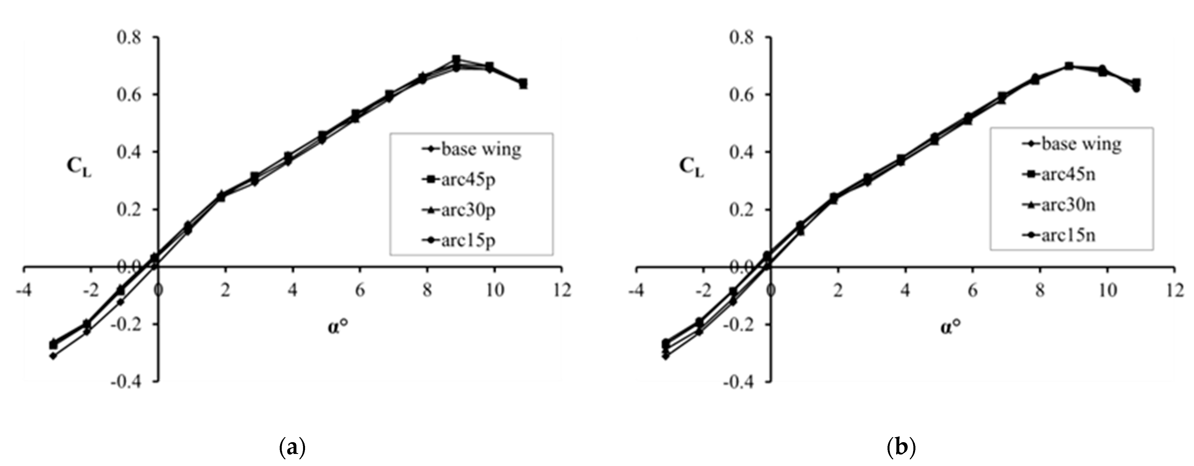
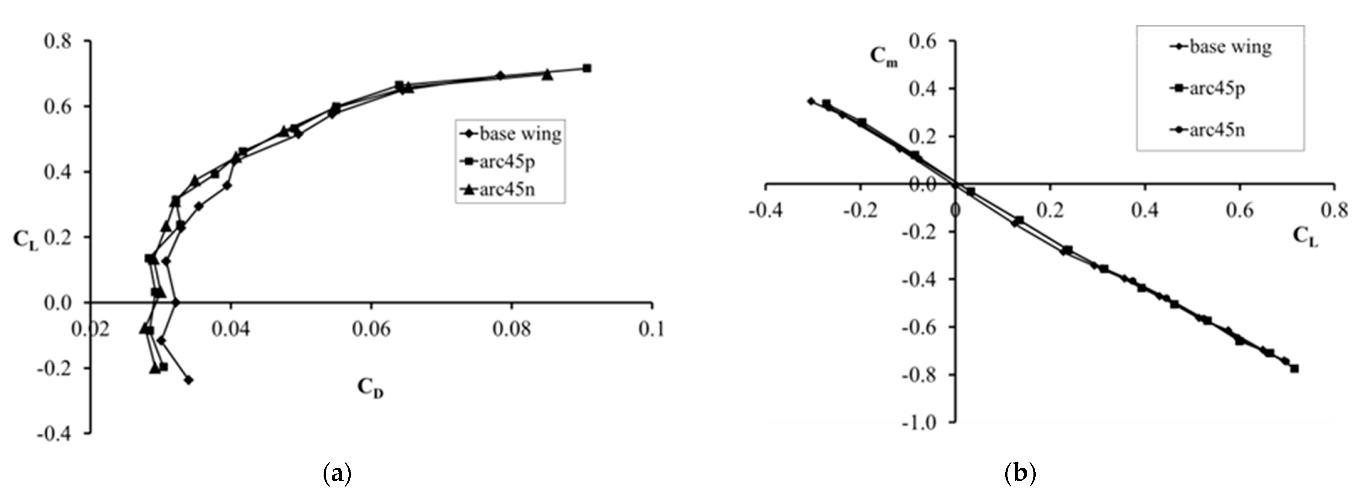
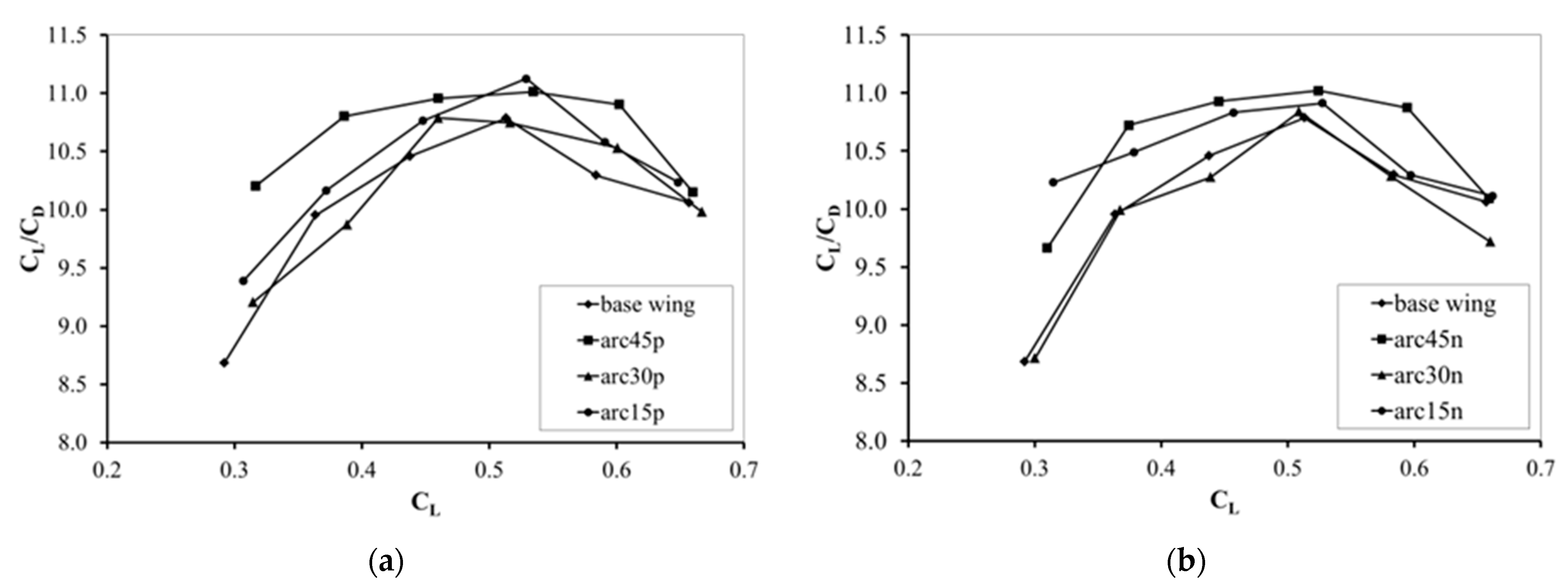
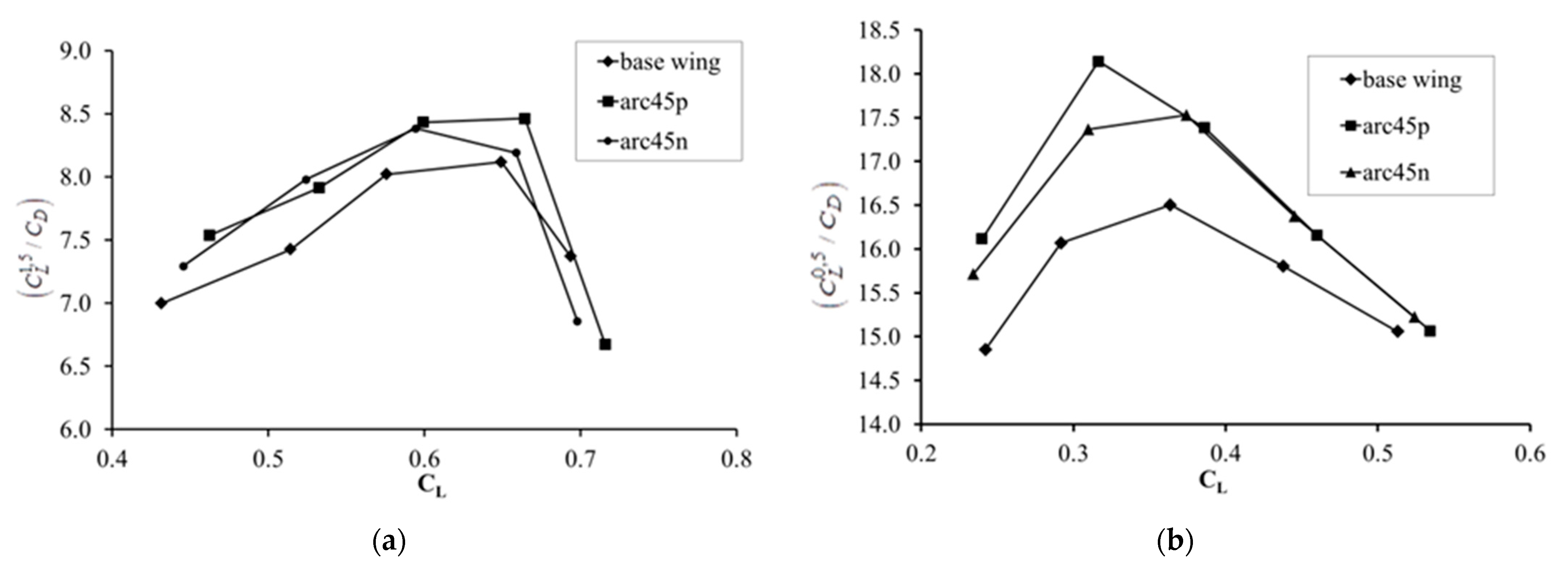
3. Results and Discussion

The conditions under which the wind tunnel tests were carried out were a constant flow speed of 25 m/s and a change in the angle of attack from 2° to 12° with increments of 1°. These conditions correspond to Reynolds numbers of around 100,000, which were calculated using the base wing’s mean chord. The effective Reynolds number according to [13] is 180,000. The experiments determined the aerodynamic forces and the moment in the plane of symmetry of the model—lift, drag, and pitch moment. The origin of the related coordinate system of the model coincides with the origin of the root chord of the wing. The obtained results are adjusted by introducing a correction for the downwash angle in the test section [11]. The lift force coefficient CL, drag force coefficient CD, and pitch moment coefficient Cm are calculated.
The data presented in Figure 5 shows the same values of stall angles of attack and negligible variation for maximum lift coefficients. The lift-curve slope is less than that of the base wing.
The minimum drag coefficients (Figure 6a) are almost the same and lower than those of the base wing. One of the reasons for this is that the same reference wing area, equal to that of the base wing, is used for the aerodynamic performance calculation.
There is practically no change in the pitch moment for different configurations (Figure 6b).
At a maximum lift-to-drag ratio, the minimum required thrust for level flight is obtained, i.e., the maximum endurance with all other things being equal. To evaluate the aerodynamic efficiency at angles of attack smaller and larger than the most advantageous one, coefficients C1 and C2 were calculated.
C 1 = C L 1.5 C D ,
C 2 = C L 0.5 C D
The maximum values of these coefficients correspond to the modes of the minimum required power for level flight and maximum flight range [14]. During the first of these modes, the angle of attack is larger than the most advantageous one, while during the second, it is smaller, and so is the lift coefficient. The calculation of these quantities and the comparison of their values with the values for the base wing will allow for evaluating the possibilities of increasing the flight performance of aircraft using the studied aerodynamic characteristics.
The change in the lift-to-drag ratio (Figure 7) is smoother and, in the range from 0.3 to 0.7 of CL, it has higher values for configurations with a ±45° cant angle compared to the base wing. At a lift coefficient of around 0.5, the maximum values are observed. The increase is less than 4% compared to the baseline model.
The change in coefficients C1 and C2 (Figure 8) is more significant. At a lift coefficient of around 0.65, the maximum values of coefficient C1 are observed, and the increase is about 4%. The maximum values of coefficient C2 have the highest rise compared to the base wing. For configurations with a ±45° cant angle, the increase is up to 8%. The lift coefficient for these conditions has values slightly above 0.3.
Table 2 presents the calculated values of the aerodynamic characteristics for the studied configurations. The lift-curve slope is estimated for positive lift coefficients in the linear range. The stall angle of attack for all configurations is around 9°.

4. Conclusions

Based on the research conducted and the results obtained, the following main conclusions can be drawn:
  • The winglet models with a ±45° cant angle have increased lift-to-drag ratios, minimum power, and maximum range coefficients.
  • It cannot be clearly determined whether configurations with positive or negative dihedral angles have better characteristics.
  • The results show that winglet models have a greater increase in aerodynamic efficiency at low angles of attack.
The latter observation is interesting from an aerodynamic point of view and needs further investigation. To clear up the influence of the winglet’s dihedral, further studies for models with cant angles of 60° to 90° are required.
The results of this research can be used to create computational models to study the influence of geometric parameters such as twist, chord distribution, etc., and achieve an optimal winglet design. Another application of the obtained experimental data is in the development process of small UAVs.

Author Contributions

Conceptualization, S.P.; methodology, S.P. and H.P.; software, S.P. and H.P.; validation, S.P.; formal analysis, S.P.; investigation, S.P.; resources, S.P. and H.P.; data curation, S.P.; writing—original draft preparation, S.P.; writing—review and editing, H.P.; visualization, S.P.; supervision, H.P.; project administration, H.P.; funding acquisition, H.P. All authors have read and agreed to the published version of the manuscript.

Funding

This research was funded by the European Regional Development Fund within the OP “Research, Innovation and Digitalization Programme for Intelligent Transformation 2021–2027”, Project CoC “Smart Mechatronics, Eco- and Energy Saving Systems and Technologies”, No. BG16RFPR002-1.014-0005.

Institutional Review Board Statement

Not applicable.

Informed Consent Statement

Not applicable.

Data Availability Statement

Data are contained within the article.

Conflicts of Interest

The authors declare no conflicts of interest.

References

  1. Penchev, S. Study of Aerodynamic Characteristics of Wings with Wingtip Devices. Ph.D. Thesis, Technical University—Sofia, Sofia, Bulgaria, 2018. [Google Scholar]
  2. Raymer, D.P. Aircraft Design: A Conceptual Approach, 5th ed.; AIAA Education Series; American Institute of Aeronautics and Astronautics Inc.: Washington, DC, USA, 2012. [Google Scholar]
  3. Inam, M.I.; Mashud, M.; Nahian, A.; Selim, S.M. Induced drag reduction for modern aircraft without increasing the span of the wing by using winglet. Int. J. Mech. Mechatron. 2010, 10, 49–53. [Google Scholar]
  4. Nikolic, V.R. Planform variations and aerodynamic efficiency of movable tip strakes. J. Aircr. 2007, 44, 340–343. [Google Scholar] [CrossRef]
  5. Nikolic, V.R. Effect of leading-edge form on performance of wing-movable tip strake configurations. J. Aircr. 2007, 44, 1749–1753. [Google Scholar] [CrossRef]
  6. Reeder, M.F.; Allen, W.; Phillips, J.M.; Dimmick, R. Wind-tunnel measurements of the E-8C modeled with and without winglets. J. Aircr. 2008, 45, 345–348. [Google Scholar] [CrossRef]
  7. Arora, P.R.; Hossain, A.; Edi, P.; Jaafar, A.A.; Younis, T.S.; Saleem, M. Drag reduction in aircraft model using elliptical winglet. J.-Inst. Eng. 2005, 66, 1–8. [Google Scholar]
  8. Berens, M. Potential of Multi-Winglet Systems to Improve Aircraft Performance. Ph.D. Thesis, Technical University Berlin, Berlin, Germany, 2008. [Google Scholar]
  9. Catalano, F.M.; Ceron-Munoz, H.D. Experimental analysis of aerodynamic characteristics of adaptive multi-winglets. Proc. Inst. Mech. Eng. Part G J. Aerosp. Eng. 2006, 220, 209–215. [Google Scholar] [CrossRef]
  10. Hossain, A.; Rahman, A.; Iqbal, A.; Ariffin, M.; Mazian, M. Drag analysis of an aircraft wing model with and without bird feather like winglet. Int. J. Aerosp. Mech. Eng. 2012, 6, 8–13. [Google Scholar]
  11. Panayotov, H.; Penchev, S.; Kolibarov, D. Experimental study of canard UAV aerodynamics. MATEC Web Conf. 2017, 133, 01002. [Google Scholar] [CrossRef]
  12. Britcher, C.; Landman, D. Wind Tunnel Test Techniques, 1st ed.; Academic Press: Cambridge, MA, USA, 2023. [Google Scholar]
  13. Panayotov, H.; Penchev, S.; Zikyamov, M. Experimental study of turbulence in the test section of wind tunnel. In Proceedings of the 15th International Scientific and Practical Conference “Environment. Technology. Resources”, Rezekne, Latvia, 27–28 June 2024; Volume 3, pp. 217–220. [Google Scholar] [CrossRef]
  14. Torenbeek, E.; Wittenberg, H. Flight Physics. Essentials of Aeronautical Disciplines and Technology with Historical Notes; Springer: London, UK, 2009. [Google Scholar]
Figure 1. Common view of wingtip devices.
Engproc 100 00028 g001
Figure 2. Schematic diagram of the winglet design.
Engproc 100 00028 g002
Figure 3. Three-dimensional representation of half-wing models.
Engproc 100 00028 g003
Figure 4. Aircraft model mounted in the wind tunnel test section.
Engproc 100 00028 g004
Figure 5. Lift coefficient vs. angle of attack for (a) wingtips with positive dihedral angles and (b) wingtips with negative dihedral angles.
Engproc 100 00028 g005
Figure 6. Aerodynamic characteristics for selected configurations: (a) drag polar; (b) pitch moment coefficient.
Engproc 100 00028 g006
Figure 7. Lift-to-drag ratio vs. lift coefficient: (a) wingtips with positive dihedral angles; (b) wingtips with negative dihedral angles.
Engproc 100 00028 g007
Figure 8. Aerodynamic characteristics for selected configurations: (a) variation in coefficient C1 vs. lift coefficient; (b) variation in coefficient C2 vs. lift coefficient.
Engproc 100 00028 g008
Table 1. Data for the test models.
Test ModelsCant Angle θDesignation
Base wingbase wing
Wing with winglets15°arc15p
30°arc30p
45°arc45p
−15°arc15n
−30°arc30n
−45°arc45n
Table 2. Aerodynamic characteristics and summary of results.
Test ModelsCLmaxCLα(CL/CD)maxC1C2
Base wing0.704.3010.658.1116.21
arc15p0.694.2411.138.2416.95
arc30p0.714.1610.788.1916.41
arc45p0.724.4711.088.4617.44
arc15n0.704.2310.937.9116.60
arc30n0.704.2810.847.9516.47
arc45n0.704.3311.028.3817.52
Disclaimer/Publisher’s Note: The statements, opinions and data contained in all publications are solely those of the individual author(s) and contributor(s) and not of MDPI and/or the editor(s). MDPI and/or the editor(s) disclaim responsibility for any injury to people or property resulting from any ideas, methods, instructions or products referred to in the content.

