
Modelling and Optimization of the Precision Hot Forging/Extrusion Process of an Asymmetric C45E/1.1191 Carbon Steel Bearing Element †


Abstract
1. Introduction
Main Characteristics of the Process
- Extrusion ratio
- True strain
- Degree of reduction
2. Methods and Materials

| Standarts | DIN | AISI | JIS | GOST | Grade (UNS) | |
|---|---|---|---|---|---|---|
| Tool 1 | X155CrVMo12-1 | 1.2379 | D2 | SKD11 | Х12МФ | D2 |
| Tool 2 | X37CrMoV5-1 | 1.2343 | H11 | SKD6 | 4ХМФ6C | H11 |
| Workpiece | C45 | 1.0503 | C45 | 1.0503 | C45 | 1.0503 |
| Standard | Steel Number (Name) | C | Si | Mn | P, ≤ | S, ≤ | Cr | Ni | Mo | V | Cr + Mo + Ni |
|---|---|---|---|---|---|---|---|---|---|---|---|
| EN ISO 4957 [19] | 1.2343 (X37CrMoV5-1) | 0.33–0.41 | 0.90–1.20 | 0.25–0.50 | 0.03 | 0.02 | 4.8–5.5 | 1.10–1.50 | 0.30–0.50 | ||
| EN 10083-2 [20] | 1.0503 (C45) | 0.42–0.50 | 0.40 | 0.50–0.80 | 0.045 | 0.045 | 0.40 | 0.40 | 0.10 | 0.63 |
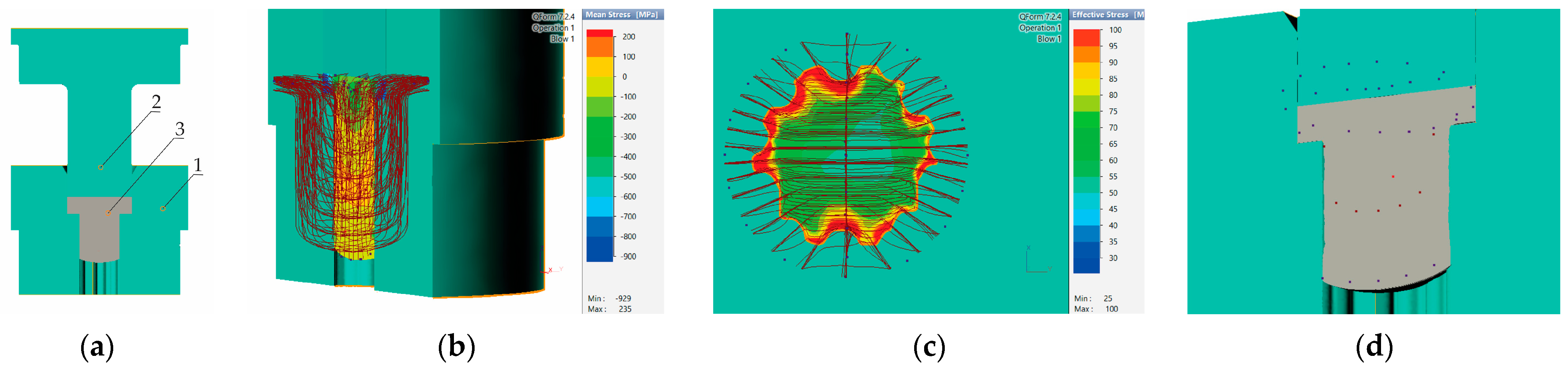
3. Simulation
3.1. Initial Boundary Conditions for Numerical Modeling of an Asymmetric Model Using the Precision Extrusion Forging Method
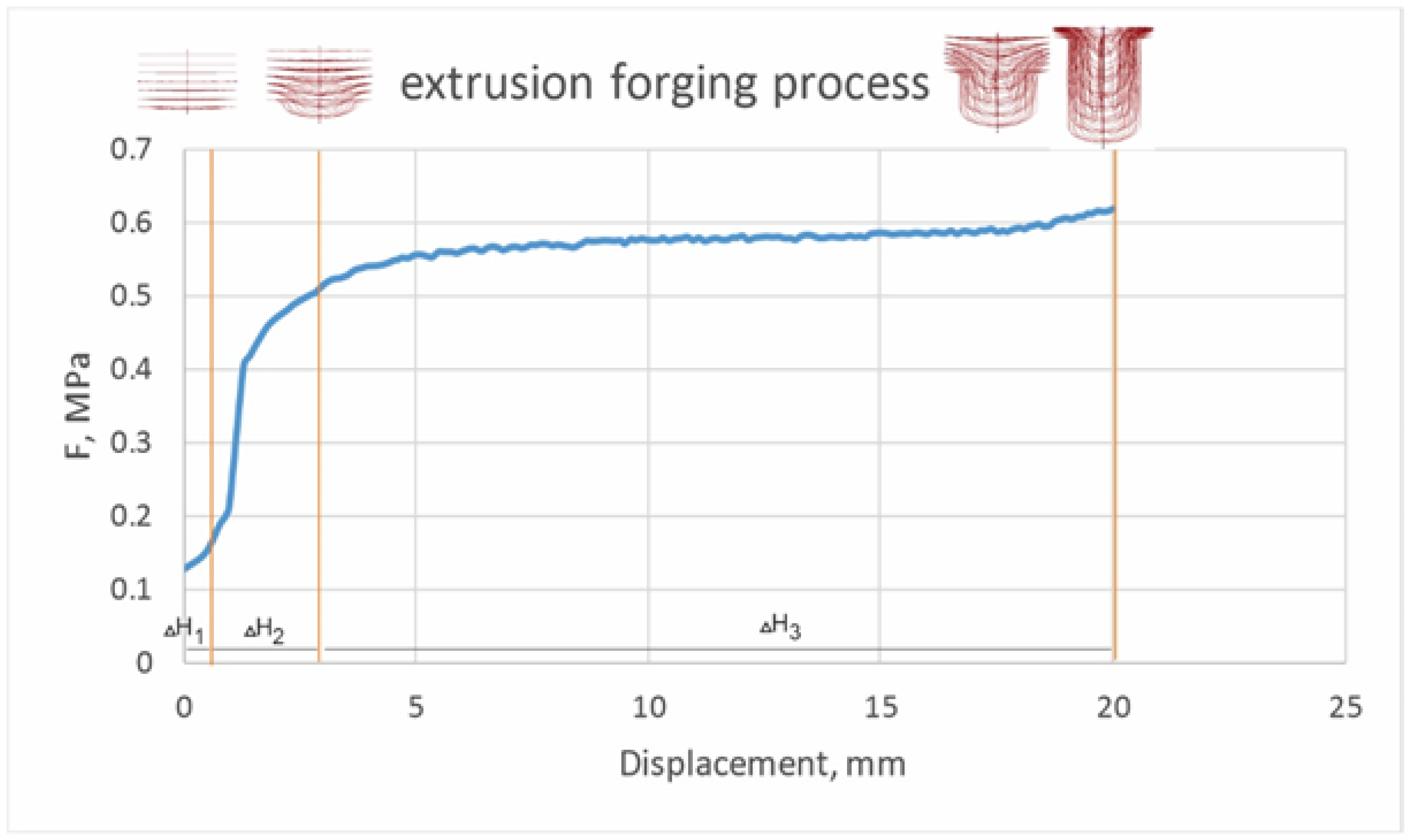
3.1.1. Limit Values for Speed Based on the Specific Speed of the Punch
- -
- Punch speed ν = 0.15 m/s
- -
- Speed of the deformed workpiece W = (So/S1)ν [m/s]
3.1.2. Limit Values for Temperatures and Tribological Conditions
- -
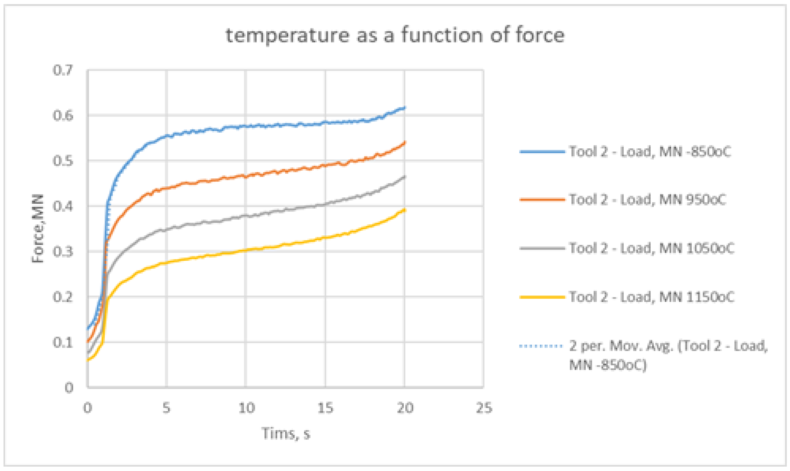
- Nominal charging temperatures 850 °C, 950 °C, 1050 °C, and 1150 °C.
- -
- Ambient temperature 20 °C.
- -
- Tool temperature 250 °C.
- -
- Tool thermal conductivity 30 W/m.K.
- -
- Hydraulic press with a nominal value of 120 MN—selected from the software database.
- -
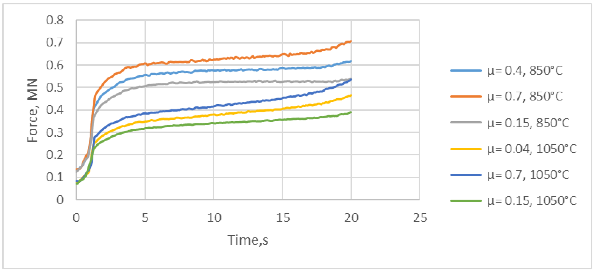
- Friction coefficients 0.15 glass, 0.4 graphite and water, and 0.7 saline solution.
- -
- Levanov coefficient 1.25.
- -
- 850 °C—min. temperature for the specific steel for hot deformation.
- -
- 950 °C—step 100 °C.
- -
- 1050 °C—step 100 °C.
- -
- 1150 °C—max. temperature for the specific steel for hot deformation.
- -
- 0.15 glass, 850 °C/1050 °C.
- -
- 0.4 graphite and water, 850 °C/1050 °C.
- -
- 0.7 salt solution, 850 °C/1050 °C.
- -
- An increase in the maximum temperature was observed at all four temperatures of the initial billet (Table 3), with the highest increase occurring at the workpiece with the lowest temperature of 850 °C, which was most likely due to the difficult passage of the metal into the deformation zone [21] and slower recrystallization processes.
- -
- A probable reason for the increase in temperature may be high friction, which made it difficult for the deformed flow to pass due to the small radius of roundness of the die.
- -
- Around the punch and die, in areas where the metal was static, cooling of the part was observed (Figure 3), and in areas where the metal was most intensely deformed, the temperature rose.
- -
- At the end of these processes, the lower end of the workpiece was the most overcooled in all four simulations.
4. Results
- -
- With the help of a robot, the workpiece was positioned under the inductor (Figure 4a).
- -
- The inductor was in the lower position and heated the workpiece to the desired temperature (Figure 4a).
- -
- -
- A working stroke and extrusion forging followed.
- -
- The robot took the finished forging (Figure 4c) and transported it to the container of finished products.
5. Conclusions
- -
- The specific technology is very complex to implement in industrial conditions, as even small changes in the optimal parameters of the technological process can lead to poor-quality parts.
- -
- The analyses conducted with QForm 7.2.4 established that a change in the charging temperature in the range of 850–1150 °C with a step of 100 °C affected both the power and tribological parameters and facilitated a change in the temperature of the tools.
- -
- The temperature of the tool matrix is a key factor in obtaining defect-free forgings in combination with many factors such as the temperature of the workpiece, extrusion forging speed, flow rate in the deformation space, and lubricant.
- -
- As increasing heat was applied to the workpiece, the temperature of the die increased and the lubricant failed to prevent additional heating of the contact surface of the die, which is why the lowest possible temperature is recommended for the production process.
- -
- The developed technology for precision extrusion forging allows defect-free and waste-free production.
- -
- Simulation results in the QForm 7.2.4 environment proved to be in good agreement with the results of the manufacturing process.
Author Contributions
Funding
Institutional Review Board Statement
Informed Consent Statement
Data Availability Statement
Acknowledgments
Conflicts of Interest
References
- Suris, J.A.; Yurgel, C.C.; Alves de Sousa, R. Influence of the Grain-Flow Orientation after Hot Forging Process Evaluated through Rotational Flexing Fatigue Test. Metals 2023, 13, 187. [Google Scholar] [CrossRef]
- Hawryluk, M.; Jakubik, J. Analysis of forging defects for selected industrial die forging processes. Eng. Fail. Anal. 2016, 59, 396–409. [Google Scholar] [CrossRef]
- Lange, K.; Cser, L.; Geiger, M.; Kals, J.A.G. Tool Life and Tool Quality in Bulk Metal Forming. CIRP Ann.-Manuf. Technol. 1992, 41, 667–675. [Google Scholar] [CrossRef]
- Tomczak, J.; Pater, Z.; Bulzak, T. Designing of screw impressions in the helical rolling of balls. Arch. Civ. Mech. Eng. 2014, 14, 104–113. [Google Scholar] [CrossRef]
- Gronostajski, Z.; Kaszuba, M.; Hawryluk, M.; Zwierzchowski, M. A review of the degradation mechanisms of the hot forging tools. Arch. Civ. Mech. Eng. 2014, 14, 528–539. [Google Scholar] [CrossRef]
- Marchev, K.; Petrov, K.; Sofronov, Y.; Rayna Dimitrova, R.; Nikolov, A.; Lyutov, G.; Angelov, M.; Milchev, R. Prediction of defects in gravity casting by simulation modeling. AIP Conf. Proc. 2025, 3274, 070008. [Google Scholar] [CrossRef]
- Bay, N. New lubricant systems for cold and warm forging–advantages and limitations. In Proceedings of the 12th International Cold Forging Congress, Stuttgart, Germany, 17–18 May 2011. [Google Scholar]
- Hirscvogel, M.; Dommelen, H.V. Some applications of cold and warm forging. J. Mater. Process. Technol. 1992, 35, 343–356. [Google Scholar] [CrossRef]
- Colin, S.H. A review of automation in manufacturing illustrated by a case study on mixed-mode hot forging. Manuf. Rev. 2014, 1, 15. [Google Scholar]
- Available online: https://www.jerko-kempen.de (accessed on 2 May 2025).
- Ngaile, G.; Saiki, H.; Ruan, L.; Marumo, Y.A. Tribo-testing method for high performance cold forging lubricants. Wear 2007, 262, 684–692. [Google Scholar] [CrossRef]
- Bay, N. New tribo-system for cold forging of steel, stainless steel and aluminum alloys. In Proceedings of the 46th ICFG Plenary Meeting, Paris, France, 15–18 September 2013; pp. 171–178. [Google Scholar]
- Shivpuri, R.; Satish, K. Lubricants and Their Applications in Forging. In Metalworking: Bulk Forming; ASM International: Novelty, OH, USA, 2005; Volume 14A. [Google Scholar]
- Ghalehbandi, S.; Biglari, F. Predicting damage and failure under thermomechanical fatigue in hot forging tools. Eng. Fail. Anal. 2020, 113, 104545. [Google Scholar] [CrossRef]
- Rajiev, R.; Sadagopan, P. Simulation and Analysis of hot forging dies for Pan Head bolt and insert component. Mater. Today Proc. 2018, 5, 7320–7328. [Google Scholar] [CrossRef]
- Chastel, Y.; Caillet, N.; Bouchard, P.-O. Quantitative analysis of the impact of forging operations on fatigue properties of steel components. J. Mater. Process. Technol. 2006, 177, 202–205. [Google Scholar] [CrossRef]
- Navas, V.G.; Gonzalo, O.; Quintana, I.; Pirling, T. Residual stresses and structural changes generated at different steps of the manufacturing of gears: Effect of banded structures. Mater. Sci. Eng. A 2011, 528, 5146–5157. [Google Scholar] [CrossRef]
- Тoмoв, Б. Технoлoгия и Инструментална Екипирoвка за Обранoтване на Металите чрез Пластична дефoрмация; Русенски университет: Ruse, Bulgaria, 1981; pp. +172, Учебник за Студенти oт ВИММЕСС-Русе; част 1. [Google Scholar]
- EN ISO 4957:2018; Tool Steels (ISO 4957:2018). The European Committee for Standardization (CEN): Brussels, Belgium, 2018.
- EN ISO 683-1:2018; Heat-Treatable Steels, Alloy Steels and Free-Cutting Steels—Part 1: Non-Alloy Steels for Quenching and Tempering (ISO 683-1:2016). The European Committee for Standardization (CEN): Brussels, Belgium, 2016.
- Scapin, M.; Verleysen, P.; Hokka, M.; Bahlouli, N. Temperature Dependence of Material Behaviour at High Strain-Rate. J. Dyn. Behav. Mater. 2019, 5, 197. [Google Scholar] [CrossRef]


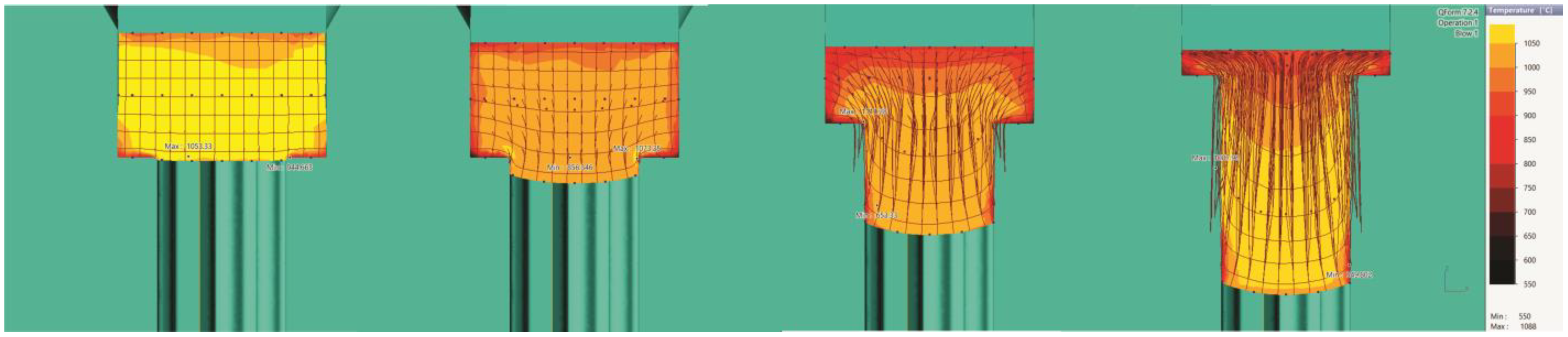

| Temperature | 850 | 950 | 1050 | 1150 | 850 |
| Maximum | 961.55 | 1018.73 | 1091.2 | 1177.91 | 961.55 |
| Minimum | 542.33 | 579.56 | 614.9 | 661.71 | 542.33 |
Disclaimer/Publisher’s Note: The statements, opinions and data contained in all publications are solely those of the individual author(s) and contributor(s) and not of MDPI and/or the editor(s). MDPI and/or the editor(s) disclaim responsibility for any injury to people or property resulting from any ideas, methods, instructions or products referred to in the content. |
© 2025 by the authors. Licensee MDPI, Basel, Switzerland. This article is an open access article distributed under the terms and conditions of the Creative Commons Attribution (CC BY) license (https://creativecommons.org/licenses/by/4.0/).
Share and Cite
Nikolov, A.; Mihaylov, A.; Yankov, D. Modelling and Optimization of the Precision Hot Forging/Extrusion Process of an Asymmetric C45E/1.1191 Carbon Steel Bearing Element. Eng. Proc. 2025, 100, 22. https://doi.org/10.3390/engproc2025100022
Nikolov A, Mihaylov A, Yankov D. Modelling and Optimization of the Precision Hot Forging/Extrusion Process of an Asymmetric C45E/1.1191 Carbon Steel Bearing Element. Engineering Proceedings. 2025; 100(1):22. https://doi.org/10.3390/engproc2025100022
Chicago/Turabian StyleNikolov, Antonio, Anton Mihaylov, and Dimiter Yankov. 2025. "Modelling and Optimization of the Precision Hot Forging/Extrusion Process of an Asymmetric C45E/1.1191 Carbon Steel Bearing Element" Engineering Proceedings 100, no. 1: 22. https://doi.org/10.3390/engproc2025100022
APA StyleNikolov, A., Mihaylov, A., & Yankov, D. (2025). Modelling and Optimization of the Precision Hot Forging/Extrusion Process of an Asymmetric C45E/1.1191 Carbon Steel Bearing Element. Engineering Proceedings, 100(1), 22. https://doi.org/10.3390/engproc2025100022