Abstract
Sensors are devices that measures a change in physical stimulus by converting it into an electronic signal which can be read by a designated instrument. To overcome the real-life challenges associated with powering a sensor using conventional batteries and chargers, this work focuses on formulating analytical framework for designing an ecofriendly, cheap, almost zero retrofit implication (except on damage) power module for sensors using an electromagnetic vibration energy harvester. This principle relies on the electromagnetic transduction whose harvested voltage/power is formulated from Faraday law of electromagnetic induction. An electromagnetic parameter that determines the degree of transduction is the coupling constant. The value of coupling constant must be accurately set during harvester design because it directly determines harvester damping ratio and the power available for the sensor. All parameters used to compute the coupling except the flux density are constant. In this work, we focus on formulating a set of analytical equations that could effectively determine the harvester’s optimum magnetic flux parameter to be used in computing the optimum coupling constant, the electromagnetic damping ratio, and the harvested power at resonant. This work concludes that the degree of coupling for the determined optimum flux density increases with an increased load resistance and hence larger harvested power is available to power the sensor.
1. Introduction
Structural health monitoring relies on the automatic detection of anomalous behavior of structures. Any localized damage in a structure reduces the stiffness, thereby increasing damping in the structure. Reduced stiffness and/or reduced damping causes a decrease in the natural frequencies and hence a modification of the vibration modes of the structure. An effective study of this dynamic characteristic is very important as a robust method for quantifying assurance of their integrity and mechanical health because an unpredicted failure may be devastating on economic, social, and human life. However, the need to power these SHM devices/sensors remotely and autonomously in a passive, efficient, ecofriendly way with minimum retrofitting cost is a major desire of sensor users in recent decades. A device that takes care of such power requirement is the vibration energy harvester.
Most convectional sensors have shown limitations with their usage since in most cases they are powered by batteries [1]. Retrofit cost and loss of information/data during this avoidable down time in cases of battery failure are the most notable among these limitations. Hence, there arose the need for an autonomous sensing regime where the sensor is continuously and sufficiently self-powered.
One different method of structural health monitoring, the use of fiber optics which uses guided light as a probe, has proven to be an efficient approach for sensing because it is easy to retrofit, non-electric, immune to electromagnetic interference, has high sensitivity and employs a nondestructive approach during installations [2,3] but the cost of achieving and maintaining such a pristine technology is expensive. One review [4] highlights the use of carbon nanomaterials as deposition materials for fiber reinforcements as another novel method for monitoring structural health during manufacturing and in-service life. Structural health monitoring of a structure is very important since their safety directly impacts the reliability of the structure [5]. Strategies employed to monitor structure health against seismic and severe climatic and human actions has been discussed [6] while analytical approach for quantifying the cost-benefit optimization using a stochastic methodology to optimally design structural health monitoring systems is given in [7].
A simple power module that has shown potential to powering SHM devices/sensors, microelectronics, and body interface gadgets remotely and autonomously is the vibration energy harvester, configured to harvest and convert ambient vibrational energy into electrical energy. Vibrations in structures can be induced by externally excited or self-excited dynamic factors. Vibration measurements have been conducted on varieties of structure; an example is the dynamic strain measurements in piezoelectric devices as reported by Meiqi et al. [8]. While different methodologies for vibration harvesting have been reported, most of the designs have either or both limited harvestable power and low operational bandwidth as limitations. This work aims to theoretically illustrate the necessary conditions for ensuring that maximum power is not only harvested but also available to sensor nodes by optimizing the harvester electrical parameters, such as the coupling value, electromagnetic damping ratio, and flux density, while noting how each optimized parameter determines the power harvested in relation to the load resistance.
A review on the development of energy harvesting for low power embedded structural health monitoring sensing systems was undertaken with emphasis on the past and prospects for powering sensor nodes [9]. Transduction methodology for the electromagnetic energy harvesting depends on the electromagnetic coupling which is the link between the motion and the induced voltage as well as the current and the Lorentz force [10]. Four different methods of measuring the coupling constants were mentioned [11,12] and one such method is herein employed for this work. An investigation of the electromechanical coupling effect of a hybrid electromagnetic and piezoelectric energy harvester [13] reported that the bigger the coupling coefficient, the greater the resonant frequency shift, output power, and conversion efficiency, with the hybrid energy harvester performing better than those of the two separate energy harvesting techniques in the weak coupling and medium coupling and vice versa in strong coupling. The effect of coupling strength on the efficiency of the electromagnetic energy harvester was shown in [14] concluding that, up to a certain point, increasing the coupling strength of the harvester substantially increases the output power, hence an improved device efficiency [14].
The focus in this work is on formulating an analytical equation for characterizing the harvester’s optimum magnetic flux parameter to be used in computing the optimum coupling factor, electromagnetic damping ratio, and maximum resonant power. Also, this work gives a vivid description of the way these parameters affect the size of the effective resistance of the sensor node.
2. Determination of the Harvester’s Resonant Frequency
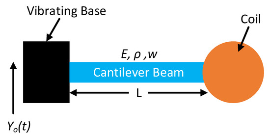
To properly define the harvester’s resonant frequency, it is modelled as a fixed-free Single Degree of Freedom tip loaded beam as shown in Figure 1. The beam is modelled so that one end is fixed to a base. The transverse motion equation of the clamped-free cantilever beam excited in harmonic at base position x and time t can be described by the following equation.
where is the absolute vertical beam displacement, is the vertical beam displacement relative to the fixed/clamped base, is the vertical amplitude base excitation, h is the thickness of beam, is the density of the beam, is the width of the beam, is the young modulus of the beam, and is the length of the beam.

Figure 1.
The vibration energy harvester modelled as a fixed-free SDOF cantilever beam with a tip coil mass fixed at its free end.
According to the Euler Bernoulli beam theory, the equation of motion that governs undamped free vibration of a beam is given as
where is the Young modulus, is the second moment of area, is the density, is the cross-sectional area, is the bending stiffness, and is the mass per unit length of the cantilever beam.
Considering each vibration mode n, the relative vertical beam displacement () for n-th mode can be represented as the product of the spatial (transverse displacement) and temporal (time) components. The Eigen equation associated with the mode shape and temporal response functions are described as follows:
where is the temporal response, is the mode shape response, is the lumped parameter defined as , and is the n-th vibration mode’s resonant frequency of the beam-mass system obtained as
Equation (5) shows that the resonant frequency could be obtained as a function of the harvester’s geometry and properties.
3. Theoretical Determination of the Harvester Coupling Factor
From the harvester design standpoint, obtaining the accurate and precise electro-mechanical coupling in the harvester system is necessary for achieving maximum efficiency and highest harvestable power. According to the Faraday law of induction, the coupling constant for the electromagnetic harvester can be expressed as
where is the magnetic flux density, is the number of the coil turn, is the coil fill factor, and is the effective length of the coil. For any coil design, the coupling Equation (6) considers three coil parameters, , as fixed/non-variables while the parameter is variable. These three parameters were considered fixed because it is peculiar to a specific coil design such that once the coil has been fabricated, it values cannot be altered.
The total damping ratio of an electromagnetic vibration energy harvester was reported as the sum of the mechanical damping ratio and the electromagnetic damping ratio [12].
The mechanical damping is approximated using a method proposed by same author [11] where damping is related to the critically damped stress model. The electromagnetic damping and the power harvested in the coil winding obtained using the Faraday law of induction for a circular coil geometry are:
where is the effective coil length, is the fundamental effective modal mass of the system, is the resonant frequency, is the load resistance, and is the coil resistance. Rearranging Equation (8) and making as the subject of the formula:
Equations (8) and (10) show a direct dependency of the coupling factor on the electromagnetic damping ratio. The higher the electromagnetic damping ratio, the higher the coupling factor. Hence, to achieve the value of coupling commensurate with any electromagnetic damping value, the value of must be sufficiently large.
It is sufficient to say that we could determine the optimum value of by substituting the known coil parameters and resonant frequency value while setting into Equation (10). However, such a procedure will waste the effort because the power harvested and the electromagnetic damping ratio changes with the value of the load resistance.
4. Result and Discussion
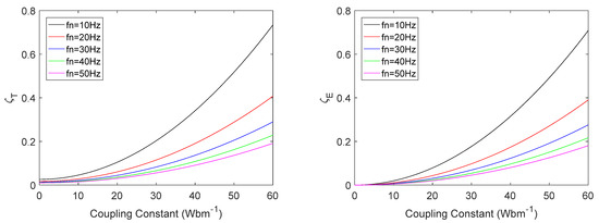
The variation of damping for several resonant frequencies from 10 Hz to 50 Hz is shown in Figure 2. The higher the resonant frequency, the lower the damping, but the coupling increases with an increased resonant frequency as in Equation (8).

Figure 2.
Comparison of the damping ratio with the coupling constant at different resonant frequencies for the total damping (left) and electromagnetic damping (right) when .
Based on a compromise between the degree of coupling and resonant frequency, there exists an optimum damping ratio at which the harvester performance becomes optimal, thereby maximizing the power harvested. The determination of the optimum damping ratio therefore becomes crucial because the power output would stagnate at a certain limit regardless of how high other electromagnetic parameters ( and ) become [12]. The approach adopted in this work is that using Equation (6), we plotted the damping ratio against the value of coupling until over a range of flux density, as shown in Figure 3. The figure shows the variation of the total damping ratio (left) with the coupling factor, and the variation of the electromagnetic damping ratio (right) with the coupling factor for the considered coil geometry having the following design parameters: mm; and load resistance .

Figure 3.
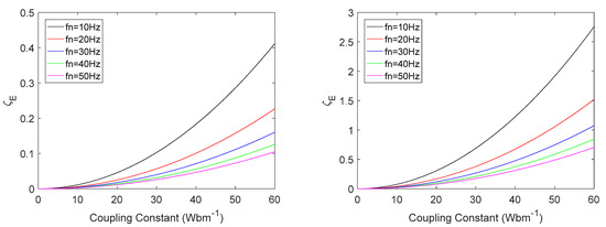
Comparison of the electromagnetic damping with the coupling constant at different resonant frequencies for different values of load resistance, (left) and (right).
The mechanical damping is reported as the sum of two independent damping components: material damping and thermoelastic damping [12,13,14,15]. The analysis shows that the mechanical damping ratio remains constant for any resonant frequency for all range of the flux density considered and the magnitude is likewise independent of the value of the load resistance as shown in Figure 3.
These damping terms were reported to be frequency dependent but has no dependency on the load resistance, thus explaining why the mechanical damping will not change with the load resistance. Since the mechanical damping remains constant and the same for each of the resonant frequency considered, the focus of further analysis will be on the variation of the coupling.
Figure 3 shows a comparison of the electromagnetic damping for different coupling factors using two values of load resistance, (left) and (right), at different resonant frequencies. The figure shows that the higher the load resistance, the lower is the damping ratio. In addition, the damping decreases as the resonant frequency increases. Intuitively we can then say that it is desirable to operate the harvester considered in this work in the frequency range above 20 Hz to avoid generating too large electromagnetic damping, in agreement with Equation (8).
We proceeded to investigate how the electromagnetic damping-coupling plot variation with the load resistance helps to determine the optimum window value for the coupling factor, damping ratio, and the flux density to produce a highly efficient (i.e., a maximized power output) harvester. Figure 3 shows that for any specific resonant frequency, as the applied load increases, the electromagnetic damping ratio reduces. This observation simultaneously confirms Equations (8) and (10), which affirms that the coupling factor has a direct relation with the electromagnetic damping ratio.
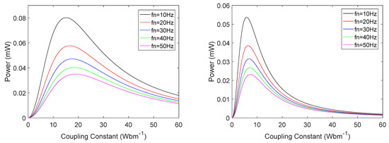
The power harvested in the coil winding was computed using Equation (9) as shown in Figure 4 for different resonant frequencies. Figure 4 shows a general observation that higher power could be harvested at lower resonant frequencies, however a much higher external load/sensor resistance value will be more beneficial since higher power is harvested with higher resistances. Figure 4 (right) is always higher than those with low resistance, Figure 4 (left), for the same resonances and lower electromagnetic damping values; this observation is justified by an inverse relation between the damping and load resistance as well as power harvested and load resistance as indicated in Equations (8) and (9). For the harvester design, there exists a value of load resistance called the optimum load resistance for which the harvested power becomes maximized and is not considered in this paper. Also of note is that there exists a point along the power-coupling factor curve where the harvested power becomes maximum for each specific resonant frequency. This maximized point is the location where the electromagnetic damping and the coupling factor becomes optimized, such that it will be a good decision to fabricate the harvester to have coupling and damping values around such optimums predicted in Figure 4. Since each maximized resonant power peak corresponds to an optimized resonant value of the flux density, the optimized flux density could be obtained using the optimum value of coupling ( and other coil parameters in Equation (6).

Figure 4.
Power harvested against the coupling constant at different resonant frequencies for different values of load resistance, (left) and (right).
5. Conclusions
The work herein investigated the interdependency among the vibration energy harvester’s coupling factor, the electromagnetic damping ratio, harvested power, the load resistance, and the resonant frequency. The analysis shows an inverse dependence of the damping ratio with the load resistance, thereby confirming Equation (8), while the harvested power as well as the coupling factor show direct dependence to load resistance. This suggests that for any resonant frequency, the harvested power harvested is maximized at a certain optimum value of the coupling factor and the damping ratio for each resonant. Using the known coil parameters and the optimum resonant coupling factor in Equation (6), we can then proceed to determine the optimum resonant flux density that will produce the maximum resonant power.
In summary, this work concluded that to ensure a higher harvested resonant power is available to the sensor node, the harvester must operate at certain resonant threshold value (20 Hz in the design considered) and that the harvester will only deliver maximum power at certain optimum load resistance. However, to ensure that an equivalent harvested resonant power is available to the sensor node in operation, during sensor fabrication, the optimum resistance of the sensors must hence match, i.e., be equal to the harvester optimum resistance, while their reactance are equals but opposite (impedance matching) to minimize the signal reflection while maximizing the power transferred of the sensor.
Supplementary Materials
The poster presentation is available online at https://www.mdpi.com/article/10.3390/ecsa-8-11279/s1.
Author Contributions
Conceptualization, T.I.T. and C.K.T.; methodology, T.I.T.; software, T.I.T.; validation, T.I.T., C.K.T. and D.H.; formal analysis, T.I.T.; investigation, C.K.T.; resources, C.K.T. and D.H.; data curation, C.K.T.; writing—original draft preparation, T.I.T.; writing—review and editing, C.K.T. and D.H.; visualization, C.K.T.; supervision, C.K.T. and D.H. All authors have read and agreed to the published version of the manuscript.
Funding
This research received no external funding.
Institutional Review Board Statement
Not applicable.
Informed Consent Statement
Not applicable.
Data Availability Statement
Not applicable.
Conflicts of Interest
The authors declare no conflict of interest.
References
- Richelli, A. EMI Susceptibility Issue in Analog Front-End for Sensor Applications. J. Sens. 2015, 2016, 1082454. [Google Scholar] [CrossRef][Green Version]
- Wang, J.Q.; Liu, Y.; Hou, M.Y.; Zhao, L.; Liu, T.Y. The Performance Analysis of Fiber Distributed Vibration Monitoring Technology Based on φ-OTDR. Appl. Mech. Mater. 2013, 336–338, 192–195. [Google Scholar] [CrossRef]
- Liu, J.-M. Photonic Devices; Cambridge University Press: Cambridge, UK, 2005. [Google Scholar] [CrossRef]
- Irfan, M.S.; Khan, T.; Hussain, T.; Liao, K.; Umer, R. Carbon coated piezoresistive fiber sensors: From process monitoring to structural health monitoring of composites—A review. Compos. Part A Appl. Sci. Manuf. 2021, 141, 106236. [Google Scholar] [CrossRef]
- Vagnoli, M.; Remenyte-Prescott, R.; Andrews, J. Railway bridge structural health monitoring and fault detection: State-of-the-art methods and future challenges. Struct. Health Monit. 2018, 17, 971–1007. [Google Scholar] [CrossRef]
- Prendergast, L.J.; Limongelli, M.P.; Ademovic, N.; Anžlin, A.; Gavin, K.; Zanini, M. Structural Health Monitoring for Performance Assessment of Bridges under Flooding and Seismic Actions. Struct. Eng. Int. 2018, 28, 296–307. [Google Scholar] [CrossRef]
- Capellari, G.; Chatzi, E.; Mariani, S. Cost–benefit optimization of structural health monitoring sensor networks. Sensors 2018, 18, 2174. [Google Scholar] [CrossRef] [PubMed]
- Ren, M.; Lu, P.; Chen, L.; Bao, X. Study of Φ-OTDR Stability for Dynamic Strain Measurement in Piezoelectric Vibration. Photonic Sens. 2016, 6, 199–208. [Google Scholar] [CrossRef]
- Park, G.; Rosing, T.; Todd, M.D.; Farrar, C.R.; Hodgkiss, W. Energy Harvesting for Structural Health Monitoring Sensor Networks. J. Infrastruct. Syst. 2008, 14, 64–79. [Google Scholar] [CrossRef]
- Cepnik, C.; Radler, O.; Rosenbaum, S.; Ströhla, T.; Wallrabe, U. Effective optimization of electromagnetic energy harvesters through direct computation of the electromagnetic coupling. Sens. Actuators A Phys. 2011, 167, 416–421. [Google Scholar] [CrossRef]
- Mösch, M.; Fischerauer, G. A comparison of methods to measure the coupling coefficient of electromagnetic vibration energy harvesters. Micromachines 2019, 10, 826. [Google Scholar] [CrossRef] [PubMed]
- Foong, F.M.; Thein, C.K.; Yurchenko, D. A two-stage electromagnetic coupling and structural optimisation for vibration energy harvesters. Smart Mater. Struct. 2020, 29, 085030. [Google Scholar] [CrossRef]
- Li, P.; Gao, S.; Niu, S.; Liu, H.; Cai, H. An analysis of the coupling effect for a hybrid piezoelectric and electromagnetic energy harvester. Smart Mater. Struct. 2014, 23, 65016. [Google Scholar] [CrossRef]
- Challa, V.R.; Cheng, S.; Arnold, D.P. The role of coupling strength in the performance of electrodynamic vibrational energy harvesters. Smart Mater. Struct. 2012, 22, 25005. [Google Scholar] [CrossRef]
- Foong, F.M.; Thein, C.K.; Yurchenko, D. Important considerations in optimising the structural aspect of a SDOF electromagnetic vibration energy harvester. J. Sound Vib. 2020, 482, 115470. [Google Scholar] [CrossRef]
Publisher’s Note: MDPI stays neutral with regard to jurisdictional claims in published maps and institutional affiliations. |
© 2021 by the authors. Licensee MDPI, Basel, Switzerland. This article is an open access article distributed under the terms and conditions of the Creative Commons Attribution (CC BY) license (https://creativecommons.org/licenses/by/4.0/).