Article

Bubble Formation in ITER-Grade Tungsten after Exposure to Stationary D/He Plasma and ELM-like Thermal Shocks

Forschungszentrum Jülich, Institut für Energie- und Klimaforschung, 52425 Jülich, Germany
*
Author to whom correspondence should be addressed.
J. Nucl. Eng. 2023, 4(1), 204-212; https://doi.org/10.3390/jne4010016
Submission received: 25 October 2022 / Revised: 27 January 2023 / Accepted: 13 February 2023 / Published: 21 February 2023

Abstract

:
Plasma-facing materials (PFMs) in the ITER divertor will be exposed to severe conditions, including exposure to transient heat loads from edge-localized modes (ELMs) and to plasma particles and neutrons. Tungsten is the material chosen as PFM for the ITER divertor. In previous tests, bubble formation in ITER-grade tungsten was detected when exposed to fusion relevant conditions. For this study, ITER-grade tungsten was exposed to simultaneous ELM-like transient heat loads and D/He (6%) plasma in the linear plasma device PSI-2. Bubble formation was then investigated via SEM micrographs and FIB cuts. It was found that for exposure to 100.000 laser pulses of 0.6 GWm−2 absorbed power density (Pabs), only small bubbles in the nanometer range were formed close to the surface. After increasing Pabs to 0.8 and 1.0 GWm−2, the size of the bubbles went up to about 1 µm in size and were deeper below the surface. Increasing the plasma fluence had an even larger effect, more than doubling bubble density and increasing bubble size to up to 2 µm in diameter. When using deuterium-only plasma, the samples showed no bubble formation and reduced cracking, showing such bubble formation is caused by exposure to helium plasma.

1. Introduction

Plasma-facing materials (PFMs) in the ITER divertor will be exposed to severe conditions. At full DT operation, these will include quasi-stationary and slow transient heat loads of 10–20 MWm−2 [1,2], as well as particle loads from plasma particles in the order of 1026 m−2 per pulse and 1030–1031 m−2 during the divertor lifetime [3]; and from neutrons released from the fusion reaction generating an estimated 0.5 displacements per atom (dpa) [4]. Additionally, transient thermal loads from instabilities such as edge-localized modes (ELMs) will affect PFMs with power densities of up to 1 GWm−2 in pulses of approximately 0.5 ms, with over 106 type I ELMs currently being expected to affect the ITER divertor during its lifetime.
Tungsten was selected as PFM for the ITER divertor in 2013 due to its favorable material properties, including a high melting point, high thermal conductivity, low tritium retention and low erosion rate (and other references) [5,6,7,8,9]. These make tungsten the most optimal candidate material for divertor PFMs. In spite of that, under such harsh conditions as in the ITER divertor, some challenges could still arise. One of the main issues in using tungsten as divertor material is its high atomic number (Z), which makes its cooling factor in the plasma core several times higher than for lower Z materials. Due to this fact, the maximum tolerable W concentration in the core plasma to allow for the burn conditions to be achievable is in the range of several 10−5 [10].
ELM-like thermal shocks have been shown to cause significant surface roughening, cracking, recrystallization, localized melting and material erosion [11,12,13,14,15,16]. When exposed simultaneously to thermal shocks and plasma loads some synergistic effects are observed, including worsened surface melting and cracking, embrittlement, as well as tungsten fuzz formation and bubble formation [17,18,19,20,21,22,23,24,25].
Helium nanobubbles have been observed when tungsten is exposed to helium plasma [23,25]. The formation of larges bubbles of up to 1 µm in tungsten when exposed to both, plasma and ELM-like heat loads, has been evidenced in similar experiments performed in the linear plasma generator PSI-2 [19,20], as well as in the linear divertor plasma simulator NAGDIS-II [26]. For the formation of such bubbles to occur, helium particles must have an energy of 6 eV or higher, corresponding to the surface barrier potential energy for helium particles to penetrate into tungsten. At the same time, the surface temperature of the material has to be higher than the recrystallization temperature, to facilitate the migration and coalescence of the bubbles [26]. Larger bubbles can considerably affect the material performance of tungsten PFMs, decreasing thermal conductivity, increasing tritium retention and accelerating material erosion and tungsten dust formation. This makes it vital to study the formation of these bubbles in order to understand the factors that affect their formation and growth, and how they can influence material properties and behavior under fusion-relevant conditions.

2. Experimental

In all tests, samples of ITER-grade tungsten provided by PLANSEE AG and characterized by having needle-like grains transversal to the surface were used. This microstructure is preferred for the ITER divertor due to its favorable cracking behavior when compared to other microstructures [14]. 5 mm thick samples with a geometry adapted for the PSI-2 holder (top surface of 10 mm × 10 mm, bottom surface of 10 mm × 12 mm and a 1 mm on two sides) were obtained by EDM cutting from a tungsten rod and then mechanically polished to a mirror finish with a mean arithmetic roughness of about 0.1 µm, using one different sample per treatment.
These samples were then exposed to ITER ELM-like loads in the linear plasma device PSI-2 at Forschungszentrum Jülich by simultaneously exposing them to stationary plasma and transient heat loads [27]. A deuterium plasma with 6% helium was generated by an arc discharge between a heated LaB6 cathode and a molybdenum anode. This gas mixture was chosen in order to simulate the expected plasma mixture in ITER and other future fusion reactors [28]. Plasma particles had an energy of approximately 35 eV and samples were exposed to a total plasma fluence of 3.6 × 1025 m−2 for the normal fluence tests and 5.9 × 1025 m−2 for the high fluence test (see Table 1).
A Nd:YAG laser with a wavelength of 1064 nm was used to generate the thermal shocks on the samples. 105 laser pulses were applied to each sample with a frequency of 10 Hz, a duration of 0.5 ms per pulse and with absorbed power densities (Pabs) of 0.6, 0.8 and 1.0 GWm−2. See Table 1 for a summary of all the treatments applied to the samples, including Pabs, heat flux factor (FHF), plasma flux, plasma fluence, gas mixture used and arithmetic average roughness (Ra).
A base temperature of 700 °C was used in all cases. This is higher than the ductile-brittle transition temperature (DBTT) of most tungsten materials and still several hundred degrees below its recrystallization temperature of 1100–1400 °C [29,30,31]. Exposing samples at a temperature above the DBTT of the material is of importance, as exposing cold tungsten to high heat flux loads will result in premature, brittle cracking [32].

3. Results and Discussion

SEM images of the laser-affected spot of all samples exposed to D/He (6%) (see Table 1) can be seen in Figure 1. Cracking behavior remains similar in all samples, despite the change in Pabs, with all samples showing extensive cracking and surface roughening. On sample B, exposed to 0.8 GWm−2, some areas inside the laser spot remained free of large cracks. However, samples A and C, tested with lower and higher Pabs respectively, showed more extensive cracking, leading to the conclusion that the initial conditions of the samples might have varied slightly (e.g., surface smoothness, microstructure and residual stresses), leading to a different cracking threshold. Another possibility is that experimental conditions, mainly plasma flux, could have had fluctuations during the experiment, leading to this cracking behavior.
It also might be that the lower surface temperature during the thermal shock events in sample A means that its behavior is less ductile than for sample B. At higher Pabs the energy deposited on the surface might then be so high that cracking occurs despite a higher ductility. Such behavior has been described previously on tungsten exposed to thermal shocks generated by an electron beam device [33].
Sample D, exposed to a higher plasma fluence, formed a crack network throughout the laser exposed area, in contrast to sample B. This shows either the effects of hydrogen/helium embrittlement, or the effect the formation of the bubbles have on the heat conductivity on the surface, which in turn lead to increased cracking of the material.
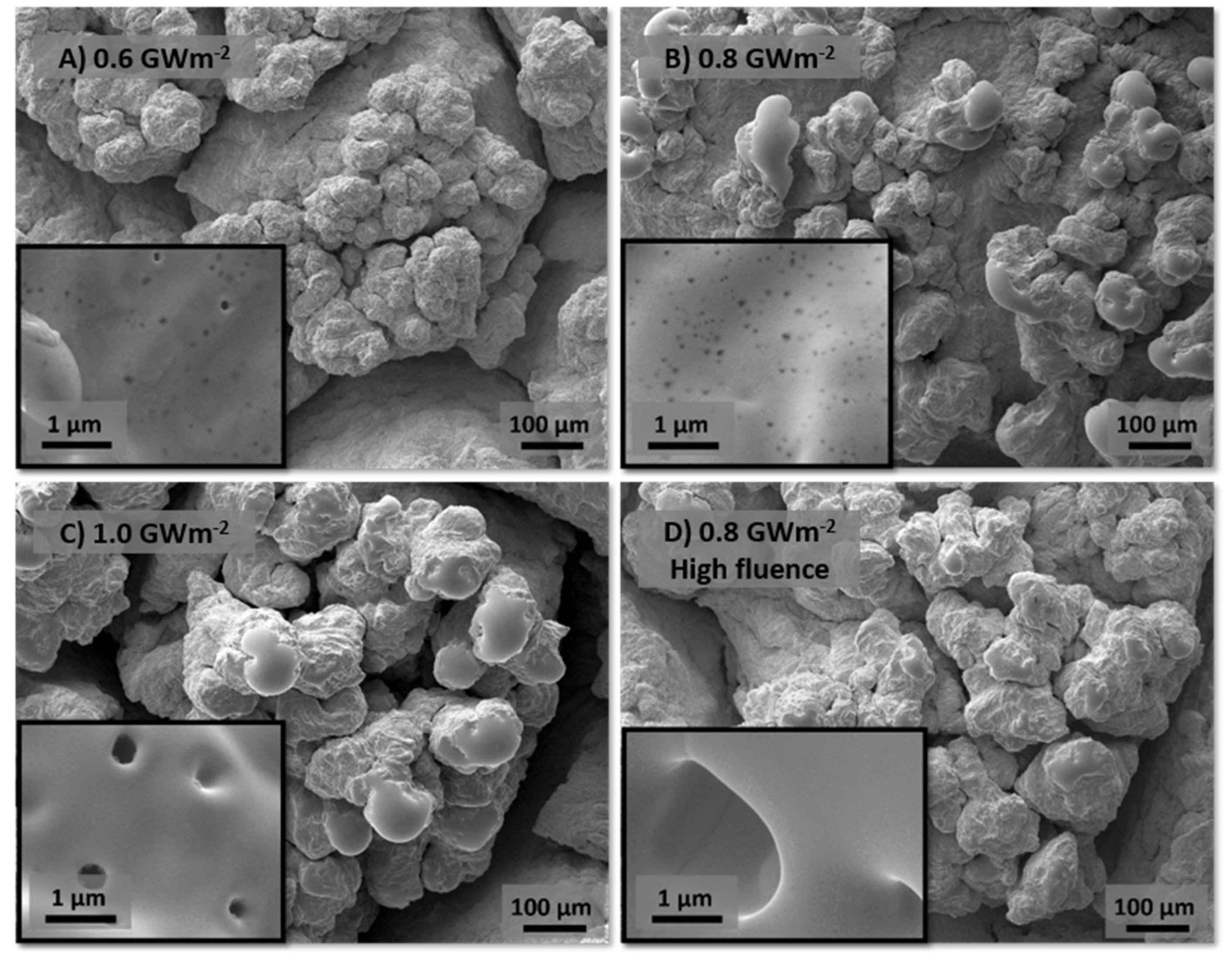
At higher magnifications (Figure 2), when exposed to 0.8 GWm−2 or higher Pabs, localized melting on the sample occurs, which produces the rounded, smooth structures that can be seen in the SEM images. The average surface temperature in the laser spot was measured with an infrared camera in samples exposed to the same conditions, and it was found that average temperature increased to 2200 °C during the 0.8 GWm−2 thermal shocks [19]. Such analyses, however, were not continued, as they cannot detect the large temperature variations along the laser spot surface, as evidenced by the melted areas. Such melting could pose an issue for the performance of a fusion reactor in that the ejection of melt droplets has been identified as one of the main mechanisms of material erosion [15]. The melting threshold for tungsten, between 0.6 and 0.8 GWm−2 also agrees with previous experiments [34], although this clearly depends on the initial conditions of the material, in particular base temperature.
The unmelted areas of the surface of the samples also clearly show the effects of bubble formation, as they are all pockmarked by pores from helium exposure. Samples A and B show nanometer-sized bubbles, while bubbles in sample C are in the range of a few hundreds of nanometers, showing a strong acceleration in bubble size increase after Pabs surpasses 0.8 GWm−2. Plasma fluence seems to have an even larger effect on bubble size, as sample D, exposed to higher fluence, showed the formation of micron-sized bubbles, even if it was exposed to a lower Pabs than sample C. If the ITER divertor reaches surface temperatures high enough to allow for the formation of helium bubbles, even larger bubbles might form, severely deteriorating the material properties, as a single full-power pulse in ITER is expected to cause a plasma fluence on the divertor of 1026 m−2 [3].
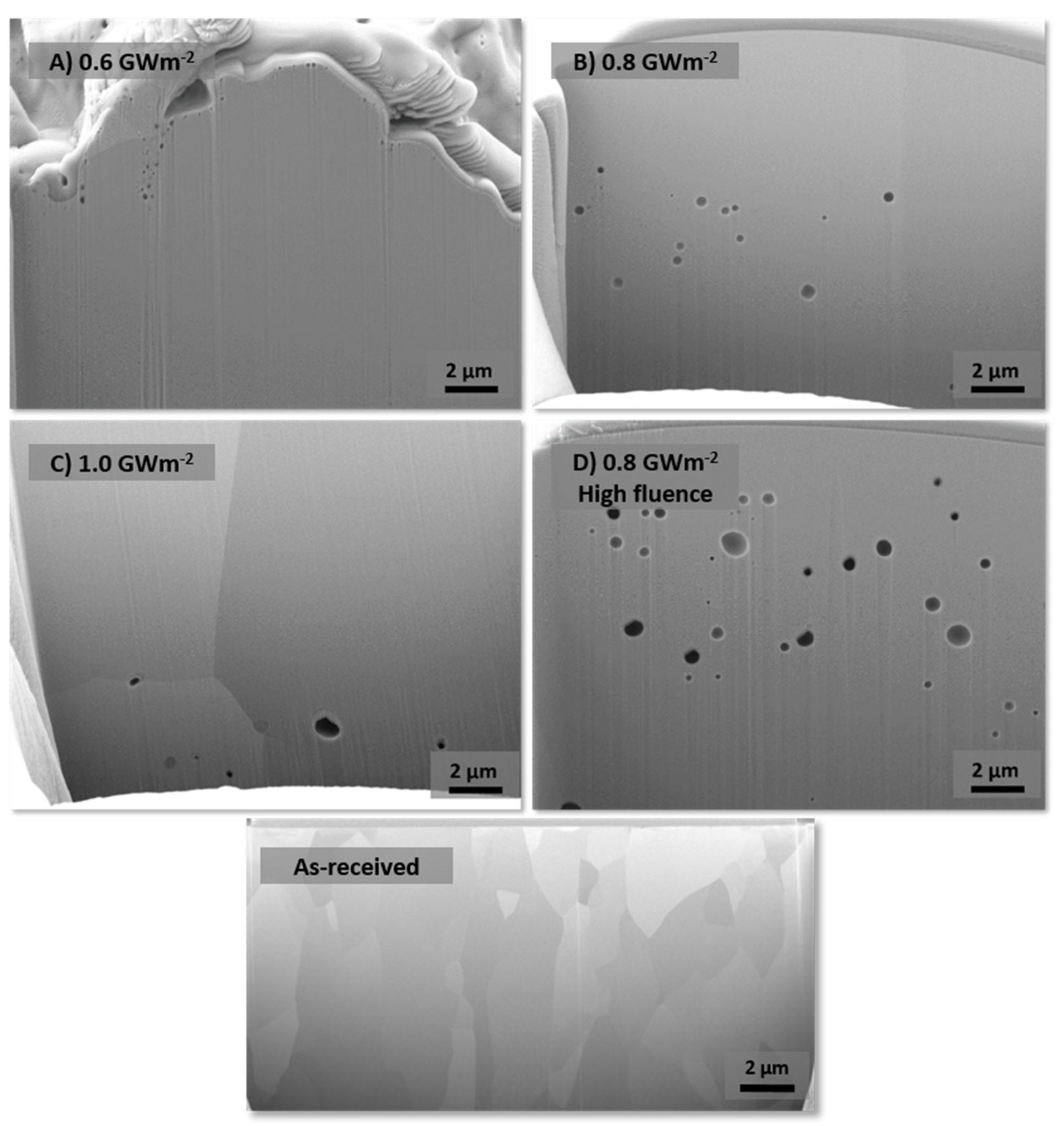
The FIB cuts in Figure 3 show how the as-received material shows no sign of bubble formation. After exposure, sample A indeed only formed bubbles near the surface. The surface temperature in sample A did not reach the temperature necessary for the diffusion and coalescence of helium bubbles. As temperature increases due to the higher energy deposited by the transient pulses, the tungsten bonds are weakened, and helium bubbles can more easily coalesce and migrate deeper into the material [26]. This is demonstrated in samples B, C and D, where bubbles are found as deep as the FIB cuts could be performed, about 15 µm. Formed bubbles are not only deeper in these samples than in sample A, they are also significantly larger, ranging from a few hundreds of nanometers in sample B to up to 1–2 µm in samples C and D.
The FIB cuts in samples B, C and D were performed on the cusps of one of the melt droplets, as these droplets are generally protruding upwards, a position that is favorable for performing FIB cuts. In such protruding areas of the material, its heat dissipation capability is degraded. Therefore, either melting or annealing, which has observed previously even at 1077 °C [35], could explain why no bubbles can be seen in the first few micrometers in samples B and C. However, as seen above in Figure 2, they do form in the surface. Nevertheless, the accelerated formation and growth when exposed to a higher fluence is again evident in sample D. Bubble density more than doubled from sample B to sample D. Bubbles occupied a 0.9% of the FIB cross-section area in sample B and 2% of the area for sample D.
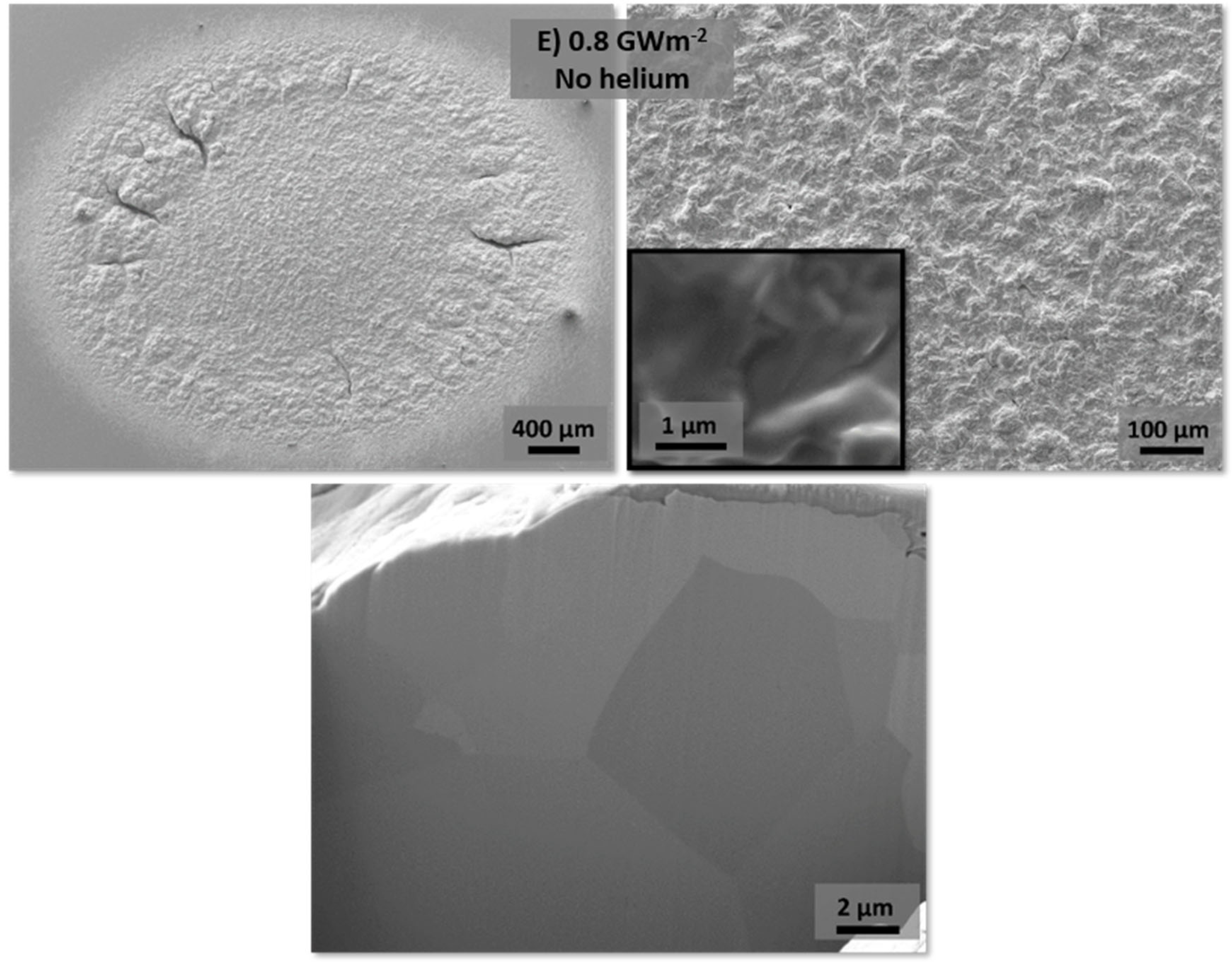
SEM images and a FIB cut of sample E, which was exposed to deuterium plasma, without helium, can be seen in Figure 4. In this case, the sample had only a few isolated cracks and the center of the laser spot remained without visible cracks. Neither melting nor bubble formation was observed in this case, and roughness (see Table 1) was much lower than for the other samples. This is, first of all, an indication that deuterium has no effect on bubble formation in tungsten, as has been observed also in tungsten exposed to only helium plasma [26,36]. And secondly, it shows that deuterium has a much lower synergistic effect on the deterioration of the material properties than helium does. The higher impact of helium on material properties could, at least partly, be caused by the bubble formation and their effect on the thermal conductivity and heat dissipation capacity of the material. This, in turn, leads to a larger temperature gradient between the laser spot and the surrounding material, causing higher stresses due to the expansion of the high-temperature material being restricted by the colder surrounding material [8] and a higher surface temperature in the laser affected area.

4. Conclusions

  • The objective of this work was to study the formation of bubbles in ITER-grade tungsten to understand the factors that cause it and influence their formation, as they could potentially have an effect on the performance of divertor PFCs in fusion reactors.
  • It was shown that at 700 °C base temperature, an exposure to transient heat loads of up to to 0.6 GWm−2 causes only nanometer-sized bubble on the surface of the material. Once Pabs is increased, the higher surface temperature allows bubbles to migrate and coalesce, causing the formation of larger bubbles deeper into the surface.
  • The effect of a higher plasma fluence was even larger. When plasma fluence was increased from 3.6 × 1025 m−2 to 5.9 × 1025 m−2 the bubble density and size grew, forming bubbles of up to 1–2 µm in diameter. Bubbles occupied a 0.9% of the FIB cross-section area in sample B and 2% of the area for sample D.
  • When exposing the samples to deuterium-only plasma, with no helium, no bubbles were formed. This means, thus, that bubble formation is caused exclusively by exposure to helium plasma. Furthermore, melting and cracking behavior were significantly worse in the samples exposed to combined D/He(6%) than in the one exposed to deuterium-only plasma. This evidences the loss in heat dissipation on the surface of the material and the degradation of material properties.
  • Alloys and other advanced concepts for plasma-facing materials for the divertor in future fusion reactors are being developed to solve some issues they are expected to face. Materials that are more resistant to neutron irradiation, cracking, recrystallization, oxidation in case of a loss-of-coolant accident (LOCA) and the improvement of the joint between PFM and cooling tube are being developed [37,38,39,40,41]. As of yet, no material has been developed specifically to solve the issue of bubble formation.
  • The effect that bubble formation could potentially have on the performance and lifetime of a fusion reactor such as ITER remains. To assess this issue, its influence on the thermal conductivity, hardness, erosion and deuterium retention of the material should be studied. Additionally, the bubble formation behavior of tungsten alloys and new PFM concepts should be studied.

Author Contributions

Conceptualization, M.G. and M.W.; methodology, M.G.; software, M.G. and A.K.; validation, M.G., and M.W.; formal analysis, M.G.; investigation, M.G.; resources, A.K., M.W. and B.U.; data curation, M.G.; writing—original draft preparation, M.G.; writing—review and editing, M.G. and M.W.; visualization, M.G.; supervision, M.W. and B.U.; project administration, M.W. and B.U.; funding acquisition, M.W. and B.U. All authors have read and agreed to the published version of the manuscript.

Funding

This work has been carried out within the framework of the EUROfusion Consortium, funded by the European Union via the Euratom Research and Training Programme (Grant Agreement No 101052200—EUROfusion). Views and opinions expressed are however those of the author(s) only and do not necessarily reflect those of the European Union or the European Commission. Neither the European Union nor the European Commission can be held responsible for them.

Data Availability Statement

The data presented in this study are available on request from the corresponding author.

Conflicts of Interest

The authors declare no conflict of interest.

References

  1. Hirai, T.; Escourbiac, F.; Carpentier-Chouchana, S.; Fedosov, A.; Ferrand, L.; Jokinen, T.; Komarov, V.; Kukushkin, A.; Merola, M.; Mitteau, R.; et al. ITER tungsten divertor design development and qualification program. Fusion Eng. Des. 2013, 88, 1798–1801. [Google Scholar] [CrossRef]
  2. Pitts, R.; Carpentier, S.; Escourbiac, F.; Hirai, T.; Komarov, V.; Kukushkin, A.; Lisgo, S.; Loarte, A.; Merola, M.; Mitteau, R.; et al. Physics basis and design of the ITER plasma-facing components. J. Nucl. Mater. 2011, 415, S957–S964. [Google Scholar] [CrossRef]
  3. De Temmerman, G.; Hirai, T.; Pitts, R.A. The influence of plasma-surface interaction on the performance of tungsten at the ITER divertor vertical targets. Plasma Phys. Control. Fusion 2018, 60, 44018. [Google Scholar] [CrossRef]
  4. Ueda, Y.; Schmid, K.; Balden, M.; Coenen, J.; Loewenhoff, T.; Ito, A.; Hasegawa, A.; Hardie, C.; Porton, M.; Gilbert, M. Baseline high heat flux and plasma facing materials for fusion. Nucl. Fusion 2017, 57, 92006. [Google Scholar] [CrossRef] [Green Version]
  5. Janeschitz, G. Plasma–wall interaction issues in ITER. J. Nucl. Mater. 2001, 290–293, 1–11. [Google Scholar] [CrossRef]
  6. Merola, M.; Escourbiac, F.; Raffray, A.R.; Chappuis, P.; Hirai, T.; Gicquel, S. Engineering challenges and development of the ITER Blanket System and Divertor. Fusion Eng. Des. 2015, 96–97, 34–41. [Google Scholar] [CrossRef]
  7. Philipps, V. Tungsten as material for plasma-facing components in fusion devices. J. Nucl. Mater. 2011, 415, S2–S9. [Google Scholar] [CrossRef]
  8. Linke, J.; Du, J.; Loewenhoff, T.; Pintsuk, G.; Spilker, B.; Steudel, I.; Wirtz, M. Challenges for plasma-facing components in nuclear fusion. Matter Radiat. Extrem. 2019, 4, 056201. [Google Scholar] [CrossRef] [Green Version]
  9. Merola, M.; Loesser, D.; Martin, A.; Chappuis, P.; Mitteau, R.; Komarov, V.; Pitts, R.; Gicquel, S.; Barabash, V.; Giancarli, L.; et al. ITER plasma-facing components. Fusion Eng. Des. 2010, 85, 2312–2322. [Google Scholar] [CrossRef]
  10. Pütterich, T.; Neu, R.; Dux, R.; Whiteford, A.; O’Mullane, M.; Summers, H.; the ASDEX Upgrade Team. Calculation and experimental test of the cooling factor of tungsten. Nucl. Fusion 2010, 50, 25012. [Google Scholar] [CrossRef] [Green Version]
  11. Loewenhoff, T.; Antusch, S.; Pintsuk, G.; Rieth, M.; Wirtz, M. High pulse number thermal shock testing of tungsten alloys produced by powder injection molding. Nucl. Mater. Energy 2019, 20, 100680. [Google Scholar] [CrossRef]
  12. Wirtz, M.; Linke, J.; Loewenhoff, T.; Pintsuk, G.; Uytdenhouwen, I. Thermal shock tests to qualify different tungsten grades as plasma facing material. Phys. Scr. 2016, T167, 14015. [Google Scholar] [CrossRef] [Green Version]
  13. Wirtz, M.; Cempura, G.; Linke, J.; Pintsuk, G.; Uytdenhouwen, I. Thermal shock response of deformed and recrystallised tungsten. Fusion Eng. Des. 2013, 88, 1768–1772. [Google Scholar] [CrossRef]
  14. Pintsuk, G.; Loewenhoff, T. Impact of microstructure on the plasma performance of industrial and high-end tungsten grades. J. Nucl. Mater. 2013, 438, S945–S948. [Google Scholar] [CrossRef]
  15. Bazylev, B.; Janeschitz, G.; Landman, I.; Pestchanyi, S.; Loarte, A.; Federici, G.; Merola, M.; Linke, J.; Zhitlukhin, A.; Podkovyrov, V.; et al. ITER transient consequences for material damage: Modelling versus experiments. Phys. Scr. 2007, T128, 229–233. [Google Scholar] [CrossRef]
  16. Klimov, N.; Podkovyrov, V.; Zhitlukhin, A.; Kovalenko, D.; Linke, J.; Pintsuk, G.; Landman, I.; Pestchanyi, S.; Bazylev, B.; Janeschitz, G.; et al. Experimental study of PFCs erosion and eroded material deposition under ITER-like transient loads at the plasma gun facility QSPA-T. J. Nucl. Mater. 2011, 415, S59–S64. [Google Scholar] [CrossRef]
  17. Morgan, T.W.; Balden, M.; Schwarz-Selinger, T.; Li, Y.; Loewenhoff, T.H.; Wirtz, M.; Brezinsek, S.; De Temmerman, G. ITER monoblock performance under lifetime loading conditions in Magnum-PSI. Phys. Scr. 2020, T171, 14065. [Google Scholar] [CrossRef]
  18. Morgan, T.; Li, Y.; Balden, M.; Brezinsek, S.; De Temmerman, G. Combined high fluence and high cycle number transient loading of ITER-like monoblocks in Magnum-PSI. Nucl. Fusion 2021, 61, 116045. [Google Scholar] [CrossRef]
  19. Gago, M.; Kreter, A.; Unterberg, B.; Wirtz, M. Synergistic effects of particle and transient heat loads on ITER-grade tungsten. Phys. Scr. 2020, T171, 14007. [Google Scholar] [CrossRef]
  20. Gago, M.; Kreter, A.; Unterberg, B.; Wirtz, M. Synergistic and separate effects of plasma and transient heat loads on the microstructure and physical properties of ITER-grade tungsten. Phys. Scr. 2021, 96, 124052. [Google Scholar] [CrossRef]
  21. Steudel, I.; Huber, A.; Kreter, A.; Linke, J.; Sergienko, G.; Unterberg, B.; Wirtz, M. Sequential and simultaneous thermal and particle exposure of tungsten. Phys. Scr. 2016, T167, 14053. [Google Scholar] [CrossRef]
  22. Wirtz, M.; Bardin, S.; Huber, A.; Kreter, A.; Linke, J.; Morgan, T.; Pintsuk, G.; Reinhart, M.; Sergienko, G.; Steudel, I.; et al. Impact of combined hydrogen plasma and transient heat loads on the performance of tungsten as plasma facing material. Nucl. Fusion 2015, 55, 123017. [Google Scholar] [CrossRef] [Green Version]
  23. Kajita, S.; Sakaguchi, W.; Ohno, N.; Yoshida, N.; Saeki, T. Formation process of tungsten nanostructure by the exposure to helium plasma under fusion relevant plasma conditions. Nucl. Fusion 2009, 49, 95005. [Google Scholar] [CrossRef]
  24. Kajita, S.; Kawaguchi, S.; Ohno, N.; Yoshida, N. Enhanced growth of large-scale nanostructures with metallic ion precipitation in helium plasmas. Sci. Rep. 2018, 8, 56. [Google Scholar] [CrossRef] [Green Version]
  25. Kong, F.; Qu, M.; Yan, S.; Zhang, A.; Peng, S.; Xue, J.; Wang, Y. Helium-induced hardening effect in polycrystalline tungsten. Nucl. Instrum. Methods Phys. Res. Sect. B: Beam Interact. Mater. At. 2017, 406, 643–647. [Google Scholar] [CrossRef]
  26. Nishijima, D.; Ye, M.; Ohno, N.; Takamura, S. Formation mechanism of bubbles and holes on tungsten surface with low-energy and high-flux helium plasma irradiation in NAGDIS-II. J. Nucl. Mater. 2004, 329–333, 1029–1033. [Google Scholar] [CrossRef]
  27. Kreter, A.; Brandt, C.; Huber, A.; Kraus, S.; Möller, S.; Reinhart, M.; Schweer, B.; Sergienko, G.; Unterberg, B. Linear Plasma Device PSI-2 for Plasma-Material Interaction Studies. Fusion Sci. Technol. 2015, 68, 8–14. [Google Scholar] [CrossRef]
  28. Reiter, D.; Wolf, G.H.; Kever, H. Burn condition, helium particle confinement and exhaust efficiency. Nucl. Fusion 1990, 30, 2141–2155. [Google Scholar] [CrossRef]
  29. Davis, J.; Barabash, V.; Makhankov, A.; Plöchl, L.; Slattery, K. Assessment of tungsten for use in the ITER plasma facing components. J. Nucl. Mater. 1998, 258–263, 308–312. [Google Scholar] [CrossRef]
  30. Panayotis, S.; Hirai, T.; Barabash, V.; Durocher, A.; Escourbiac, F.; Linke, J.; Loewenhoff, T.; Merola, M.; Pintsuk, G.; Uytdenhouwen, I.; et al. Self-castellation of tungsten monoblock under high heat flux loading and impact of material properties. Nucl. Mater. Energy 2016, 12, 200–204. [Google Scholar] [CrossRef]
  31. Zhang, X.-X.; Yan, Q.-Z.; Yang, C.-T.; Wang, T.-N.; Xia, M.; Ge, C.-C. Recrystallization temperature of tungsten with different deformation degrees. Rare Met. 2014, 35, 566–570. [Google Scholar] [CrossRef]
  32. Gunn, J.; Bucalossi, J.; Corre, Y.; Diez, M.; Delmas, E.; Fedorczak, N.; Grosjean, A.; Firdaouss, M.; Gaspar, J.; Loarer, T.; et al. Thermal loads in gaps between ITER divertor monoblocks: First lessons learnt from WEST. Nucl. Mater. Energy 2021, 27, 100920. [Google Scholar] [CrossRef]
  33. Loewenhoff, T.; Linke, J.; Pintsuk, G.; Thomser, C. Tungsten and CFC degradation under combined high cycle transient and steady state heat loads. Fusion Eng. Des. 2012, 87, 1201–1205. [Google Scholar] [CrossRef]
  34. Bazylev, B.; Janeschitz, G.; Landman, I.; Pestchanyi, S.; Loarte, A.; Federici, G.; Merola, M.; Linke, J.; Hirai, T.; Zhitlukhin, A.; et al. Behaviour of melted tungsten plasma facing components under ITER-like transient heat loads. Fusion Eng. Des. 2008, 83, 1077–1081. [Google Scholar] [CrossRef]
  35. Ialovega, M.; Bernard, E.; Barthe, M.-F.; Bisson, R.; Campos, A.; Cabié, M.; Neisius, T.; Sakamoto, R.; Kreter, A.; Grisolia, C.; et al. Helium-induced morphology evolution in tungsten under thermal treatment. Nucl. Fusion 2022, 62, 126022. [Google Scholar] [CrossRef]
  36. Wirtz, M.; Berger, M.; Huber, A.; Kreter, A.; Linke, J.; Pintsuk, G.; Rasinski, M.; Sergienko, G.; Unterberg, B. Influence of helium induced nanostructures on the thermal shock performance of tungsten. Nucl. Mater. Energy 2016, 9, 177–180. [Google Scholar] [CrossRef] [Green Version]
  37. Terentyev, D.; Jenus, P.; Broco, E.S.; Zinovev, A.; Chang, C.; Garcia-Rosales, C.; Kocen, M.; Novak, S.; Van Renterghem, W. Development of irradiation tolerant tungsten alloys for high temperature nuclear applications. Nucl. Fusion 2022, 62, 86035. [Google Scholar] [CrossRef]
  38. Coenen, J.W. Fusion Materials Development at Forschungszentrum Jülich. Adv. Eng. Mater. 2020, 22, 1901376. [Google Scholar] [CrossRef] [Green Version]
  39. Linsmeier, C.; Rieth, M.; Aktaa, J.; Chikada, T.; Hoffmann, A.; Houben, A.; Kurishita, H.; Jin, X.; Li, M.; Litnovsky, A.; et al. Development of advanced high heat flux and plasma-facing materials. Nucl. Fusion 2017, 57, 92007. [Google Scholar] [CrossRef]
  40. Litnovsky, A.; Wegener, T.; Klein, F.; Linsmeier, C.; Rasinski, M.; Kreter, A.; Unterberg, B.; Coenen, J.; Du, H.; Mayer, J.; et al. Smart tungsten alloys as a material for the first wall of a future fusion power plant. Nucl. Fusion 2017, 57, 66020. [Google Scholar] [CrossRef]
  41. Litnovsky, A.; Wegener, T.; Klein, F.; Linsmeier, C.; Rasinski, M.; Kreter, A.; Tan, X.; Schmitz, J.; Mao, Y.; Coenen, J.W.; et al. Advanced smart tungsten alloys for a future fusion power plant. Plasma Phys. Control. Fusion 2017, 59, 64003. [Google Scholar] [CrossRef]
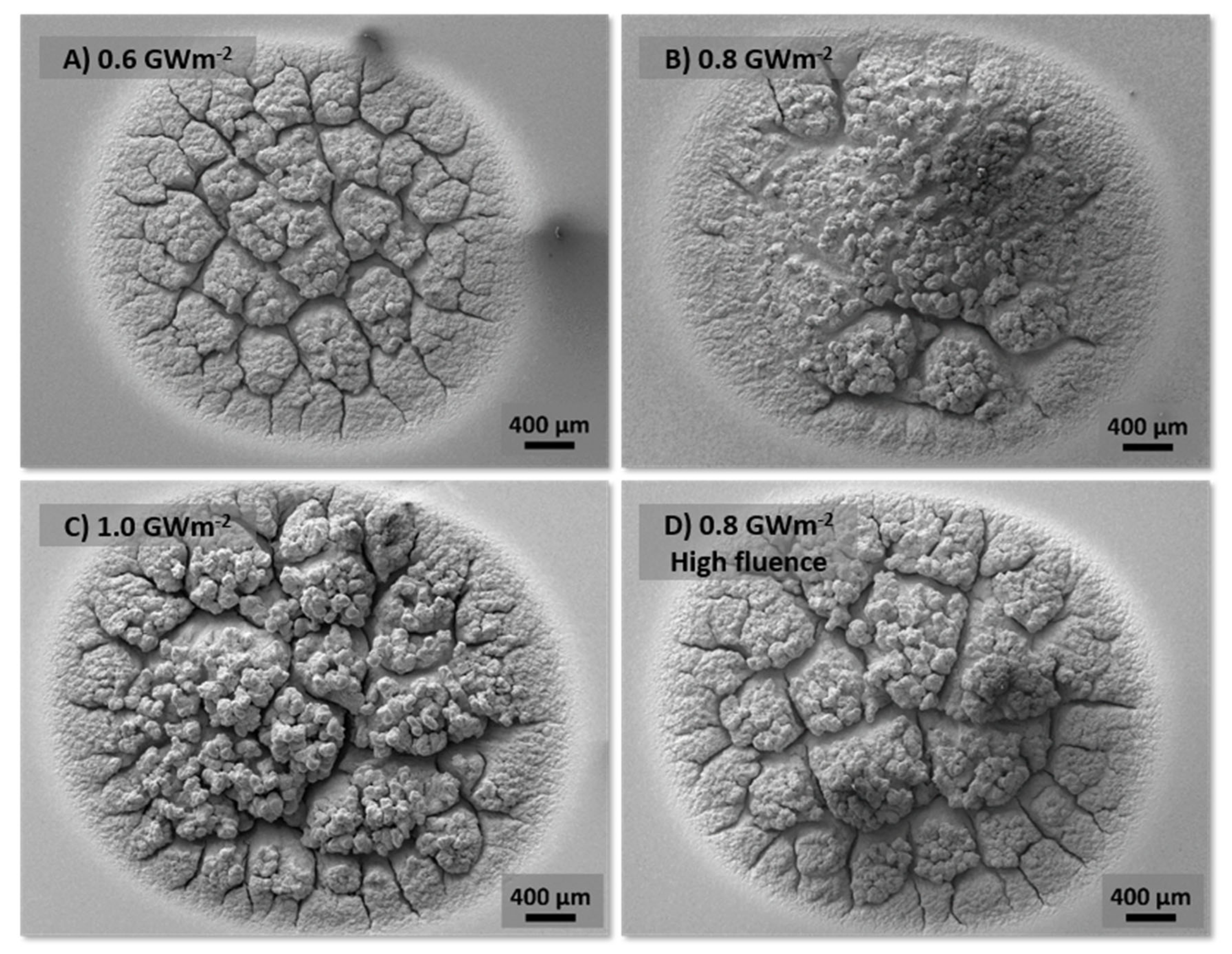
Figure 1. SEM micrographs of the whole laser-affected spot of all samples exposed to D/He(6%) plasma. Samples were simultaneously exposed to 105 laser pulses with a Pabs of (A) 0.6 GWm−2, (B) 0.8 GWm−2, (C) 1.0 GWm−2 and (D) 0.8 GWm−2. Sample D was exposed to a higher plasma fluence than samples A, B and C.
Jne 04 00016 g001
Figure 2. Close-up of the laser-affected area of all samples exposed to D/He (6%) plasma. Samples were simultaneously exposed to 105 laser pulses with a Pabs of (A) 0.6 GWm−2, (B) 0.8 GWm−2, (C) 1.0 GWm−2 and (D) 0.8 GWm−2. Sample D was exposed to a higher plasma fluence than samples A, B and C.
Jne 04 00016 g002
Figure 3. FIB cuts of the laser-affected area of all samples exposed to D/He(6%) plasma. Samples were simultaneously exposed to 105 laser pulses with a Pabs of (A) 0.6 GWm−2, (B) 0.8 GWm−2, (C) 1.0 GWm−2, (D) 0.8 GWm−2 and of an as-received sample. Sample D was exposed to a higher plasma fluence than samples A, B and C.
Jne 04 00016 g003
Figure 4. SEM images of the laser spot, close-up and FIB cut of sample E, which was exposed to 105 laser pulses with a Pabs of 0.8 GWm−2 and D plasma.
Jne 04 00016 g004
Table 1. Summary of the plasma and thermal shock treatments applied to ITER-grade tungsten samples and the resulting average arithmetic roughness (Ra) of the surface.
SampleABCDE
Pabs (GWm−2)0.60.81.00.80.8
FHF (MWs−1/2)1318221818
Flux (m−2s−1)3.2 × 10213.2 × 10213.2 × 10215.5 × 10213.2 × 1021
Fluence (m−2)3.6 × 10253.6 × 10253.6 × 10255.9 × 10253.6 × 1025
GasD/He (6%)D/He (6%)D/He (6%)D/He (6%)D
Ra (µm)25.749.533.547.32.27
Disclaimer/Publisher’s Note: The statements, opinions and data contained in all publications are solely those of the individual author(s) and contributor(s) and not of MDPI and/or the editor(s). MDPI and/or the editor(s) disclaim responsibility for any injury to people or property resulting from any ideas, methods, instructions or products referred to in the content.