You are currently viewing a new version of our website. To view the old version click .
Hydrogen
  • Article
  • Open Access

13 October 2025

Design and Optimization of a Solar Parabolic Dish for Steam Generation in a Blue Hydrogen Production Plant

,
,
,
,
,
,
,
and
1
Mechanical and Energy Engineering Department, Imam Abdulrahman Bin Faisal University, Dammam 31441, Saudi Arabia
2
Global Health, Education and Policy Alliance GHEPA, c/o Calliopée Sàrl, Rue de Chantepoulet 10, 1201 Genève, Switzerland
*
Author to whom correspondence should be addressed.
Hydrogen2025, 6(4), 85;https://doi.org/10.3390/hydrogen6040085 
(registering DOI)

Abstract

The integration of renewable energy into industrial processes is crucial for reducing the carbon footprint of conventional hydrogen production. This work presents detailed design, optical–thermal simulation, and performance analysis of a solar parabolic dish (SPD) system for supplying high-temperature steam to a Steam Methane Reforming (SMR) plant. A 5 m diameter dish with a focal length of 3 m was designed and optimized using COMSOL Multiphysics (version 6.2) and MATLAB (version R2023a). Optical ray tracing confirmed a geometric concentration ratio of 896×, effectively focusing solar irradiation onto a helical cavity receiver. Thermal–fluid simulations demonstrated the system’s capability to superheat steam to 551 °C at a mass flow rate of 0.0051 kg/s, effectively meeting the stringent thermal requirements for SMR. The optimized SPD system, with a 5 m dish diameter and 3 m focal length, was designed to supply 10% of the total process heat (≈180 GJ/day). This contribution reduces natural gas consumption and leads to annual fuel savings of approximately 141,000 SAR (Saudi Riyal), along with a substantial reduction in CO2 emissions. These quantitative results confirm the SPD as both a technically reliable and economically attractive solution for sustainable blue hydrogen production.

1. Introduction

Concentrated Solar Power (CSP) is a widely adopted form of renewable energy with diverse applications in power generation and thermal processes. A global review by Alami et al. [] reported the existence of 114 operational CSP projects as of 2023, reflecting the growing interest in solar thermal technologies. CSP systems include various technologies such as parabolic troughs, linear Fresnel reflectors, solar collectors, lenses, and solar parabolic dishes (SPD) [,,]. Among these, SPDs are considered the most efficient due to their high concentration capability and ability to reach elevated temperatures [,,]. SPD systems function by focusing incident solar rays onto a single point known as the focal point. This concentration results in a significant thermal intensity at the receiver, which can be used to heat working fluids [,,]. The performance and effectiveness of an SPD are influenced by two main categories of parameters: geometrical and optical [,]. Geometrical parameters include the dish diameter, depth, aspect ratio, aperture area, focal length, and the geometrical concentration ratio (GCR). These parameters define the shape and focusing ability of the dish. Optical parameters, on the other hand, determine the efficiency of solar energy concentration and include reflectivity, transmissivity, absorptivity, emissivity, direct normal irradiance (DNI), and optical efficiency []. The choice of reflective materials significantly impacts the SPD’s optical performance. A comparative study by Korwan [] evaluated various coatings, including aluminum polymer, silver polymer, and gold polymer films. The results demonstrated that aluminum polymer film exhibited superior performance in terms of power output, thermal efficiency, and useful energy delivery. Further optical performance analysis was conducted by Pavlovic et al. [], who modeled an SPD with a 3.8 m diameter under a DNI of 800 W/m2. The study highlighted the importance of focal length optimization to maximize thermal energy capture. The receiver, positioned at the focal point, is responsible for absorbing and transferring this concentrated heat to a working fluid. SPD systems often use solar receivers, which typically consist of a housing and tubular coil structures to contain and heat the fluid [,,]. Among the various receiver configurations, cavity receivers particularly cylindrical cavity designs are most commonly used due to their high thermal efficiency. Bellos et al. [] compared multiple cavity geometries and found cylindrical receivers to be among the most efficient designs tested. The performance of these receivers depends on several interrelated factors, including thermal properties, fluid dynamics, and optical characteristics []. Material selection for receiver tubes is also critical. Wang et al. [] evaluated thermal stresses on copper, aluminum, and stainless-steel tubes under concentrated solar irradiation. The study concluded that copper, with a thermal stress of 5 MPa, is the most suitable material due to its low thermal expansion and high conductivity. Working fluids such as air, molten salt, liquid sodium, and water influence both the design and thermal performance of the receiver system [,]. Key geometrical design factors like tube length, diameter, coil pitch, number of turns, and helical radius are directly affected by the fluid properties and target operating conditions. To optimize fluid flow in helically coiled tubes, Sigalloti et al. [] emphasized the importance of analyzing parameters such as the Reynolds number, Dean number, and curvature ratio. The Dean number, a function of both the Reynolds number and curvature ratio (tube radius to helical radius), plays a vital role in characterizing secondary flows that enhance heat transfer in turbulent regimes. Water is a particularly valuable working fluid due to its ability to generate steam at high temperatures, making it suitable for processes such as Steam Methane Reforming (SMR). SPD systems can heat water to temperatures up to 600 °C, which are adequate for initiating SMR reactions []. Finally, the integration of SPD with hydrogen production has been explored by Avargani et al. [], who proposed a solar-driven propane steam reformer. Their parametric analysis demonstrated that the SPD system could support conversion processes at inlet pressures of 50 MPa and temperatures starting from 426.85 °C. These findings support the viability of using SPD systems in SMR applications, particularly in sustainable hydrogen production. It should be noted that this SPD system is a component of a larger, integrated blue hydrogen production process. The associated reforming and capture units are discussed in our companion studies, while the present work focuses exclusively on the design and analysis of the renewable thermal energy input system. While previous studies have analyzed SPD systems for general applications, no prior work has focused on their direct integration into SMR for blue hydrogen production. This study specifically addresses this gap. This study therefore aims to bridge this gap by specifically designing, modeling, and evaluating a solar parabolic dish (SPD) system to demonstrate its viability as a direct source of industrial process heat. The intended outcomes of this research are to (1) develop an optically and thermally optimized SPD design capable of delivering superheated steam at temperatures exceeding 500 °C; (2) quantify its specific contribution to the energy balance of an SMR plant, targeting a 10% displacement of the natural gas-derived heat load; and (3) conduct a rigorous techno-economic analysis to validate the economic and environmental merits of this solar-integration strategy, ultimately providing a replicable model for decarbonizing high-temperature industrial processes.

2. Geometrical Modelling

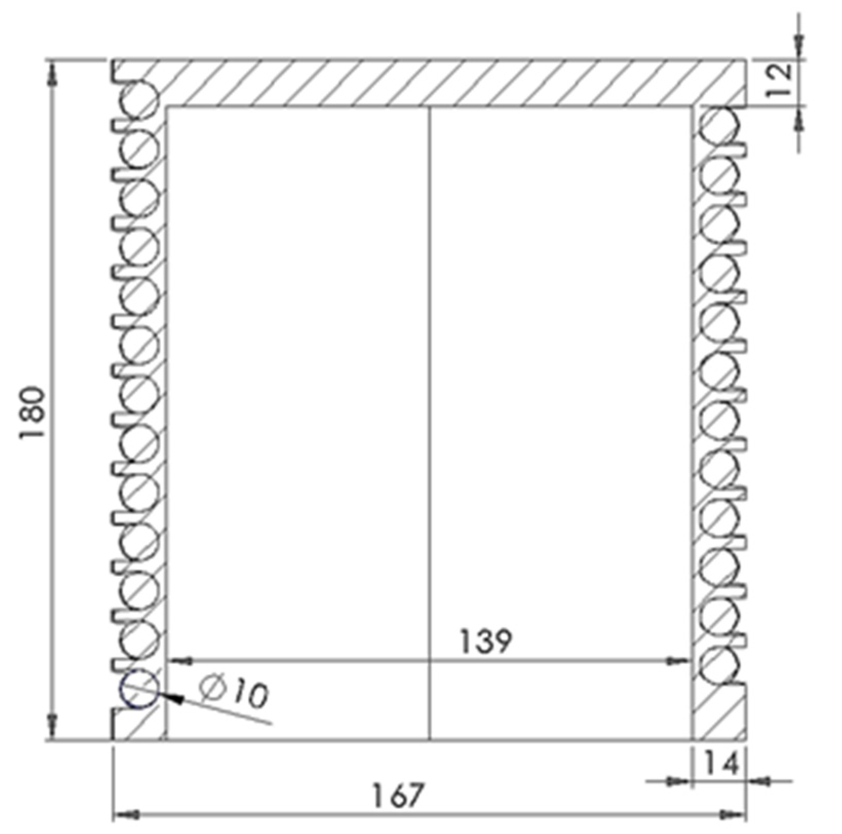
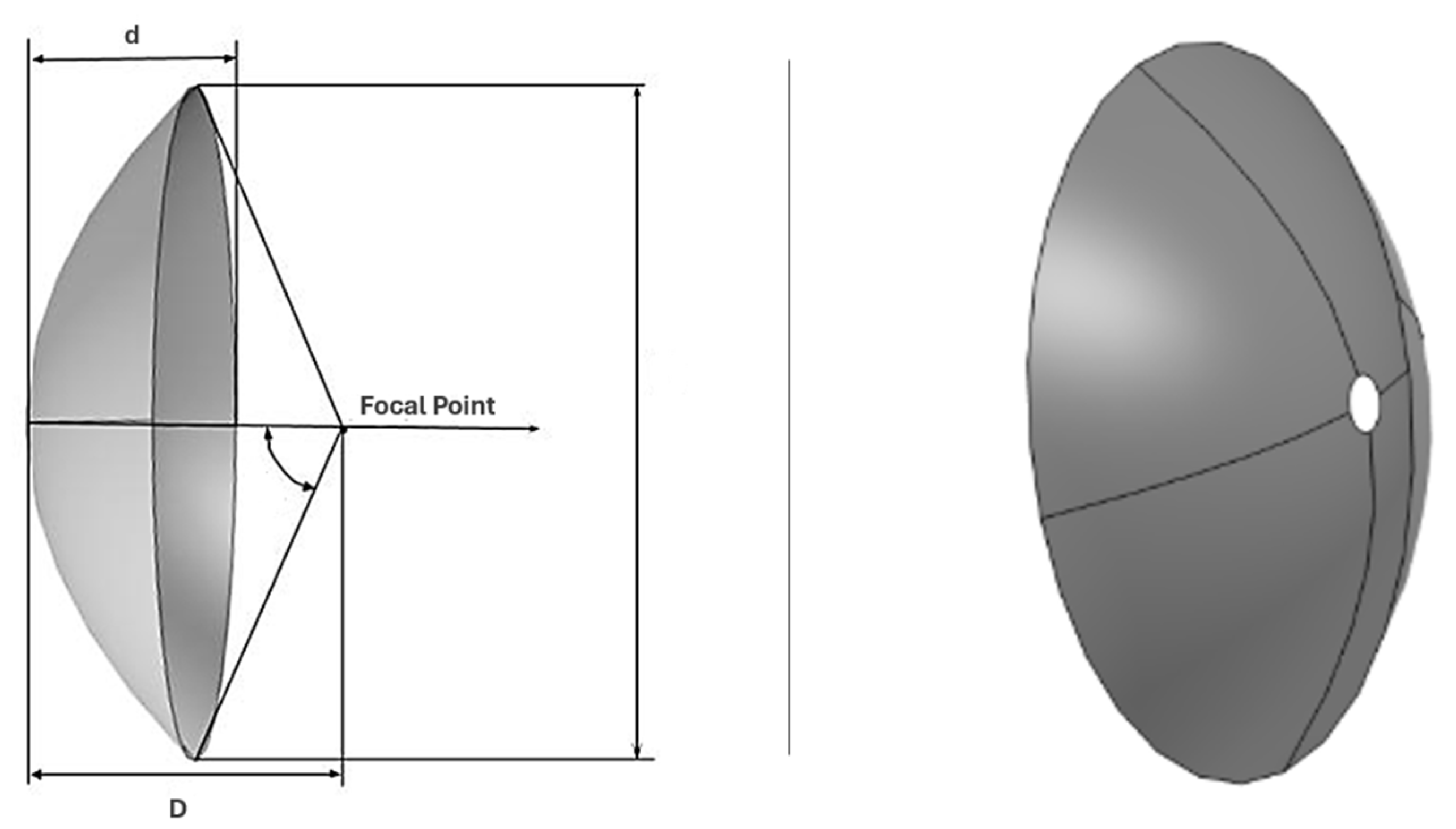
The incorporation of SPD into the SMR process instead of using a boiler like the industry standard plays a pivotal role in enhancing sustainability and minimizing greenhouse gas (GHG) emissions. Figure 1 and Figure 2 illustrate the geometrical dimensions of the SPD and the thermal receiver. The dish’s performance and thermal efficiency are strongly influenced by several geometric and optical parameters such as the focal length, dish diameter, cavity diameter, rim angle, reflectivity, emissivity, transmissivity, absorptivity, and direct normal irradiance. These parameters were optimized to ensure maximum solar energy concentration at the focal point where the receiver is positioned. Optimizing these specifications allows the system to achieve the high temperatures necessary for Steam Methane Reforming (SMR), specifically preheating steam to 500 °C.
Figure 1. SPD design and dimension.
Figure 2. Receiver cavity dimension.
The geometry of the parabolic dish is defined mathematically to ensure efficient solar energy concentration:
x 2 + y 2 = 4 f z
Equation (2) represents the standard paraboloid geometry, where f is the focal length. It ensures that all reflected rays converge at the focus, maximizing solar radiation capture. The dish depth d is related to the diameter D and focal length f by:
d = D 2 16 f
A deeper dish enhances concentration efficiency but may require more precise solar tracking, highlighting a design trade-off between performance and system complexity. The focal length f depends on the dish diameter (D) and rim angle (ψrim) [].
f = D 4 t a n ψ rim   2
In our case, a rim angle of 45° provided an optimal balance between focal length and receiver placement for efficient boundary heating. The surface area S of the dish, critical for determining the solar collection potential, is calculated as:
S = 8 π 3 f 2 1 + D 4 f 2 3 2 1
The aperture area Acon, through which sunlight enters, is given by:
A con .   = π 4 D 2
The receiver diameter depends on the focal length (f), angular acceptance (θa), and incidence angle (ψm). A smaller receiver diameter reduces heat loss but requires precise alignment with the concentrated rays [].
D rec .   = f tan θ a c o s ψ m ( 1 + c o s ψ m )
This small ψm reflects the theoretical alignment; practical deviations are included in the surface slope error parameter. The receiver aperture area determines the amount of concentrated solar radiation absorbed. This must balance with the dish’s aperture area to avoid under-utilization or excessive heat loss.
A rec = π 4 D rec .   2
To enhance thermal transfer, the receiver is designed as a helical coil, which increases fluid contact time and promotes secondary flow, improving heat transfer performance. The relevant helical parameters include the curvature ratio (γ) and dimensionless pitch (β):
γ = R R c
β = h 2 π R c
Based on findings from Pavlovic et al. [] and Wang et al. [], the focal length of 3 m and the use of copper as a receiver material were selected to optimize solar concentration and thermal conductivity in the model.
Table 1 shows the parameters of the SPD system. These parameters are critical for the system’s performance, as they determine the ability to achieve a high boundary heat source capable of reaching the temperatures required for the SMR reaction. Increasing the dish depth enhances concentration efficiency but necessitates more precise tracking systems, while reducing the receiver diameter minimizes heat losses but requires higher optical precision. Following Pavlovic et al. [] and Bellos et al. [], the 5 m dish diameter and 3 m focal length were chosen to balance high concentration with manageable tracking requirements. Furthermore, the choice of receiver size and coil pitch was made to balance heat transfer enhancement against pumping power, as noted in prior studies [].
Table 1. Geometrical parameters of solar parabolic dish [,,].

Optimization Strategy for SMR Integration

The selected 5 m dish diameter and 3 m focal length were determined from ASPEN Plus process modeling of the SMR unit. The SPD was sized to displace 10% of the HEAT-H2O unit load. Receiver coil dimensions were chosen to achieve superheated steam at 551 °C while minimizing pumping losses.

3. Optical Analysis

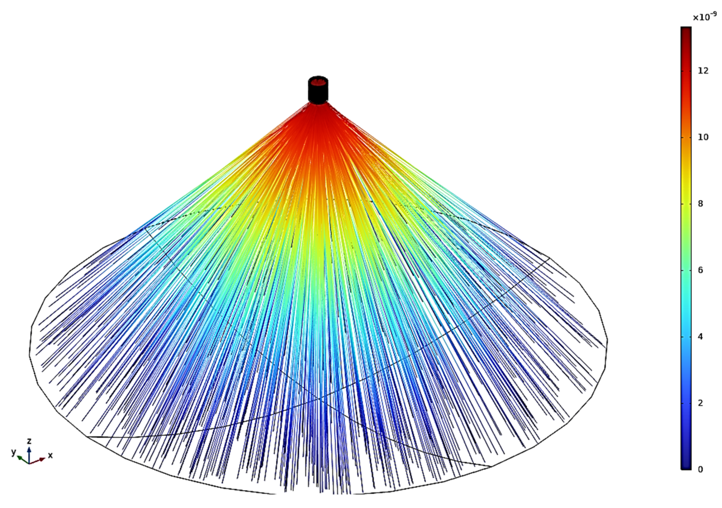
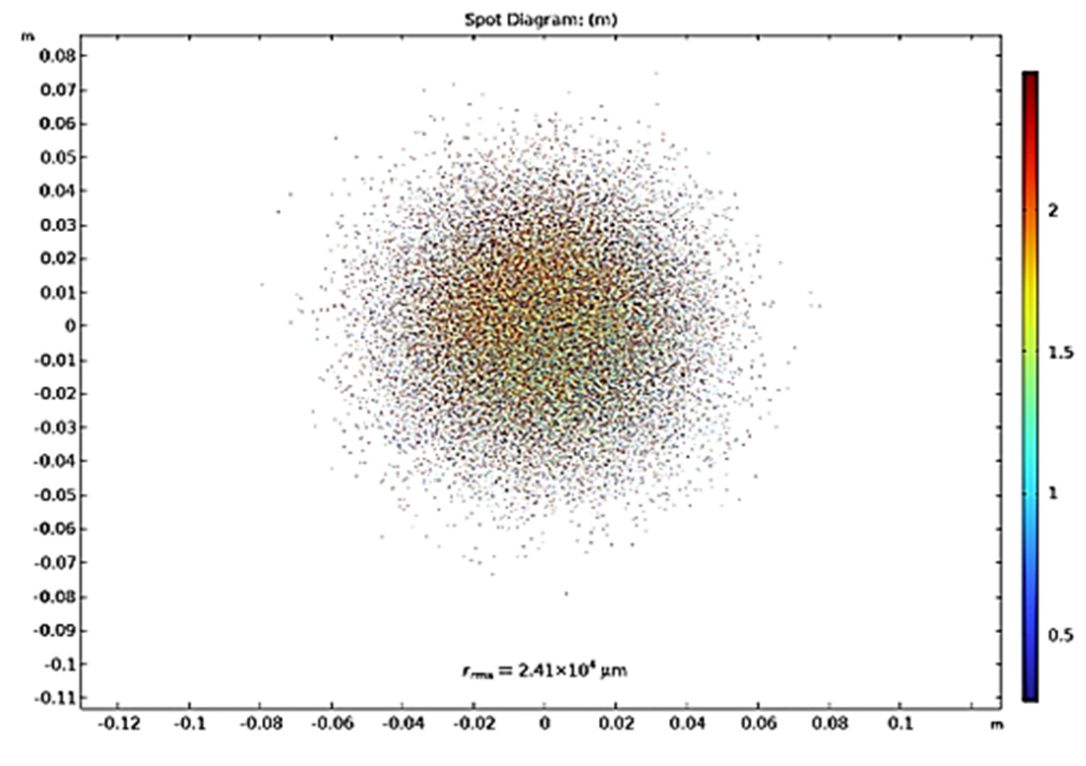
Proper alignment of the receiver at the dish’s focal point, as determined by Equation (10), is critical for maximizing thermal efficiency. Continuous monitoring is necessary to maintain optimal alignment under varying solar angles. Figure 3 illustrates the ray tracing results, showing effective concentration toward the receiver, while Figure 4 presents the spot diagram, confirming the focal sharpness and accuracy.
Figure 3. Optical ray trajectories.
Figure 4. Spot diagram at focal point.
The focal spot pattern in Figure 4 was validated by comparing with Pavlovic et al. [], showing similar focal sharpness and confirming the adequacy of 10,000 rays resolution.
The Geometrical Concentration Ratio (GC) quantifies the focusing capability:
G C = sin 2 θ a 1 = A a A r
To ensure accurate and reliable simulation results, it is essential to define the correct optical conditions. Direct Normal Irradiance (DNI) represents the intensity of solar radiation received per unit area, perpendicular to the sun’s rays, and is typically at its peak (~1000 W/m2) around 12:00 P.M. The number of rays (N), set to 10,000 in this study (see Table 2), which defines the resolution and precision of the optical simulation, as visualized in Figure 3 and Figure 4. The Geometrical Concentration Ratio (GC), calculated using Equation (10), quantifies how effectively the parabolic dish focuses solar radiation. It is defined as the ratio between the aperture area (Aa) and the receiver area (Ar). A higher GC indicates a greater ability to concentrate sunlight onto a small area. Finally, the surface slope error (σ) measured at (0.00175 rad) describes the deviation in the mirror surface alignment from the ideal shape, while in real mirrors slope errors are typically 0.002–0.01 rad. This parameter influences the beam’s angular spread and thus the sharpness of focus at the receiver.
Table 2. Optical parameters.

4. Thermal Analysis for Cavity Receiver

This section evaluates the heat transfer and fluid dynamics inside the helical pipe receiver, which are critical for achieving the required outlet temperatures. The Dean number De, combining Reynolds number Re and curvature ratio γ, characterizes secondary flow effects:
D e = γ R e
The friction factor F represents energy loss due to pipe wall interactions:
      F = R ρ v 2 d p d s
Bulk velocity (v) is derived as:
v = Q π R 2
The dimensionless volumetric flow rate Q helps characterize pressure-driven flow:
Q = 1 R 2 ρ ( d p / d s ) R 1 / 2 Q  
Heat transfer within the receiver involves conduction, radiation, and convection.
Fourier’s Law of heat conduction:
q = k Δ T  
Radiative heat loss:
q = ε σ T a m b 4 T 4  
Convective heat loss:
      q = h T e x t T
Conduction heat Loss:
Q conduction   = k A support   L T surface   T ambient  
Useful Heat Gain:
Q useful   = m ˙ c p T outlet   T inlet  
Receiver Efficiency:
η receiver   = Q useful Q absorbed
The boundary heat source, which represents the effective thermal input to the receiver, is:
Q b = A r D N I   η o p t , d C R
Here η o p t , d , and CR denotes the product of optical efficiency and geometric concentration ratio. Thermal property relationships:
Prandtl number:
P r = c p μ k
Nusselt number (forced convection correlation):
N u = 0.332 R e 1 2   P r 1 3
The heat transfer coefficient:
      h = k   N u D
Table 3 shows the water entering the system at 23 °C and is heated to 551 °C, with an inlet specific heat capacity of 4.18 kJ/kg·K and a mass flow rate of 0.005134 kg/s. The flow is characterized by a Reynolds number of 701.8 and a Dean number of 179.41. Confirming a transitional-to-turbulent regime suitable for enhanced heat transfer. A Prandtl number of 6.44 and a Nusselt number of 22.8 yield a convective heat transfer coefficient of 1380.3 W/m2·K. The average fluid velocity in the helical tube is 0.0655 m/s.
Table 3. Flow conditions.
Although γ = 0.0327 appears low, the Dean number remains high (De = 179) due to the interaction of Reynolds number with the helical coil curvature, consistent with Sigalotti et al. []. To optimize heat transfer, the boundary condition was specified to have a small mass flow rate. This approach was chosen to increase the temperature, as discussed in Figure 5, due to the reduced velocity. The resulting Reynolds number (Re) indicates laminar flow, while the Dean number (De) is greater than 50. According to the paper refenced prior in the literature [] a De value greater than 50 indicates the occurrence of secondary flow, which enhances heat transfer. This characteristic is beneficial in achieving efficient heat exchange in the system.
Figure 5. Circular Receiver analysis for temperature and pressure vs Reynolds number.
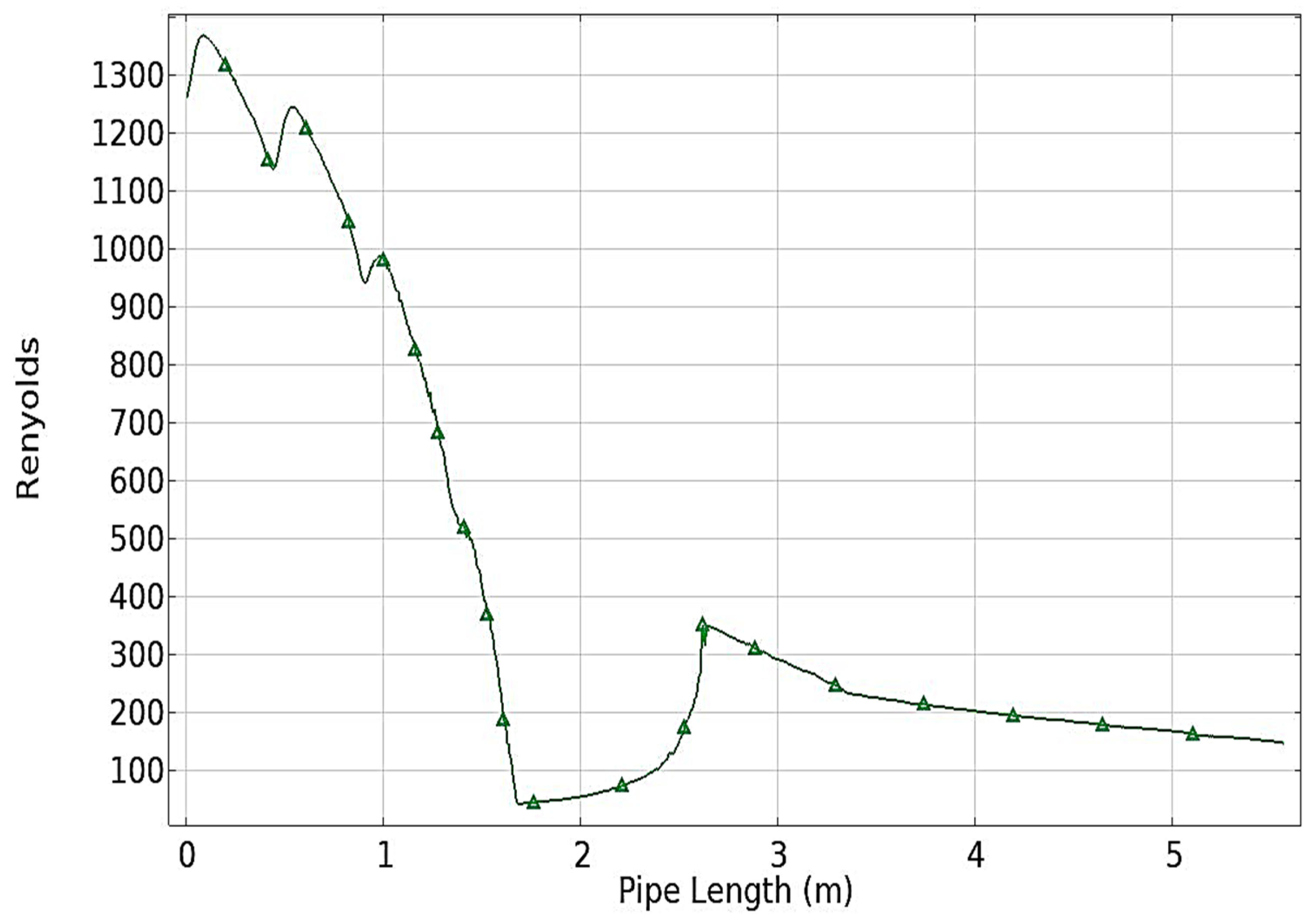
Figure 6 illustrates the non-uniform distribution of Reynolds number (Re) along the pipe length, which is attributed to the phase change occurring within the material. The maximum Reynolds number observed is 1366, corresponding to a Dean number (De) of 259. The phase change takes place at a pipe length of approximately 1.7 m, where the number of Reynolds drops significantly to 41. This indicates a transition in the fluid flow regime, likely caused by the phase transition from liquid to vapor. The graph clearly shows a substantial fluctuation in Reynolds number at the phase change point, followed by stabilization as the flow reaches a new equilibrium state. This behavior highlights the complex interaction between heat transfer and fluid dynamics during the phase transition.
Figure 6. Reynolds Number vs. Pipe Length.
The observed fluctuations in Re (from 701 to 1366, then to 41) reflect phase transition behavior, not inconsistency.
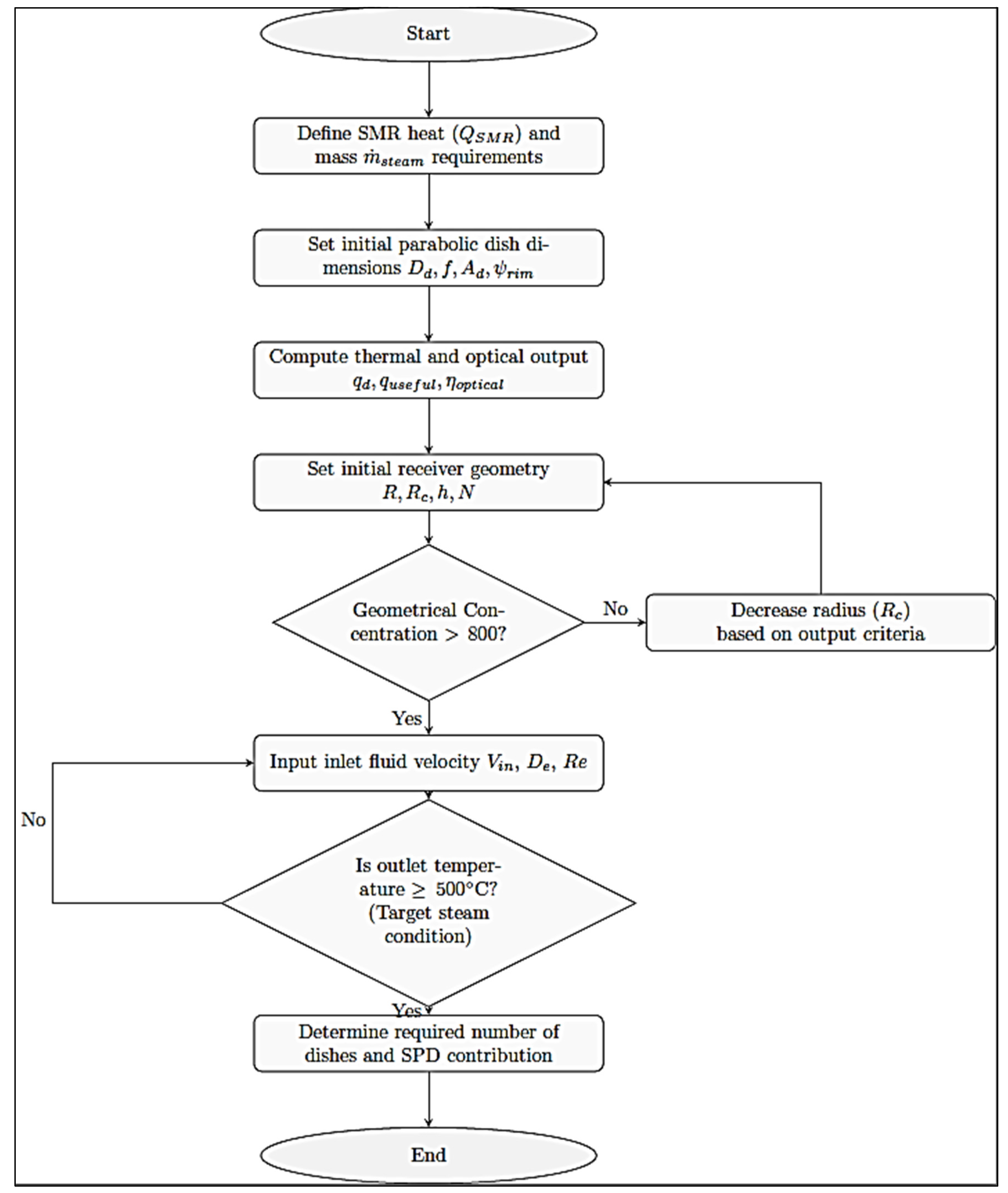
The approach of Figure 7 includes defining thermal load, sizing the dish and receiver, and verifying if the outlet temperature and flow regime (Re > 1000) meet targets. If not, receiver geometry is adjusted iteratively. The process continues until the system achieves the desired thermal output and efficiency with a feasible number of dishes. The final design ensures both thermal and hydraulic performance requirements are met.
Figure 7. Flow chart of designing the SPD system.
Figure 7 illustrates the design workflow: (1) input process requirements, (2) calculate thermal load, (3) select dish and receiver geometry, (4) perform outlet temperature (5) adjust geometry iteratively, (6) finalize SPD configuration.

5. Results and Discussion

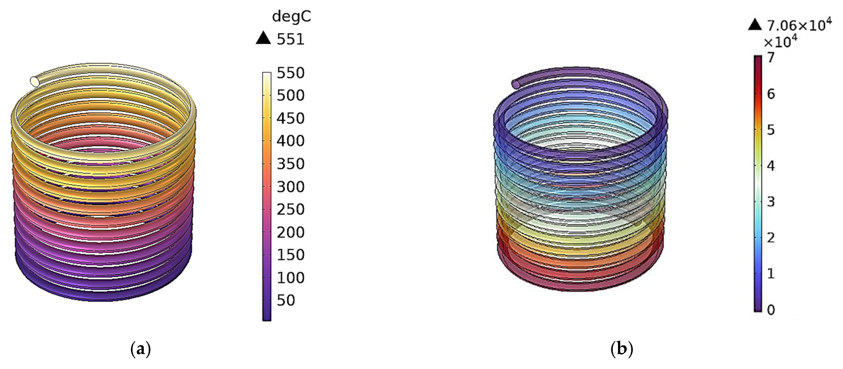
Figure 8 shows that the maximum outlet temperature reaches 857 K with a corresponding pressure drop of 706 kPa at an inlet velocity of 0.987 m/s and an inlet pressure of 30 bar. Since the Steam Methane Reforming (SMR) process requires a minimum outlet steam temperature of 327 °C, the fluid velocity is intentionally kept relatively low to accommodate the compact dimensions of the receiver. Although Sigalloti et al. [] recommend operating in the turbulent flow regime requiring higher velocities to enhance heat transfer, this would in turn necessitate larger receiver dimensions and increased pumping power. Therefore, optimization must be carried out to balance the benefits of lower velocities, which favor higher outlet temperatures, against the additional energy demand associated with higher fluid velocities.
Figure 8. Circular tube simulation (a) Temperature (K) and (b) Pressure (Pa).
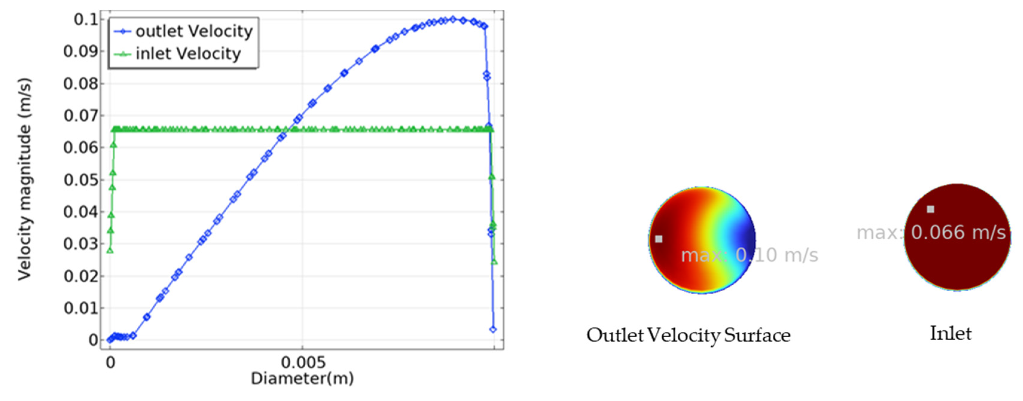
Although turbulent flow improves heat transfer, the laminar regime was preferred due to receiver constraints and the objective of maximizing outlet temperature. This behavior arises because lower velocities increase the residence time of steam within the receiver coil, allowing greater heat absorption and producing higher outlet temperatures. This trend was also reported by Sigalotti et al. [], reinforcing our findings. Figure 9 illustrates the velocity field along the tube, showing that as the fluid approaches the outlet, it is directed toward the left relative to the receiver. This behavior is attributed to the tube’s orientation.
Figure 9. The velocity field for inlet and outlet.
Figure 10 presents the profiles of DNI and outlet temperature (Tout). The DNI reaches a maximum of 1000 W/m2 between 12:00 and 13:00, while Tout attains a peak value of 857 K. The system is capable of sustaining the thermal energy requirements of SMR (above 623 K) for approximately 5 h per day. To enhance performance during off-peak periods, measures such as feedwater preheating or auxiliary heating can be employed. The predicted outlet temperature and flow behavior were validated against the results of Pavlovic et al. [] and Bellos et al. [], showing consistent trends in both thermal performance and pressure drop, thereby confirming the reliability of the developed model. Morning and evening efficiencies are lower, reducing average daily performance. These effects were accounted for in annualized savings estimates.
Figure 10. Daily Variation of DNI and Receiver Tout.
The design of the SPD was driven by the specific thermal requirements of the Steam Methane Reforming (SMR) process. The overall process flow, modeled in ASPEN Plus, identified key heating demands. The SPD was integrated to offset the energy required by the HEAT-H2O unit, which is responsible for preheating water and generating steam.
The boiler heating duty for the HEAT-H2O unit was calculated as 7785.2 kW (see Table 4), forming the baseline against which the SPD contribution of 778.5 kW (10%) was defined. The hybrid heating strategy was defined as follows:
Table 4. Process Heating Loads and SPD Contribution.
  • The SPD system was designed to supply 10% of the total heat duty for the HEAT-H2O unit.
  • This contribution translates to a solar thermal input of 778.5 kW for this specific duty.
  • The remaining 90% of the heat required by the HEAT-H2O unit, along with other process heaters (HEAT-CH4 and HEAT-MIX), is supplied by conventional natural gas boilers.
In the ASPEN Plus model, the HEAT-H2O unit represents water preheating and steam generation, HEAT-CH4 represents methane preheating, and HEAT-MIX corresponds to heating the feed mixture to 900 °C. The SPD was integrated only with HEAT-H2O, since this unit requires the largest fraction of process heating. This targeted integration approach allowed for a scalable and pragmatic design, where the SPD directly reduces the fossil fuel consumption of the most energy-intensive preheating step without compromising the reliability of the entire SMR process.
The SPD system was designed to supply 778.5 kW of thermal energy, covering 10% of the 7785.2 kW heating load of the HEAT-H2O unit. Operating for an average of 5 h per day at peak efficiency, this translates to a daily energy saving of 180 GJ/day.
  • Annual Fuel Savings: 328,500 SAR/year (based on natural gas at 5.31 SAR/GJ)
  • Annualized SPD Cost: 187,500 SAR/year (based on a 3.75 M SAR capital cost over 20 years)
  • Net Annual Savings: 141,000 SAR/year
Although fuel price fluctuations occurred, a fixed value of 5.31 SAR/GJ was used for baseline comparison.

6. Conclusions and Recommendations

This research successfully designed, modeled, and validated a solar parabolic dish (SPD) system for direct integration into an industrial Steam Methane Reforming (SMR) plant. The key outcomes and insights are:
  • Demonstrated Technical Feasibility: The optimized SPD system consistently delivers superheated steam at 551 °C, proving that concentrated solar thermal technology can reliably meet the high-temperature, high-pressure demands of major industrial processes like hydrogen production.
  • Precision Engineering through Integration: The SPD was not designed in isolation. Its specifications were directly derived from the ASPEN Plus process model to meet a precise heating load of 778.5 kW, covering 10% of the duty for the water preheater (HEAT-H2O unit). This ensures seamless and efficient integration into the overall plant layout.
  • Proven Economic and Environmental Value: The system generates net annual savings of 141,000 SAR by offsetting natural gas consumption, demonstrating that decarbonization can be economically advantageous. This directly reduces the carbon footprint of the blue hydrogen produced.
  • A Paradigm Shift in Solar Application: The core innovation of this work is a new application for CSP. We moved beyond power generation to demonstrate CSP’s role as a direct process heating partner for conventional industry, offering a pragmatic and scalable path to decarbonization.
  • A Replicable Blueprint for Industry: This study provides a generalizable design and integration framework. The methodology of linking process simulation with solar component design can be adapted for other energy-intensive sectors (e.g., cement, metals, chemicals), significantly amplifying its impact.
  • A Foundation for the Future: This work lays the groundwork for next-stage innovations, most notably the integration of thermal energy storage to extend operational hours and further increase the solar fraction, moving closer to a fully sustainable industrial heat supply.
In essence, this research proves that solar thermal energy is a viable, ready-to-deploy partner for heavy industry, transforming a major energy consumer into a more sustainable and cost-efficient operation. Future work will explore integrating thermal storage and higher solar fractions to extend operating hours and increase renewable contribution.

Author Contributions

Conceptualization, T.M., M.A.-Z., S.H., A.A., M.A. (Mohammad Aljohani), M.A. (Murad Alghamdi), F.A., L.A. and S.A.; methodology, T.M. and S.A.; software, T.M., A.A., S.H., M.A. (Mohammad Aljohani), M.A. (Murad Alghamdi) and F.A.; methodology, T.M., A.A., S.H., M.A. (Mohammad Aljohani), M.A. (Murad Alghamdi) and F.A.; validation, T.M., M.A.-Z., A.A., M.A. (Mohammad Aljohani), M.A. (Murad Alghamdi), F.A., L.A. and S.A.; methodology, T.M. and S.A.; formal analysis, T.M., M.A.-Z., A.A., M.A. (Mohammad Aljohani), M.A. (Murad Alghamdi), F.A., L.A. and S.A.; methodology, T.M. and S.A.; investigation, T.M. and S.A.; resources, T.M. and S.A.; data curation, T.M. and S.A.; writing—original draft preparation, T.M.; writing—review and editing, T.M., M.A.-Z., A.A., S.H., M.A. (Mohammad Aljohani), M.A. (Murad Alghamdi), F.A., L.A. and S.A.; methodology, T.M. and S.A.; visualization, T.M. and S.A.; supervision, T.M.; project administration, T.M. and M.A.-Z.; funding acquisition, T.M. All authors have read and agreed to the published version of the manuscript.

Funding

This research received no external funding.

Data Availability Statement

The data supporting this study’s findings are available from the corresponding author upon reasonable request.

Acknowledgments

We would like to acknowledge the Imam Abdulrahman Bin Faisal University for the assistance and support provided to conduct very efficient research. Thanks are also extended to Maaden Company (Riyadh, Saudi Arabia) for providing the red mud samples.

Conflicts of Interest

The authors declare no conflicts of interest.

Nomenclature

AbbreviationFull Term
DNIDirect Normal Irradiance (W/m2)
ψmMaximum solar dish angle
Cp-inHeat Capacity (kJ/kg·K)
ψrimRim angle of the dish
RcRadius of the receiver tube
γCurvature ratio
FFocal length of the dish
η o p t Optical Efficiency (%)
Mass flow rate (kg/s)
ReReynold number
T i n Inlet Temperature (°C)
T o u t Outlet Temperature

References

  1. Alami, A.H.; Olabi, A.G.; Mdallal, A.; Rezk, A.; Radwan, A.; Rahman, S.M.A.; Shah, S.K.; Abdelkareem, M.A. Concentrating Solar Power (CSP) Technologies: Status and Analysis. Int. J. Thermofluids 2023, 18, 100340. [Google Scholar] [CrossRef]
  2. Kopeinig, H. Renewable Energy Generation and Consumption in the Aggregate Sector. Master’s Thesis, Technical University of Leoben, Leoben, Austria, 2025. [Google Scholar]
  3. Sofiane, M. Design and Performance Optimization of Future Concentrated Solar Power Plants for Long-Duration Thermal Energy Storage: A Case Study. J. Renew. Energy Environ. 2025, 12, 56–70. [Google Scholar]
  4. Al-Amayreh, M.I.; Alahmer, A.; Manasrah, A. A Novel Parabolic Solar Dish Design for a Hybrid Solar Lighting-Thermal Applications. Energy Rep. 2020, 6, 1136–1143. [Google Scholar] [CrossRef]
  5. Shboul, B.; Khawaldeh, H.A.; Al-Smairan, M.; Alrbai, M.; Ali, H.H.; Almomani, F. Perspectives of New Solar Energy Option for Sustainable Residential Electricity Generation: A Comparative Techno-Economic Evaluation of Photovoltaic and Solar Dish Systems. Energy Rep. 2025, 13, 4514–4527. [Google Scholar] [CrossRef]
  6. Kumar, V.; Singh, U.R.; Bhogilla, S.S. Experimental Investigation of an Innovative PV/T Collector in Jammu Climatic Conditions. Therm. Sci. Eng. Prog. 2025, 59, 103312. [Google Scholar] [CrossRef]
  7. Pavlović, S.R.; Vasiljević, D.M.; Stefanović, V.P.; Stamenković, Z.M.; Bellos, E.A. Optical Analysis and Performance Evaluation of a Solar Parabolic Dish Concentrator. Therm. Sci. 2016, 20, 1237–1249. [Google Scholar] [CrossRef]
  8. Pavlovic, S.; Bellos, E.; Loni, R. Exergetic Investigation of a Solar Dish Collector with Smooth and Corrugated Spiral Absorber Operating with Various Nanofluids. J. Clean. Prod. 2018, 174, 1147–1160. [Google Scholar] [CrossRef]
  9. Ubando, A.T.; Conversion, A.; Barroca, R.B.; Enano, N.H., Jr.; Espina, R.U. Computational Fluid Dynamics on Solar Dish in a Concentrated Solar Power: A Bibliometric Review. Solar 2022, 2, 251–273. [Google Scholar] [CrossRef]
  10. Malik, M.Z.; Shaikh, P.H.; Zhang, S.; Lashari, A.A.; Leghari, Z.H.; Baloch, M.H.; Memon, Z.A.; Caiming, C. A Review on Design Parameters and Specifications of Parabolic Solar Dish Stirling Systems and Their Applications. Energy Rep. 2022, 8, 4128–4154. [Google Scholar] [CrossRef]
  11. Abed, A.A.; El-Marghany, M.R.; El-Awady, W.M.; Hamed, A.M. Recent Advances in Parabolic Dish Solar Concentrators: Receiver Design, Heat Loss Reduction, and Nanofluid Optimization for Enhanced Efficiency and Applications. Sol. Energy Mater. Sol. Cells 2024, 273, 112930. [Google Scholar] [CrossRef]
  12. Korawan, A.D. Karakteristik penyimpan kalor laten pada parabolic mirror dish. J. Penelit. dan Pengabdi. Kpd. Masy. UNSIQ 2023, 10, 8–12. [Google Scholar] [CrossRef]
  13. Alkhalaf, Q.; Lee, D.; Kumar, R.; Thapa, S.; Singh, A.R.; Akhtar, M.N.; Asif, M.; Ağbulut, Ü. Experimental Investigation of the Thermal Efficiency of a New Cavity Receiver Design for Concentrator Solar Technology. Case Stud. Therm. Eng. 2024, 53, 103848. [Google Scholar] [CrossRef]
  14. Kopalakrishnaswami, A.S.; Natarajan, S.K. Comparative Study of Modified Conical Cavity Receiver with Other Receivers for Solar Paraboloidal Dish Collector System. Environ. Sci. Pollut. Res. 2022, 29, 7548–7558. [Google Scholar] [CrossRef]
  15. Arjun Singh, K.; Natarajan, S.K. Thermal Analysis of Modified Conical Cavity Receiver for a Paraboloidal Dish Collector System. Energy Sources Part A Recovery Util. Environ. Eff. 2021, 47, 1–12. [Google Scholar]
  16. Bellos, E.; Bousi, E.; Tzivanidis, C.; Pavlovic, S. Optical and Thermal Analysis of Different Cavity Receiver Designs for Solar Dish Concentrators. Energy Convers. Manag. X 2019, 2, 100013. [Google Scholar] [CrossRef]
  17. Malviya, R.; Baredar, P.V.; Kumar, A. Thermal Performance Improvement of Solar Parabolic Dish System Using Modified Spiral Coil Tubular Receiver. Int. J. Photoenergy 2021, 2021, 4517923. [Google Scholar] [CrossRef]
  18. Wang, F.; Shuai, Y.; Yuan, Y.; Liu, B. Effects of Material Selection on the Thermal Stresses of Tube Receiver under Concentrated Solar Irradiation. Mater. Des. 2012, 33, 284–291. [Google Scholar] [CrossRef]
  19. Hameed, H.G.; Diabil, H.A.N.; Al-Fahham, M.A. Performance Study on a Solar Concentrator System for Water Distillation Using Different Water Nanofluids. Heliyon 2023, 9, e16535. [Google Scholar] [CrossRef]
  20. Abu-Zeid, M.A.-R.; Elhenawy, Y.; Toderaș, M.; Bassyouni, M.; Majozi, T.; Al-Qabandi, O.A.; Kishk, S.S. Performance Enhancement of Solar Still Unit Using V-Corrugated Basin, Internal Reflecting Mirror, Flat-Plate Solar Collector and Nanofluids. Sustainability 2024, 16, 655. [Google Scholar] [CrossRef]
  21. Sigalotti, L.D.G.; Alvarado-Rodríguez, C.E.; Rendón, O. Fluid Flow in Helically Coiled Pipes. Fluids 2023, 8, 308. [Google Scholar] [CrossRef]
  22. Avargani, V.M.; Zendehboudi, S. Parametric Analysis of a High-Temperature Solar-Driven Propane Steam Reformer for Hydrogen Production in a Porous Bed Catalytic Reactor. Energy Convers. Manag. 2023, 276, 116539. [Google Scholar] [CrossRef]
  23. Thakkar, V.; Doshi, A.; Rana, A. Performance Analysis Methodology for Parabolic Dish Solar Concentrators for Process Heating Using Thermic Fluid. J. Mech. Civ. Eng. 2015, 12, 101–114. [Google Scholar]
Disclaimer/Publisher’s Note: The statements, opinions and data contained in all publications are solely those of the individual author(s) and contributor(s) and not of MDPI and/or the editor(s). MDPI and/or the editor(s) disclaim responsibility for any injury to people or property resulting from any ideas, methods, instructions or products referred to in the content.

Article Metrics

Citations

Article Access Statistics

Multiple requests from the same IP address are counted as one view.