Hydrogen-Enabled Power Systems: Technologies’ Options Overview and Effect on the Balance of Plant
Abstract
1. Introduction
2. Method
3. Water Electrolysis
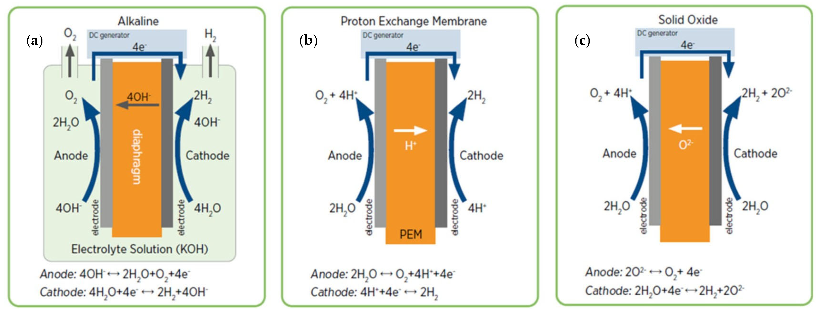
3.1. Electrolysis Technologies
Electrolysers Emerging Technologies
- Anion Exchange Membrane Electrolyser (AEME) possesses the advantages of both ALKE and PEM electrolysers technologies without their weak points [63].
- Proton-Conducting Ceramic Electrolyser (PCCE) is another emerging high-temperature and comparably high-efficiency technology.
- Unitized Regenerative Fuel Cell (URFC) is an electrolyser and FC in one stack arrangement, which can carry out the electrolysis of water in electrolysis mode and function in regenerative mode as a FC. The combination of both electrolysers and FCs in a single cell/stack requires special arrangements and engineering controls [64].
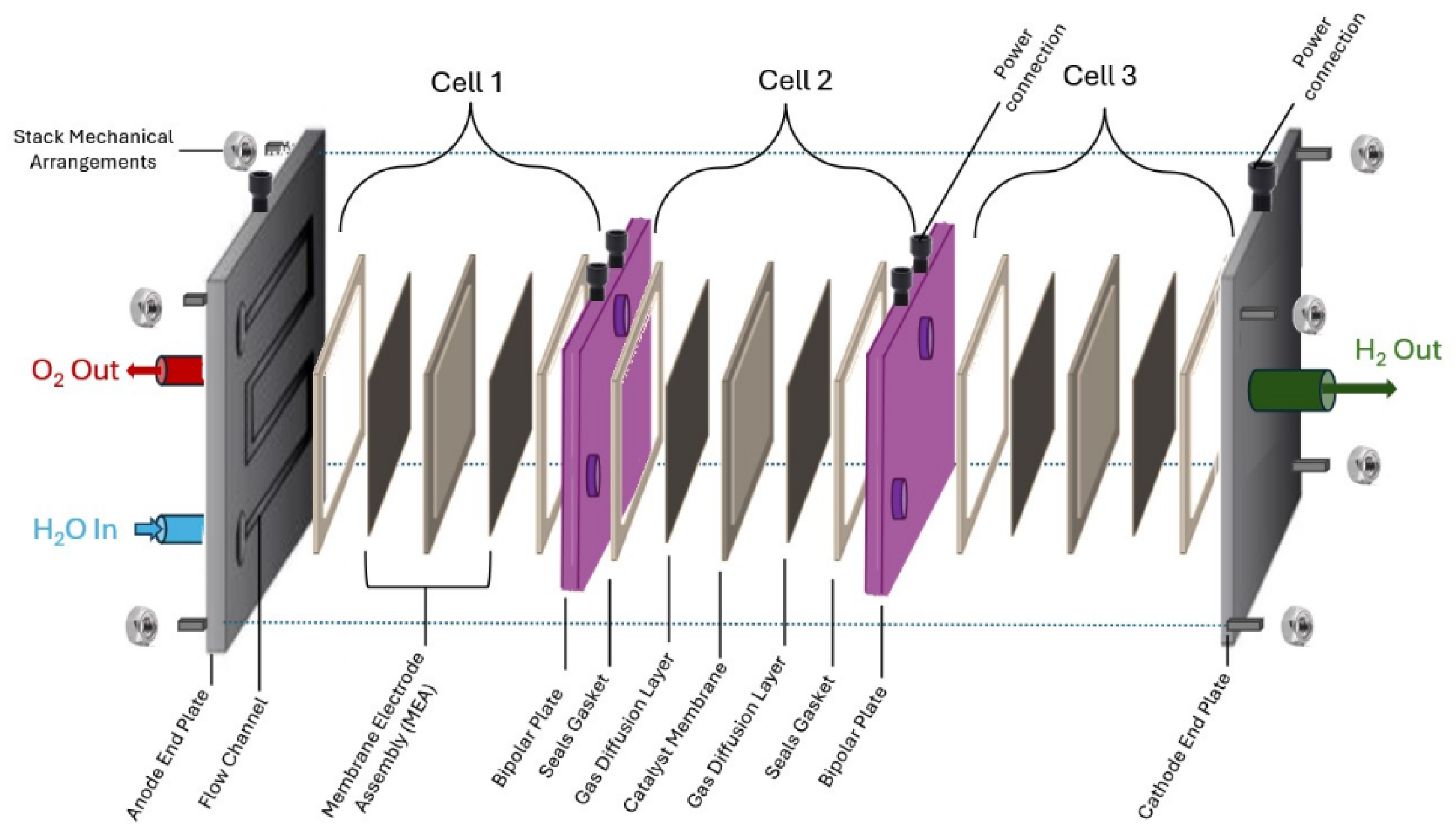
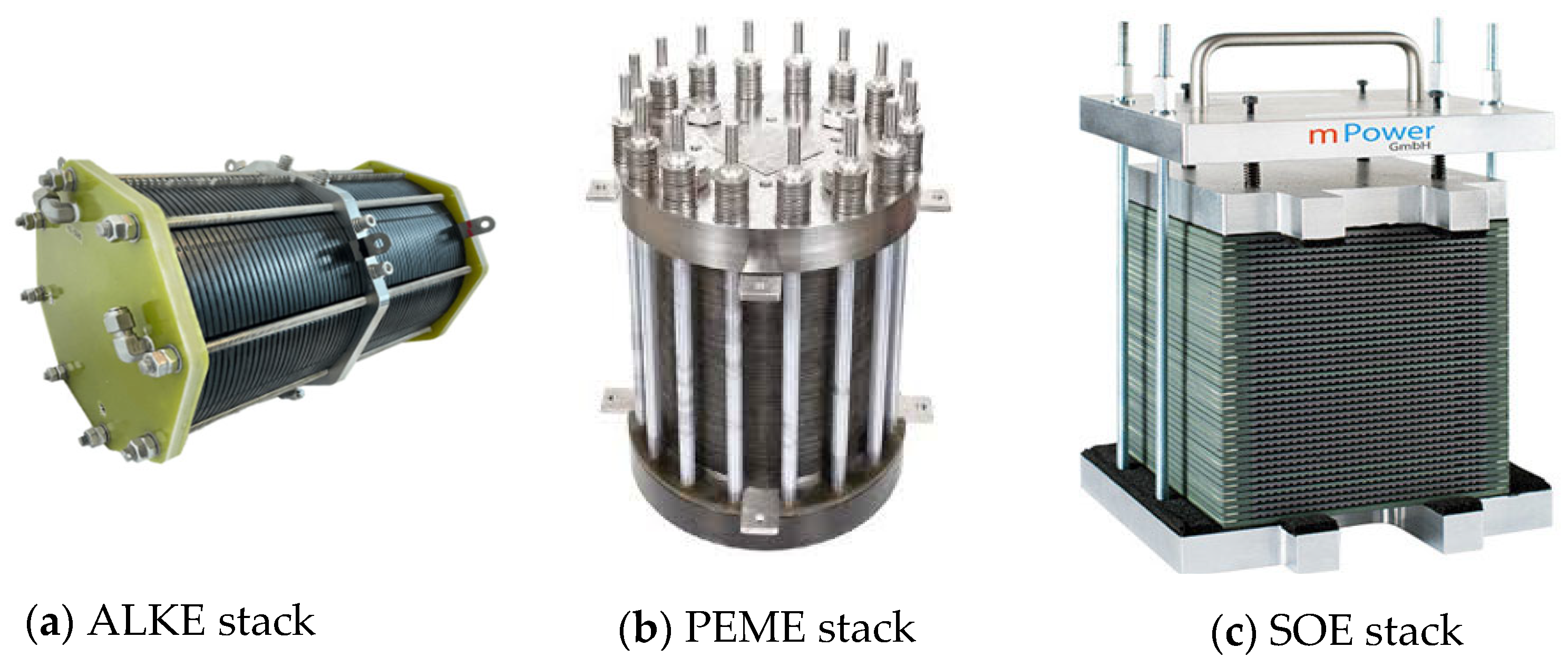
3.2. Electrolyser’s Cell and Stack Arrangements
- The Membrane Electrode Assembly (MEA) consist of the following:
- a.
- Electrodes (anode and cathode);
- b.
- Catalyst (technology-specific);
- c.
- Membrane/Electrolyte (technology specific);
- d.
- Gas diffusion layer.
- Flow plates.
- Gaskets, clamping mechanism and seals.
- Feed stock (water) flow interconnection and recirculate water.
- Bipolar plates interconnecting cells back to back (anode to cathode).
- Anode and Cathode end plates at both ends of the stack.
- Cooling plates (coolant flow).
- Power connection arrangements.
- Stack mechanical arrangements, such as the following:
- a.
- Bolts;
- b.
- Layers’ stiffness;
- c.
- Machining gaskets;
- d.
- Seals;
- e.
- Clamping mechanism.
3.3. Electrolyser Package
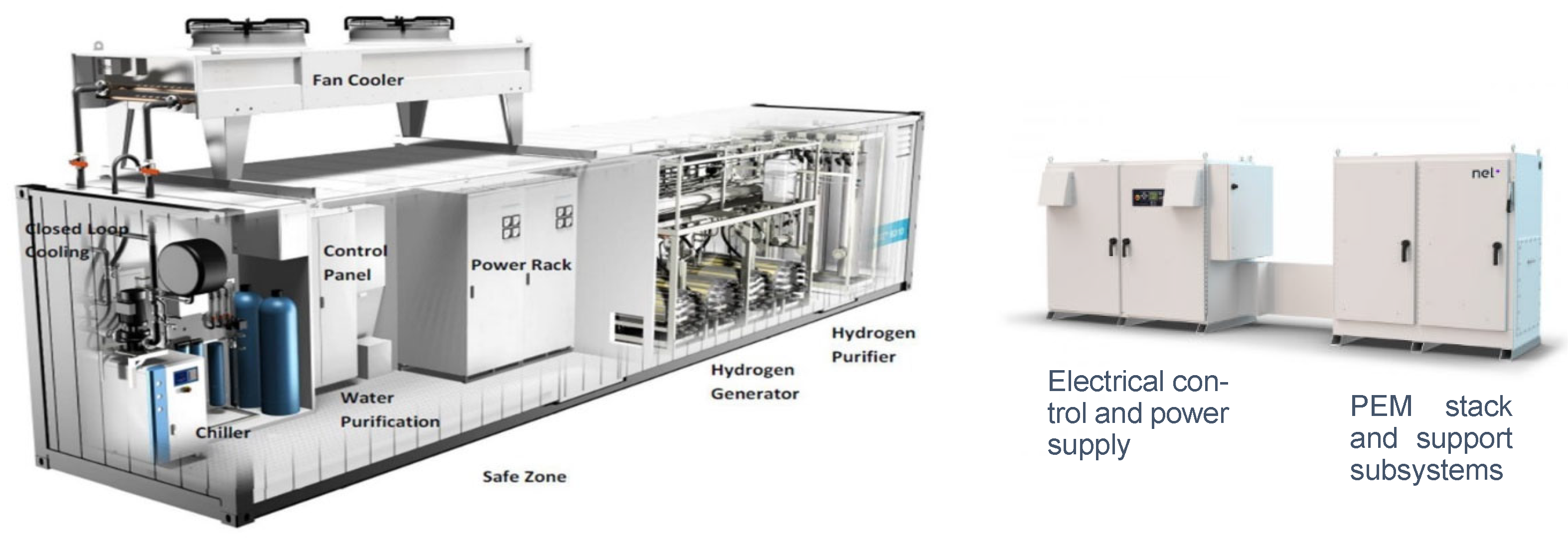
- Power supply rack (transformer and/or rectifier), Power Management System (PMS) and production control.
- Water supply, including storage, treatment such as desalination and/or purification and de-ionisation, and feeding systems, such as water pumping.
- Liquid electrolyte storage and circulating system (lye system) for the AKLE [76] or ion exchanger circulating system for the PEME.
- Cooling system and/or heat exchangers.
- Pressure control system.
- Monitor, control, and Human interface, including remote control, communication, software, and PLC.
- Hydrogen buffer tank.
- Hydrogen purification system, i.e., impurities removal and deoxygenation to remove remnant oxygen.
- Hydrogen dryers.
- Ventilation system.
- Venting valves and pipework.
- Sensors and alarm system.
- Interconnecting wires and pipelines.
4. Fuel Cells
4.1. Fuel Cell Technologies
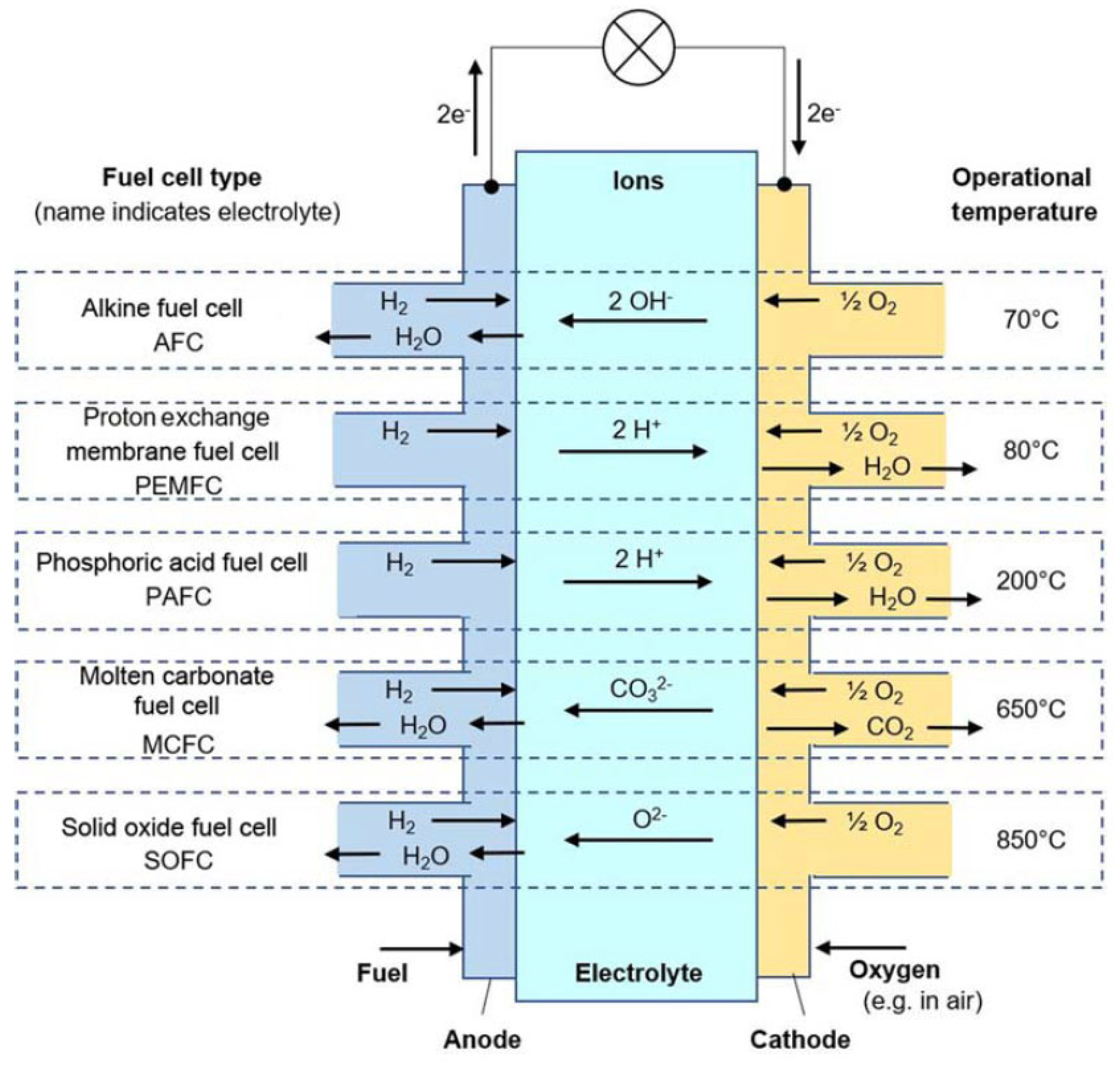
- Alkaline Electrolyte (AFC);
- Proton-Exchange Membrane (PEMFC);
- Phosphoric Acid PAFC;
- Molten Carbonate (MCFC);
- Solid Oxide (SOFC).
Fuel Cells Emerging Technologies
4.2. Fuel Cell Package
Key Differences Between Electrolysers and Fuel Cell Stack Designs
- (1)
- Electrode materials.
- (2)
- Electrolyte type.
- (3)
- Operating conditions, such as operating heat and pressure.
- (4)
- Gas management, i.e., modified, or different geometry.
- (5)
- Auxiliary and sub-systems, e.g., air instead of water pumping system.
- (6)
- Cell connections.
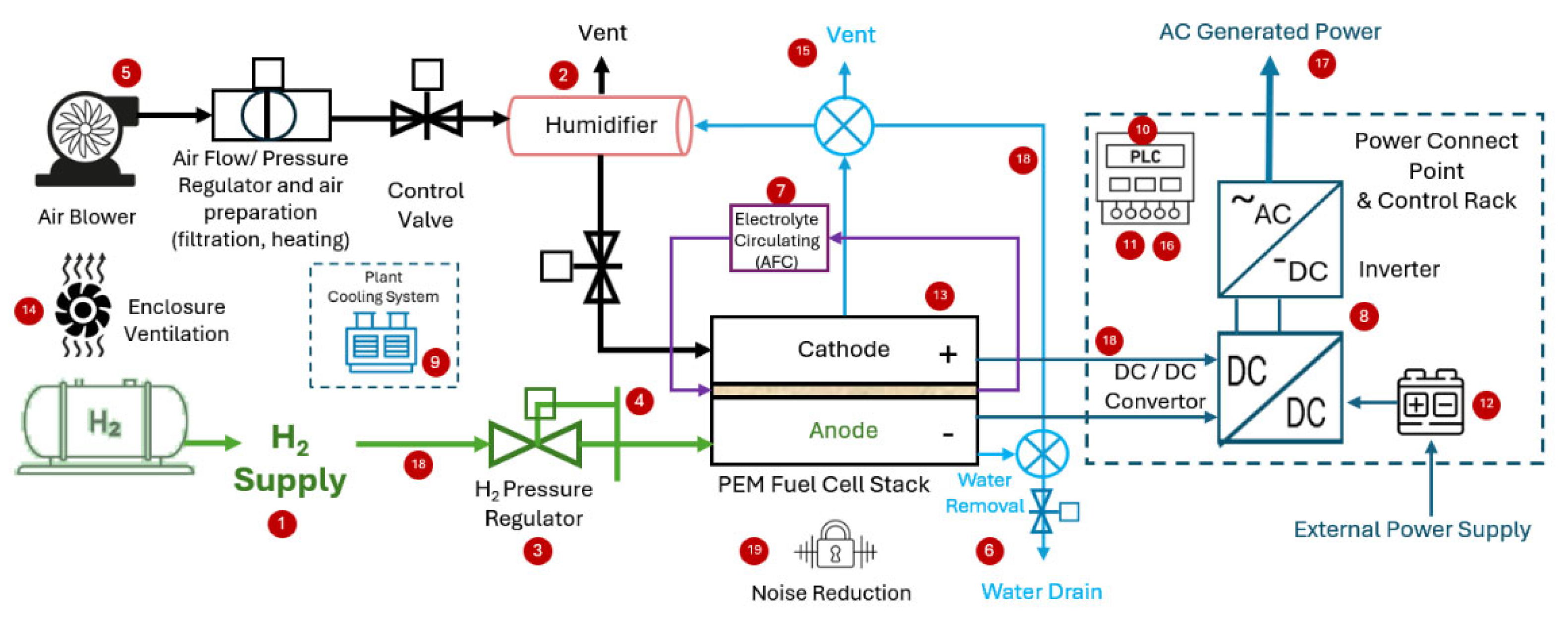
- Hydrogen recycling system for re-use of unconsumed hydrogen [81].
- Water management, i.e., water removal (prevent flooding), water purge (prevents freeze-out damage if the ambient temperature falls below zero °C), drainage and/or reclaim unit, typically a condenser and water pump [81].
- Electrolyte circulating system for FCs using liquid electrolyte, i.e., AFC, typically a tank and pump with pipes [103].
- Overall control is called Fuel Cell Control Unit (FCCU) [90].
- Human–Machine Interface (HMI) and PLC interface for remote control [104].
- Enclosure ventilation system to prevent hydrogen leakage (if any) from accumulating within the closure [81].
- Venting valves and pipework [100].
- Electrical interconnecting wires [81].
- Pipework (hydrogen, air and water) [100].
- Operating noise reduction mechanism [107].
5. Hydrogen Storage
5.1. Technologies
5.2. Physical-Based Storage Technologies: BoP
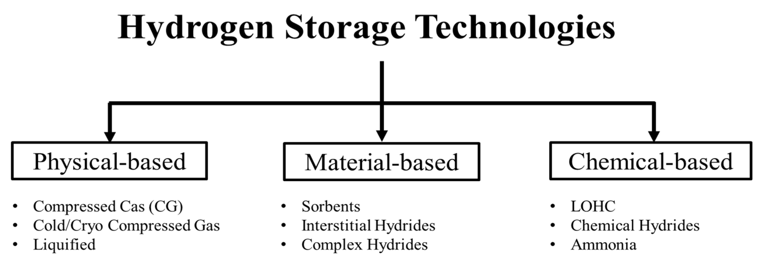
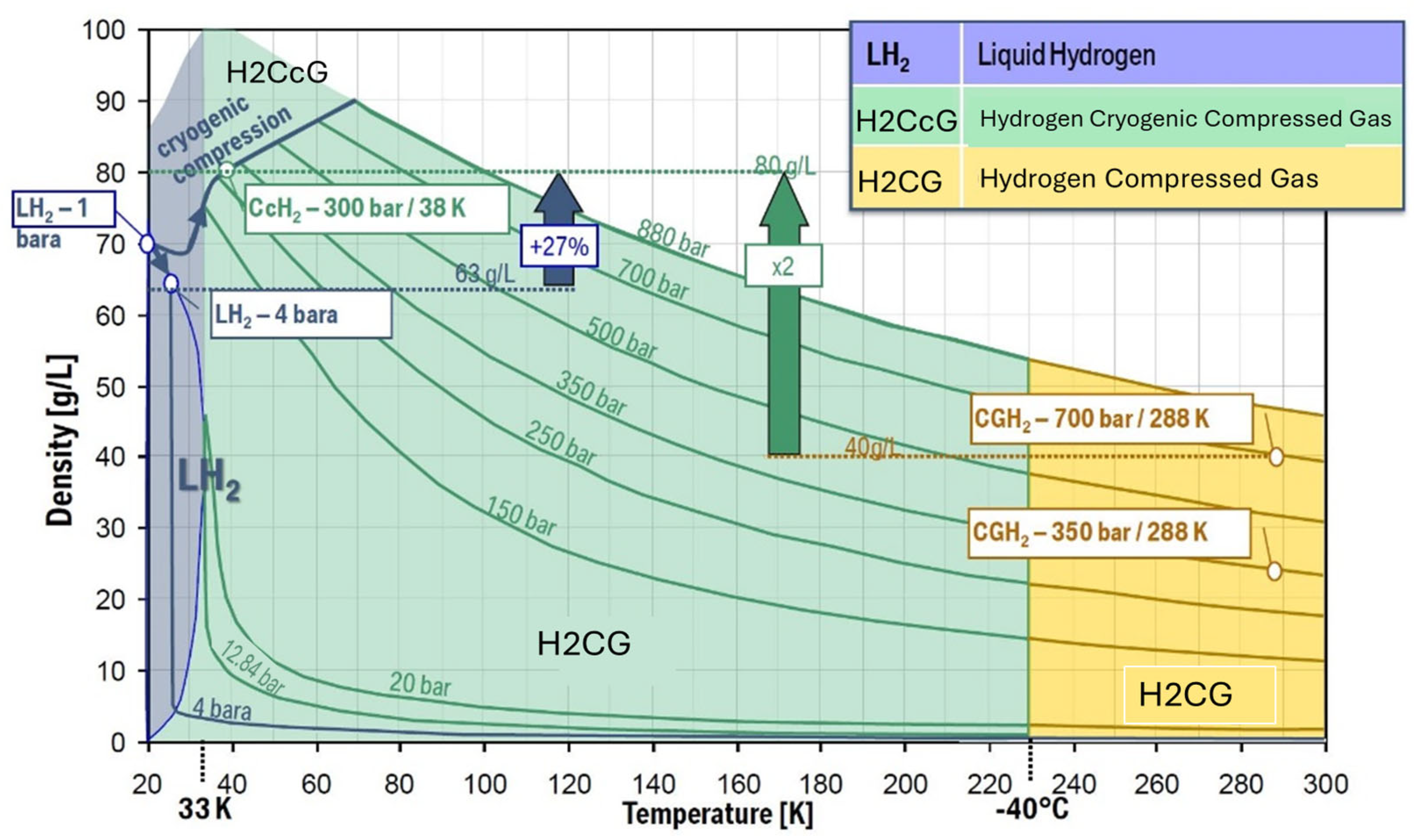
- Hydrogen Compressed Gas (H2CG) operates at high pressures, as high as 70 MPa, and near ambient temperature.
- Hydrogen Cryo-compressed Gas (H2CcG) typically operates at around and above 350 bars and temperatures less than −120 °C (150 K).
- Liquid hydrogen (also called Cryogenic Liquid) operates at low pressures, i.e., typically less than 6 bars (<0.6 MPa) and low temperatures near the normal boiling point of the hydrogen, i.e., −253 °C (20 K).
5.2.1. Compressed Gas Package
- The compressor unit (package) type depends on the required pressure, mass flow rate, and technology’s techno-economic choice [110,111]. The compressor is the main part of H2CG technology, which operates as an intermediate system between the production and the storage vessel. Typically, the compressor unit is delivered from the OEM as a fully functioning unit packaged in one or more enclosures, which includes the following [25]:
- (a)
- Power supply switchboard (depends on the compressor size).
- (b)
- Bypass and pressure relief valves (manual or auto-actuated).
- (c)
- Hydrogen and purge gas venting system.
- (d)
- Control system and/or PLC unit (depending on the size of the system and its integration into the holistic H2PS requirements) for operations and remote control, if required.
- (e)
- Safety systems, including hydrogen detectors, shut-off (stop) functions, and alarm systems, are typically automatic.
- (f)
- Compressed air system and pipework if valves are air-actuated.
- (g)
- Compressor cooling system for internal and compressed hydrogen outlet cooling. Cooling the outlet compressed hydrogen gas depends on the mass flow rate and the operating temperature of the storage vessel.
- (h)
- Hydrogen pipelines.
- 2.
- Storage vessels are typically cylinders where the compressed hydrogen is stored within. The storage vessels system, in general, includes the following:
- (a)
- Storage vessel, where its type depends on the operation pressure, footprint, application, and cost-effectiveness.
- (b)
- Check and shut off (isolation) valves, safety raptures, inlet/outlet valves, and pipelines.
- (c)
- Ventilation system in the case of enclosed storage vessels.
- (d)
- Control system for operations and remote control (if required).
- (e)
- Safety systems, including leak detectors, isolation valves, and alarm systems.
- (f)
- Compressed air system and pipelines (if valves are air-actuated).
- (g)
- Venting system for hydrogen and purging gas.
5.2.2. Cryogenic Compressed Gas and Liquifying Package
- (a)
- (b)
- Cryogenic and/or liquid hydrogen containers (vessels), typically made of stainless steel and aluminium [114], are specifically designed to reduce heat leakage by thermal insulation. The H2CcG and LH2 vessels must be specifically designed to handle extremely low temperatures [115]. Specifically, LH2 tanks are expected to be built at larger (capacity) units compared to H2-CG tanks, as they do not handle high pressure [116]. Additionally, in LH2 plants, liquid hydrogen boiloff management system is crucial to reduce the heat transfer (losses) from the surroundings when hydrogen is stored for a long time [17,116].
- (c)
- (d)
- A hydrogen boiloff venting system is crucial, and safety concerns must be addressed as vented cold hydrogen is denser than ambient air and may fall back to the plant grounds [118].
- (e)
- Cryogenic pumps transfer LH2 from the vessel to the vaporiser and/or the buffer tanks [103].
5.3. Material-Based Storage Technologies: BoP
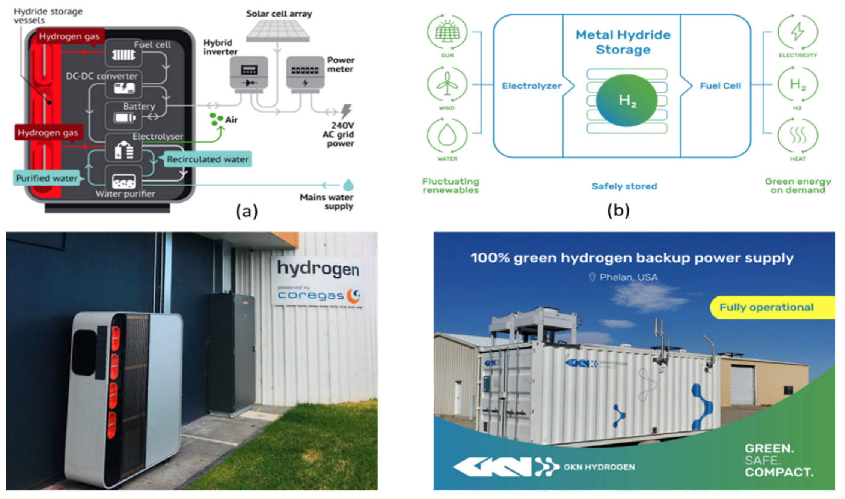
- A thermal management system controls the hydrogen uptake (hydrogenation) and the release at the required flow rate [92]. The uptake reaction is exothermic; i.e., heat has to be removed while heat is required to enable the endothermic decomposition of the hydride (dehydrogenation) [123]. Therefore, the released hydrogen must be cooled and compressed to the FC inlet-specific operation pressure [124]. The required release heat, typically, can be obtained from an external source or utilise the heat releases from the regenerating package, i.e., the FC [123]. The external heat energy can be obtained from burning a portion of the released hydrogen to control the release flow rate [124], which adds complexity to the package. The H2PS-associated battery may be used for the startup of the release process. Also, the package includes a cooling and/or cryogenic refrigerator for the intake process and control [125].
- The material-specific storage vessel type and specific design depend on the type of material in use, storage size, operating pressure, and temperature range.
- Typically, the package requires moisture sensors in addition to the H2 and O2 sensors [124].
- A hazardous waste-materials disposal management system depends on the type of storage material and the system operation conditions [85].
- A low-pressure compressor might be required (depending on the storage system H2 release pressure) to pressure the released H2 to the FC inlet operating pressure [124].
- Power supply switchboard (depends on the compressor size and the thermal management technology).
- Pressure relief valves (typically auto-actuated).
- Hydrogen and purge gas (typically nitrogen) venting system.
- Control system and/or PLC unit (depending on the system’s size and integration requirements into the H2PS) for operations and remote control (if required).
- Safety systems include a shut-off (stop) function and an alarm system, typically automatic.
- Compressed air system and pipelines (if valves are air-actuated).
- Compressor cooling system for internal cooling and the released H2 cooling after compression.
5.4. Chemical-Based (Hydrogen Carriers): BoP
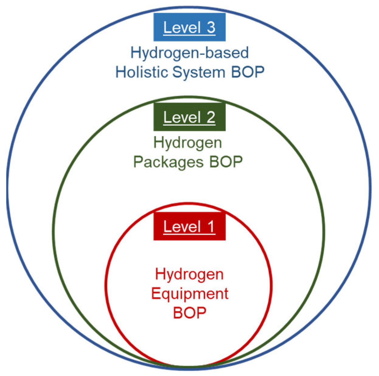
6. Holistic H2PS Systems’ BoP
6.1. Non-Hydrogen Auxiliary and Sub-Systems
- Renewable Energy (RE) power generation plants, such as solar PV, wind turbines, oceanic energy, etc., depend on the area’s RE resources availability, whilst the plant size is related to the scale of the H2PS.
- Water supply, storage, and purification systems and related pipework, whereby complexity depends on the H2PS scale and water sources, i.e., seawater, underground, or potable water.
- The cooling system and its related pipework depend on the H2PS scale and packages’ technologies, i.e., the cooling requirements.
- The compressed air system depends on the H2PS scale and the pneumatic devices in use.
- Non-product stream treatment and disposal include brine water, coolant, lubricants, and any other waste related to specific technologies in use. The treatment and disposal process shall follow environmental codes and regulations at all levels.
- Point of connection switchboard and electrical connections to and from the H2PS I/O terminals, i.e., cables, trays, converters, inverters, and protection systems. The electrical equipment shall be compatible with an explosive atmosphere requirement, depending on the safe distance from the hydrogen environment.
- Electrical buffer system to manage the load rejection and shedding, as well as the start-ups and shutdowns of the H2PS equipment. These buffers are typically batteries and/or supercapacitor banks. The buffer system’s size depends on the scale of the H2PS and the hosting or served power system size and orientation.
- Fire detection and suppression systems associated with the holistic H2PS.
- Civil work and safeguards include concrete foundations, footpaths, heavy machinery access, barriers, and fences. Note: Civil works are out of the scope of this study.
6.2. Interconnections and Interoperability
6.2.1. Production-Storage Packages’ Interconnection
- (1)
- Hydrogen transfer pipework with proper mechanical support and safety valves.
- (2)
- The hydrogen buffer (bladder) tank depends on the storage package inlet operation pressure and control philosophy.
- (3)
- Control, sensors, and communication commands (PLCs) wiring with proper mechanical support.
- (4)
- The cooling system that is typically part of the holistic H2PS cooling system but can be part of one or both supplied packages.
- (5)
- A heat recovery system for CHP can be used in thermal management when material-based or cryogenic storage technology is used.
- (6)
- A battery bank or buffer unit can be included in the electrolyser package or the holistic H2PS.
6.2.2. Storage-Regenerative (FC) Packages’ Interconnection
- (1)
- Hydrogen transfer pipework with proper mechanical support and safety valves.
- (2)
- Hydrogen pressure reduction skid when high-pressure storage technology is in use or a low-pressure compressor when using low-pressure material-based or LH2 storage technology. The pressure regulation depends on the FC package inlet operating pressure and the control philosophy.
- (3)
- Control, sensors, and communication commands (PLCs) wiring with proper mechanical support.
- (4)
- The cooling system that is typically part of the holistic H2PS cooling system but can be part of one or both supplied packages.
- (5)
- Heat recovery system for CHP or to control the hydrogen release flow rate when using material-based or LH2 storage technology.
- (6)
- Reclaimed water and transferred from the FC to the water supply system, which depends on the FC technology, operating temperature, and water scarcity.
- (7)
- The DC/DC converter unit can be included in the FC package or associated with the external DC/AC inverter, which is the gateway to the point of connection.
- (8)
- The auxiliary power supply, typically a battery bank, can be included in the FC package or the holistic H2PS. Also, it could be an external power supply.
6.3. Off-the-Shelf Engineered-Packaged Systems
6.4. Technologies’ Selection: Cause and Effect
7. Conclusions and Way Forward
Funding
Conflicts of Interest
Abbreviations
| H2PS | Hydrogen-based Power Systems |
| OEM | Original Equipment Manufacturer |
| BoP | Balance of Plant |
| RE | Renewable Energy |
| H2CG | Hydrogen Compressed Gas |
| EDO | Engineering Design and Operations |
| DC | Direct Current |
| ALKE | Alkaline Electrolyser |
| PEME | Proton Exchange Membrane Electrolyser |
| SOE | Solid Oxide Electrolyser |
| CHP | Combined Heat and Power |
| AEME | Anion Exchange Membrane Electrolyser |
| PCCE | Proton-Conducting Ceramic Electrolyser |
| URFC | Unitized Regenerative Fuel Cell |
| CFE | Capillary-fed Electrolysers |
| MEA | Membrane Electrode Assembly |
| PMS | Power Management System |
| FC | Fuel Cell |
| PAFC | Phosphoric Acid Fuel Cell |
| MCFC | Molten Carbonate Fuel Cell |
| DBFC | Direct Borohydride Fuel Cell |
| MFC | Microbial Fuel Cell |
| DMFC | Direct Methanol Fuel Cells |
| HMI | Human–Machine Interface |
| PLC | Programmable Logic Controller |
| FCCU | Fuel Cell Control Unit |
| STP | Standard Temperature and Pressure |
| H2CcG | Hydrogen Cryo-compressed Gas |
| LH2 | Liquid Hydrogen |
| LOHC | Liquid Organic Hydrogen Carrier |
References
- Dawood, F.; Anda, M.; Shafiullah, G.M. Hydrogen production for energy: An overview. Int. J. Hydrogen Energy 2020, 45, 3847–3869. [Google Scholar] [CrossRef]
- IRENA (International Renewable Energy Agency). Geopolitics of the Energy Transformation the Hydrogen Factor; International Renewable Energy Agency: Abu Dhabi, United Arab Emirates, 2022. [Google Scholar]
- Lund, C.; Islam, F.D.K.; Shafiullah, G.M.; Anda, M.; Bahri, P. Hybrid Solar Pv-Battery-Hyrdorgen System for Renewable Energy Standalone Microgrid Development; Murdoch University: Perth, WA, Australia, 2023. [Google Scholar]
- Al Ghafri, S.Z.S.; Revell, C.; Di Lorenzo, M.; Xiao, G.; Buckley, C.E.; May, E.F.; Johns, M. Techno-economic and environmental assessment of LNG export for hydrogen production. Int. J. Hydrogen Energy 2023, 48, 8343–8369. [Google Scholar] [CrossRef]
- Salehi, F.; Abbassi, R.; Asadnia, M.; Chan, B.; Chen, L. Overview of safety practices in sustainable hydrogen economy—An Australian perspective. Int. J. Hydrogen Energy 2022, 47, 34689–34703. [Google Scholar] [CrossRef]
- Srinivasan, V.; Delaval, B.; Dollman, R.; Towns, A.; Charnock, S.; Palfreyman, D.; Hayward, J.; Graham, P.; Foster, J.; Reedman, L.; et al. Renewable Energy Storage Roadmap; CSIRO: Canberra, Australia, 2023.
- Dawood, F. Hydrogen-Based Power Systems Evolution and Applications: An Engineering Design and Operation Advisory Model. Ph.D. Thesis, Murdoch University, Perth, WA, Australia, 2023. [Google Scholar]
- Colpan, C.O. Fuel Cell and Hydrogen Technologies in Aviation; Springer: Cham, Switzerland, 2022. [Google Scholar]
- Furat, D.; Shafiullah, G.M.; Martin, A. Stand-Alone Microgrid with 100% Renewable Energy: A Case Study with Hybrid Solar PV-Battery-Hydrogen. Sustainability 2020, 12, 2047. [Google Scholar] [CrossRef]
- Arup Australia Pty Ltd. Australian Hydrogen Hubs Study; COAG Energy Council Hydrogen Working Group: Sydney, Australia, 2019. Available online: https://www.dcceew.gov.au/sites/default/files/documents/nhs-australian-hydrogen-hubs-study-report-2019.pdf (accessed on 11 June 2023).
- CSIRO. HyResource. Available online: https://research.csiro.au/hyresource/ (accessed on 11 June 2023).
- AHC. Regulations and Standards. Available online: https://h2council.com.au/policy-regulation/standards (accessed on 11 June 2023).
- CSIRO. Hyresearch. Available online: https://research.csiro.au/hyresource/projects/rd/ (accessed on 11 June 2023).
- Power, H. Horizon Power Denham Hydrogen Demonstration; ARENA: Canberra, Australia, 2020. Available online: https://arena.gov.au/assets/2023/04/horizon-power-denham-hydrogen-demonstration-lessons-learnt-1-2.pdf (accessed on 11 June 2023).
- CSIRO. Hyresource-Projects. Available online: https://research.csiro.au/hyresource/projects/ (accessed on 11 June 2023).
- The Hydrogen Strategy Group. Hydrogen for Australia’s Future; The Hydrogen Strategy Group: Canberra, Australia, 2018. Available online: https://www.chiefscientist.gov.au/sites/default/files/HydrogenCOAGWhitePaper_WEB.pdf (accessed on 11 June 2023).
- Kotchourko, A.; Jordan, T. Hydrogen Safety for Energy Applications—Engineering Design, Risk Assessment, and Codes and Standards; Elsevier: Amsterdam, The Netherlands, 2022. [Google Scholar]
- Shet, S.P.; Shanmuga Priya, S.; Sudhakar, K.; Tahir, M. A review on current trends in potential use of metal-organic framework for hydrogen storage. Int. J. Hydrogen Energy 2021, 46, 11782–11803. [Google Scholar] [CrossRef]
- Dawood, F.; Shafiullah, G.M.; Anda, M. 100% Renewable Energy: A Stand-alone Hybrid Solar PV-Hydrogen-Battery Power Systems for Homeland Communities in Regional Western Australia. In Transition Towards a Carbon Free Future: Selected Papers from the World Renewable Energy Congress (WREC) 2023; Sayigh, A., Ed.; Springer Nature: Cham, Switzerland, 2024; pp. 39–55. [Google Scholar]
- Sunfire-GmbH. Sunfire-Hylink SOEC. Available online: https://backend.sunfire.de/wp-content/uploads/2024/10/Sunfire_Fact-Sheet_SOEC_EN_digital.pdf (accessed on 11 June 2023).
- Sunfire-GmbH. Sunfire-Hylink Alkaline. Available online: https://backend.sunfire.de/wp-content/uploads/2024/10/Sunfire_Fact-Sheet_AEL_EN-digital.pdf (accessed on 11 June 2023).
- Seiemens-Energy. Siemens Silyser 200 and 300. Available online: https://www.siemens-energy.com/global/en/offerings/renewable-energy/hydrogen-solutions.html (accessed on 11 June 2023).
- Proton-Motors-Power-Systems-PLC. Fuel Cell Power Systems. Available online: https://www.protonmotor-powersystems.com/en/ (accessed on 11 June 2023).
- PowerCell-Group. Hydrogen Fuel Cells—P Stack and V Stack. Available online: https://powercellgroup.com/fuel-cell-stacks/ (accessed on 11 June 2023).
- PDC. PDC Machines-Diaphragm Hydrogen Compressors. Available online: https://www.pdcmachines.com/ (accessed on 11 June 2023).
- nel-hydrogen. Hydrogen Production. Available online: https://nelhydrogen.com/podcasts/ (accessed on 11 June 2023).
- Nedstack. PEM Fuel Cell Solutions. Available online: https://nedstack.com/en (accessed on 11 June 2023).
- McPhy. McLyzer. Available online: https://mcphy.com/en/equipment-services/electrolyzers/?cn-reloaded=1 (accessed on 11 June 2023).
- MYNT First Element, Hydrogen-Electric Power Generators- H2-50. Available online: https://myntgroup.com.au/purple-hydrogen/h2-50/ (accessed on 11 June 2023).
- LAVO Hydrogen. Industrial Clean Energy Storage. Available online: https://www.lavo.com.au/lavo-hydrogen (accessed on 11 June 2023).
- ITM-Power. PEM Electrolysers. Available online: https://itm-power.com/ (accessed on 11 June 2023).
- Intelligent-Energy. PEM Fuel Cells. Available online: https://www.intelligent-energy.com/ (accessed on 11 June 2023).
- Intelligent-Energy. Cylinder Options for UAVs. Available online: https://www.intelligent-energy.com/ (accessed on 11 June 2023).
- Hydrogen-Pro. High Pressure Alkaline Electrolysers. Available online: https://hydrogen-pro.com/solutions/ (accessed on 11 June 2023).
- HYDROGENICS. Alkaline Water Electrolysis. Available online: https://www.accelerazero.com/ (accessed on 11 June 2023).
- Green-Hydrogen-Systems. HyProvide™ A-Series. Available online: https://greenhydrogen.dk/wp-content/uploads/2021/02/A-Series-brochure-120421.pdf (accessed on 11 June 2023).
- Fuel-Cell-Energy. SOFC SureSource Series. Available online: https://www.fuelcellenergy.com/ (accessed on 11 June 2023).
- ErreDue-s.p.a. Mercury Hydrogen Generators. Available online: https://www.erreduegas.it/wp-content/uploads/brochure_mercury_2019.pdf (accessed on 11 June 2023).
- ELUM-Energy. Product Catalogue. Available online: https://elum-energy.com/en/products-2/ (accessed on 11 June 2023).
- Doosan-FC. PureCell® Model 400. Available online: https://www.doosanfuelcell.com/en/prod/prod-0101/ (accessed on 11 June 2023).
- DOOSAN. Hydrogen Tank. Available online: https://www.doosanfuelcell.com/en/serv-0201/ (accessed on 11 June 2023).
- Blue-World. Stationary System for Power Generation. Available online: https://www.blue.world/wp-content/uploads/2023/04/202304_Stationary-system_data-sheet_ENG-1.pdf (accessed on 11 June 2023).
- Bloom-energy. Bloom Energy Server. Available online: https://www.bloomenergy.com/technology/ (accessed on 11 June 2023).
- AREVA-H2Gen. Hydrogen Quality from PEM Electrolyzers. Available online: https://hydraite.eu/wp-content/uploads/2018/07/20180307_HYDRAITE_ws_AH2GEN-presentation_diff.pdf (accessed on 11 June 2023).
- Sunfire-GmbH. The RWE Pilot Project. Available online: https://www.sunfire.de/en/news/detail/rwe-realizes-electrolysis-project-with-sunfire (accessed on 11 June 2023).
- Siemens-Energy. Hydrogen Power Plants. Available online: https://www.siemens-energy.com/global/en/offerings/power-generation/power-plants/hydrogen-power-plants.html (accessed on 11 June 2023).
- Salzgitter-AG. Green Industrial Hydrogen. Available online: https://salcos.salzgitter-ag.com/en/grinhy-20.html (accessed on 11 June 2023).
- P2X-Solutions. 20 MW Electrolyzer Plant. Available online: https://www.sunfire.de/en/news/detail/rwe-realizes-electrolysis-project-with-sunfire (accessed on 11 June 2023).
- Oil-India-Limited. India’s First Pure Green Hydrogen Plant Commissioned in Jorhat. Available online: https://pib.gov.in/PressReleasePage.aspx?PRID=1818482 (accessed on 11 June 2023).
- Hyflexpower-Consortium. First Tests for Power-to-Hydrogen-to-Power HYFLEXPOWER. Available online: https://press.siemens-energy.com/global/en/pressrelease/first-tests-power-hydrogen-power-hyflexpower-demonstrator-successfully-completed (accessed on 11 June 2023).
- Hydrogen-Europe. Demonstration of 4MW Pressurized Alkaline Electrolyser for Grid Balancing Services (Demo4Grid). Available online: https://www.demo4grid.eu/ (accessed on 11 June 2023).
- Gonernment-of-South-Australia. Off-Grid Projects. Available online: https://www.energymining.sa.gov.au/industry/modern-energy/off-grid-energy/off-grid-projects (accessed on 11 June 2023).
- CSIRO. Hydrogen Map. Available online: https://www.csiro.au/en/maps/hydrogen-projects (accessed on 11 June 2023).
- Australian-Government. Australia a Global First with Dual-Fuel Hydrogen Power Plant. Available online: https://www.austrade.gov.au/news/success-stories/australia-a-global-first-with-dual-fuel-hydrogen-power-plant (accessed on 11 June 2023).
- ARENA. Knowledge Bank. Available online: https://arena.gov.au/knowledge-bank/?technology=hydrogen&page=3 (accessed on 11 June 2023).
- IEA, International Energy Agency. The Future of Hydrogen; Seizing Today’s Opportunities; IEA: Paris, France, 2019. [Google Scholar]
- Goldmeer, J. Power To Gas: Hydrogen For Power Generation; GE Power: Schenectady, NY, USA, 2019. [Google Scholar]
- Chisholm, G.; Kitson, P.J.; Kirkaldy, N.D.; Bloor, L.G.; Cronin, L. 3D printed flow plates for the electrolysis of water: An economic and adaptable approach to device manufacture. Energy Environ. Sci. 2014, 7, 3026–3032. [Google Scholar] [CrossRef]
- Mohammadi, A.; Mehrpooya, M. A comprehensive review on coupling different types of electrolyzer to renewable energy sources. Energy 2018, 158, 632–655. [Google Scholar] [CrossRef]
- Rizwan, M.; Alstad, V.; Jäschke, J. Design considerations for industrial water electrolyzer plants. Int. J. Hydrogen Energy 2021, 46, 37120–37136. [Google Scholar] [CrossRef]
- IRENA (International Renewable Energy Agency). Green Hydrogen Cost Reduction: Scale up Electrolysers to Meet the 1.5 °C Climate Goal; International Renewable Energy Agency: Abu Dhabi, United Arab Emirates, 2020. [Google Scholar]
- Silva, Y.S.K.D. Design of an Alkaline Electrolysis Stack. Master’s Thesis, University of Agder, Kristiansand, Norway, 2017. [Google Scholar]
- Chatenet, M.; Pollet, B.G.; Dekel, D.R.; Dionigi, F.; Deseure, J.; Millet, P.; Braatz, R.D.; Bazant, M.Z.; Eikerling, M.; Staffell, I.; et al. Water electrolysis: From textbook knowledge to the latest scientific strategies and industrial developments. Chem. Soc. Rev. 2022, 51, 4583–4762. [Google Scholar] [CrossRef]
- Gayen, P.; Saha, S.; Liu, X.; Sharma, K.; Ramani, V.K. High-performance AEM unitized regenerative fuel cell using Pt-pyrochlore as bifunctional oxygen electrocatalyst. Proc. Natl. Acad. Sci. USA 2021, 118, e2107205118. [Google Scholar] [CrossRef]
- Hodges, A.; Hoang, A.L.; Tsekouras, G.; Wagner, K.; Chong-Yong, L.; Swiegers, G.F.; Wallace, G.G. A high-performance capillary-fed electrolysis cell promises more cost-competitive renewable hydrogen. Nat. Commun. 2022, 13, 1304. [Google Scholar] [CrossRef]
- Swiegers, G.; Hoang, A.L.; Owen, R.E.; Tsekouras, G.; Brett, D.J.L. Bubble Detection on the Cathode and Anode of a High-Performing Capillary-Fed Water Electrolysis Cell. Sustain. Energy Fuels 2023, 7, 4450–4460. [Google Scholar]
- Kida, K.; Nicharee, W.; Chaianansutcharit, S.; Sato, K. Electrochemical performance and stability of Ni1-xCox-based cermet anode for direct methane-fuelled solid oxide fuel cells. MATEC Web Conf. 2017, 130, 03005. [Google Scholar] [CrossRef][Green Version]
- Trinke, P.; Bensmann, B.; Hanke-Rauschenbach, R. Current density effect on hydrogen permeation in PEM water electrolyzers. Int. J. Hydrogen Energy 2017, 42, 14355–14366. [Google Scholar] [CrossRef]
- Salehmin, M.N.I.; Husaini, T.; Goh, J.; Sulong, A.B. High-pressure PEM water electrolyser: A review on challenges and mitigation strategies towards green and low-cost hydrogen production. Energy Convers. Manag. 2022, 268, 115985. [Google Scholar] [CrossRef]
- Hancke, R.; Holm, T.; Ulleberg, Ø. The case for high-pressure PEM water electrolysis. Energy Convers. Manag. 2022, 261, 115642. [Google Scholar] [CrossRef]
- Reksten, A.H.; Thomassen, M.S.; Møller-Holst, S.; Sundseth, K. Projecting the future cost of PEM and alkaline water electrolysers; a CAPEX model including electrolyser plant size and technology development. Int. J. Hydrogen Energy 2022, 47, 38106–38113. [Google Scholar] [CrossRef]
- Proost, J. State-of-the art CAPEX data for water electrolysers, and their impact on renewable hydrogen price settings. Int. J. Hydrogen Energy 2019, 44, 4406–4413. [Google Scholar] [CrossRef]
- Christensen, A. Assessment of Hydrogen Production Costs from Electrolysis: United States and Europe; International Council on Clean Transportation: Washington, DC, USA, 2020. [Google Scholar]
- Tang, E.; Wood, T.; Brown, C.; Casteel, M.; Pastula, M.; Richards, M.; Petri, R. Solid Oxide Based Electrolysis and Stack Technology with Ultra-High Electrolysis Current Density (>3 A/cm2) and Efficiency; Department of Energy (DOE): Washington, DC, USA, 2018.
- Jamal, T.; Shafiullah, G.M.; Dawood, F.; Kaur, A.; Arif, M.T.; Pugazhendhi, R.; Elavarasan, R.M.; Ahmed, S.F. Fuelling the future: An in-depth review of recent trends, challenges and opportunities of hydrogen fuel cell for a sustainable hydrogen economy. Energy Rep. 2023, 10, 2103–2127. [Google Scholar] [CrossRef]
- SynerHy. Technical Articles, Balance of Plant (BoP) of an Electrolyser. Available online: https://synerhy.com/en/category/technical-articles/ (accessed on 11 June 2023).
- Dokhani, S.; Assadi, M.; Pollet, B.G. Techno-economic assessment of hydrogen production from seawater. Int. J. Hydrogen Energy 2022, 48, 9592–9608. [Google Scholar] [CrossRef]
- Mancera, J.J.C.; Manzano, F.S.; Andújar, J.M.; Vivas, F.J.; Calderón, A.J. An Optimized Balance of Plant for a Medium-Size PEM Electrolyzer: Design, Control and Physical Implementation. Electronics 2020, 9, 871. [Google Scholar] [CrossRef]
- Madsen, H.T. White Paper: Water Treatment for Green Hydrogen, Eurowater. Available online: https://www.eurowater.com/Admin/Public/DWSDownload.aspx?File=%2fFiles%2fFiles%2feurowater%2fCountry%2fInternational%2fLeaflets%2fWhite-paper_water-treatment-for-hydrogen_EUROWATER.pdf (accessed on 11 June 2023).
- Marini, S.; Salvi, P.; Nelli, P.; Pesenti, R.; Villa, M.; Berrettoni, M.; Zangari, G.; Kiros, Y. Advanced alkaline water electrolysis. Electrochim. Acta 2012, 82, 384–391. [Google Scholar] [CrossRef]
- Dicks, A.L.; Rand, D.A.J. Fuel Cell Systems Explained; John Wiley & Sons Ltd: Hoboken, NJ, USA, 2018; 460p. [Google Scholar]
- Shaygan, M.; Ehyaei, M.A.; Ahmadi, A.; Assad, M.E.H.; Silveira, J.L. Energy, exergy, advanced exergy and economic analyses of hybrid polymer electrolyte membrane (PEM) fuel cell and photovoltaic cells to produce hydrogen and electricity. J. Clean. Prod. 2019, 234, 1082–1093. [Google Scholar] [CrossRef]
- DOE. Fuel Cell Systems. Available online: https://www.energy.gov/eere/fuelcells/fuel-cell-systems#:~:text=The%20fuel%20cell%20stack%20is,is%20insufficient%20for%20most%20applications (accessed on 11 June 2023).
- Mayyas, A.; Mann, M. Emerging Manufacturing Technologies for Fuel Cells and Electrolyzers. Procedia Manuf. 2019, 33, 508–515. [Google Scholar] [CrossRef]
- Hydrogen, D. The Hydrogen Tools Portal. Available online: https://h2tools.org/ (accessed on 11 June 2023).
- GenCell. Comparing Fuel Cell Technologies. Available online: https://www.gencellenergy.com/news/comparing-fuel-cell-technologies/ (accessed on 11 June 2023).
- DOE. Comparison of Fuel Cell Technologies. Available online: https://www.energy.gov/eere/fuelcells/comparison-fuel-cell-technologies (accessed on 11 June 2023).
- Ferriday, T.B.; Middleton, P.H. Alkaline fuel cell technology—A review. Int. J. Hydrogen Energy 2021, 46, 18489–18510. [Google Scholar] [CrossRef]
- GÜLzow, E.; Schulze, M. 3—Alkaline fuel cells. In Materials for Fuel Cells; Gasik, M., Ed.; Woodhead Publishing: Cambridge, UK, 2008; pp. 64–100. [Google Scholar]
- Lehmann, J.T.J. (Ed.) Hydrogen and Fuel Cell Technologies and Market Perspectives; Springer: Berlin/Heidelberg, Germany, 2016. [Google Scholar]
- O’Hayre, R.; Cha, S.-W.; Colella, W.; Prinz, F.B. Fuel Cell Fundamentals; John Wiley & Sons Ltd: Hoboken, NJ, USA, 2016; pp. 117–166. [Google Scholar]
- Yue, M.; Lambert, H.; Pahon, E.; Roche, R.; Jemei, S.; Hissel, D. Hydrogen energy systems: A critical review of technologies, applications, trends and challenges. Renew. Sustain. Energy Rev. 2021, 146, 111180. [Google Scholar] [CrossRef]
- Daud, W.R.W.; Rosli, R.E.; Majlan, E.H.; Hamid, S.A.A.; Mohamed, R.; Husaini, T. PEM fuel cell system control: A review. Renew. Energy 2017, 113, 620–638. [Google Scholar] [CrossRef]
- IEA. Global Hydrogen Review 2023; IEA: Paris, France, 2023. [Google Scholar]
- Li, X. Principles of Fuel Cells, 1st ed.; CRC Press: Boca Raton, FL, USA, 2005. [Google Scholar]
- Wang, H.; Li, H.; Yuan, X.-Z. (Eds.) PEM Fuel Cell Durability Handbook; CRC Press: Boca Raton, FL, USA, 2011. [Google Scholar]
- Zhang, G.; Bao, Z.; Xie, B.; Wang, Y.; Jiao, K. Three-dimensional multi-phase simulation of PEM fuel cell considering the full morphology of metal foam flow field. Int. J. Hydrogen Energy 2021, 46, 2978–2989. [Google Scholar] [CrossRef]
- Barbir, F. Fuel Cell Stack Design Principles with Some Design Concepts of Micro-Mini Fuel Cells. In Mini-Micro Fuel Cells; NATO Science for Peace and Security Series C: Environmental Security; Kakaç, S., Pramuanjaroenkij, A., Vasiliev, L., Eds.; Springer: Dordrecht, The Netherlands, 2008. [Google Scholar] [CrossRef]
- Peng, F.; Mao, B.; Li, L.; Shang, Z. Development of online systematic condition assessment architecture for integrated PEMFC systems based on data-driven random matrix analysis. Int. J. Hydrogen Energy 2020, 45, 27675–27693. [Google Scholar] [CrossRef]
- DOE (Battelle Memorial Institute). Manufacturing Cost Analysis of PEM Fuel Cell Systems for 5- and 10-kW Backup Power Applications; Battelle Memorial Institute: Washington, DC, USA, 2016. [Google Scholar]
- DOE. Fuel Cell Handbook, 7th ed.; U.S. Department of Energy: Washington, DC, USA, 2004.
- Bloom Energy Corporation. ES-5700 Energy Serve ES 5700 DataSheet. 2015. Available online: https://www.documentcloud.org/documents/2106918-bloom-energy-datasheet-es-5700/ (accessed on 11 June 2023).
- Sasaki, K.; Yamabe, J.; Li, H.-W.; Ogura, T.; Hayashi, A.; Lyth, S.M. (Eds.) Hydrogen Energy Engineering: A Japanese Perspective; Springer: Tokyo, Japan, 2016. [Google Scholar]
- IRENA (International Renewable Energy Agency). World Energy Transitions Outlook 2022: 1.5 °C Pathway; International Renewable Energy Agency: Abu Dhabi, United Arab Emirates, 2022. [Google Scholar]
- Nechache, A.; Hody, S. Alternative and innovative solid oxide electrolysis cell materials: A short review. Renew. Sustain. Energy Rev. 2021, 149, 111322. [Google Scholar] [CrossRef]
- Laurencin, J.; Kane, D.; Delette, G.; Deseure, J.; Lefebvre-Joud, F. Modelling of solid oxide steam electrolyser: Impact of the operating conditions on hydrogen production. J. Power Sources 2011, 196, 2080–2093. [Google Scholar] [CrossRef]
- Tawalbeh, M.; Alarab, S.; Al-Othman, A.; Javed, R.M. The Operating Parameters, Structural Composition, and Fuel Sustainability Aspects of PEM Fuel Cells: A Mini Review. Fuels 2022, 3, 449–474. [Google Scholar] [CrossRef]
- Coppola, C.M.; Tolbatov, I.; Tranca, I.C.; Coletti, C.; Marrone, A.; Storchi, L.; Profio, P.D.; Re, N.; Kazandjian, M.V.; Pellecchia, A.; et al. A database approach for materials selection for hydrogen storage in aerospace technology. Rend. Fis. Acc. Lincei 2019, 30, 287–296. [Google Scholar] [CrossRef]
- Stetson, N.T.; McWhorter, S.; Ahn, C.C. 1—Introduction to hydrogen storage. In Compendium of Hydrogen Energy; Gupta, R.B., Basile, A., Veziroğlu, T.N., Eds.; Woodhead Publishing: Cambridge, UK, 2016; pp. 3–25. [Google Scholar]
- Basile, A.; Dalena, F.; Tong, J.; Veziroglu, T.N. Hydrogen Production, Separation and Purification for Energy; Institution of Engineering & Technology: Stevenage, UK, 2017. [Google Scholar]
- Sdanghi, G.; Maranzana, G.; Celzard, A.; Fierro, V. Review of the current technologies and performances of hydrogen compression for stationary and automotive applications. Renew. Sustain. Energy Rev. 2019, 102, 150–170. [Google Scholar] [CrossRef]
- Viswanathan, B. Chapter 10—Hydrogen Storage. In Energy Sources; Viswanathan, B., Ed.; Elsevier: Amsterdam, The Netherlands, 2017; pp. 185–212. [Google Scholar]
- Zhang, S.; Feng, Y.; Zhang, D.; Jiang, Y.; Qin, J.; Bao, W. Parametric numerical analysis of regenerative cooling in hydrogen fueled scramjet engines. Int. J. Hydrogen Energy 2016, 41, 10942–10960. [Google Scholar] [CrossRef]
- Aziz, M. Liquid Hydrogen: A Review on Liquefaction, Storage, Transportation, and Safety. Energies 2021, 14, 5917. [Google Scholar] [CrossRef]
- Tan, X.F.; Kim, M.; Yasuda, K.; Nogita, K. Strategies to enhance hydrogen storage performances in bulk Mg-based hydrides. J. Mater. Sci. Technol. 2023, 153, 139–158. [Google Scholar] [CrossRef]
- Berstad, D.; Gardarsdottir, S.; Roussanaly, S.; Voldsund, M.; Ishimoto, Y.; Nekså, P. Liquid hydrogen as prospective energy carrier: A brief review and discussion of underlying assumptions applied in value chain analysis. Renew. Sustain. Energy Rev. 2022, 154, 111772. [Google Scholar] [CrossRef]
- Chehade, G.; Lytle, S.; Ishaq, H.; Dincer, I. Hydrogen production by microwave based plasma dissociation of water. Fuel 2020, 264, 116831. [Google Scholar] [CrossRef]
- Hansen, O.R. Liquid hydrogen releases show dense gas behavior. Int. J. Hydrogen Energy 2020, 45, 1343–1358. [Google Scholar] [CrossRef]
- Rivkin, C.; Burgess, R.; Buttner, W. Hydrogen Technologies Safety Guide; National Renewable Energy Laboratory (NREL): Golden, CO, USA, 2015.
- Buckley, C.E.; Chen, P.; van Hassel, B.A.; Hirscher, M. Hydrogen-based Energy Storage (IEA-HIA Task 32). Appl. Phys. A 2016, 122, 141. [Google Scholar] [CrossRef]
- Hirscher, M.; Yartys, V.A.; Baricco, M.; Bellosta von Colbe, J.; Blanchard, D.; Bowman, R.C.; Broom, D.P.; Buckley, C.E.; Chang, F.; Chen, P.; et al. Materials for hydrogen-based energy storage—Past, recent progress and future outlook. J. Alloys Compd. 2020, 827, 153548. [Google Scholar] [CrossRef]
- Nguyen, H.Q.; Shabani, B. Review of metal hydride hydrogen storage thermal management for use in the fuel cell systems. Int. J. Hydrogen Energy 2021, 46, 31699–31726. [Google Scholar] [CrossRef]
- Tong, L.; Yuan, C.; Yang, T.; Yuan, Y.; Chahine, R.; Xiao, J. Thermal management of metal hydride hydrogen storage tank coupled with proton exchange membrane fuel cells. Case Stud. Therm. Eng. 2023, 43, 102812. [Google Scholar] [CrossRef]
- Adametz, P.; Müller, K.; Arlt, W. Energetic evaluation of hydrogen storage in metal hydrides. Int. J. Energy Res. 2016, 40, 1820–1831. [Google Scholar] [CrossRef]
- DOE. Materials-Based Hydrogen Storage. Available online: https://www.energy.gov/eere/fuelcells/materials-based-hydrogen-storage (accessed on 11 June 2023).
- European-Commission. In Focus: Renewable Hydrogen to Decarbonise the EU’s Energy System. Available online: https://commission.europa.eu/news/focus-renewable-hydrogen-decarbonise-eus-energy-system-2022-11-15-0_en (accessed on 11 June 2023).
- Australian-Government. Australia’s First Large Scale Hydrogen Plant to Be Built in Pilbara. Available online: https://www.energy.gov.au/news-media/news/australias-first-large-scale-hydrogen-plant-be-built-pilbara (accessed on 11 June 2023).
- LAVO Website. Available online: https://www.lavo.com.au/ (accessed on 11 June 2023).
- GreenHy2 Technology, Solid State and Low Pressure Hydrogen Storage. Available online: https://www.greenhy2.com.au/solid-state-hydrogen-storage (accessed on 11 June 2023).





| Specifications | ALKE | PEME | SOE | AEME | PCCE |
|---|---|---|---|---|---|
| Electrode/Catalyst (O2 side) (Anode) | Nickel coated. perforated stainless- steel [61] | Iridium oxide [61] | Perovskite-type (e.g., LSCF, LSM) 1 Ni0.85Co0.15-YSZ [61,67] | High surface area Nickel or NiFeCo alloys [61] | Perovskite-type (e.g., LSCF, LSM [63] |
| Electrode/Catalyst (H2 side) (Cathode) | Nickel coated. perforated stainless- steel [61] | Platinum nanoparticles on carbon black [61] | Ni/YSZ 1 [61] | High surface area nickel [63] | Ni/YSZ, Ni-BZY/LSC, BCFYZ [63] |
| Electrolyte | Potassium Hydroxide (KOH) or potash lye 57/mol/L [61] Or NaOH 30 wt% [59] | PFSA membranes Nafion membrane [61] | oxide-ion conducting ceramics [63] Yttria-stabilized- Zirconia (YSZ)Y2O3 + ZrO2 1 [61] | DVB polymer support with KOH or NaHCO3 1 mol/L [63] | (Y,Yb)-Doped Ba(Ce,Zr)O3−δ [63] |
| Separator/Diaphragms | ZrO2 stabilised with PPS mesh [61] | Solid electrolyte (above) [61] | oxide-ion conducting ceramics electrolyte, as above [61] | Solid electrolyte (above) [63] | Solid electrolyte (above) [63] |
| Porous Transport Layer Anode | Nickel mesh (not always present) [63] | Platinum-coated sintered porous Titanium [61] | Coarse Nickel mesh or foam [63] | Nickel foam [63] | Coarse nickel mesh or foam [63] |
| Porous Transport Layer Cathode | Nickel mesh [61] | Sintered porous Titanium or Carbon cloth [61] | None | Nickel foam or carbon cloth [63] | None |
| Bipolar Plate Anode | Nickel-coated stainless steel [61] | Platinum-coated Titanium [61] | None | Nickel-coated or stainless steel [63] | None |
| Bipolar Plate Cathode | Nickel-coated stainless steel [61] | Gold-coated Titanium [61] | Cobalt-coated or stainless steel [61] | Nickel-coated or stainless steel [63] | Cobalt-coated [63] |
| Frames and sealing 1 | PSU, PTFE, EPDM [61] | PTFE, PSU, ETFE [61] | Ceramic glass [61] | PTFE, silicon [63] | Ceramic glass [63] |
| Ion Movement | hydroxyl (OH−) [61] | Hydrogen Ion (H+) [61] | Oxygen Ion (O2−) [61] | hydroxyl (OH−) [63] | Hydrogen Ion (H+) [63] |
| Operating Temperature (°C) | 70–90 [61] | 50–80 [61] 30–80 [68] | 700–850 [61] 800–1000 [63] | 40–60 [63] | 300–600 [63] Typically, 500 |
| Cell Operating Pressure (bar) | 1–30 [61] Up to 448 bar [60] | 1–70, typically 30 [61] Min 11 bars cathode pressures to keep the H2/O2 mixture below 2% [68], Up to 700 bars [69,70] | <10 [61] Typically 1 bar [63] | <35 [61] | 1 [63] |
| Electrical Efficiency (Stack) (kWh/Kg H2) | 50–78 [61] 47–66 [63] | 50–83 [61] 47–66 [63] | 45–55 [61] 35–50 [63] | 51.5–66 [63] | None |
| Electrical efficiency (system) (kWh/Kg H2) | 50–78 [63] | 50–83 [63] | 40–50 [63] | 57–69 [63] | None |
| Hydrogen Purity (%) | 99.9–99.9998 [61,63] | 99.9–99.9999 [61,63] | 99.9 [63] | 99.9–99.999 [63] | None |
| Nominal Cell Current Density (A/cm2) | 0.2–0.8 [61,63] | 1.6–2.3 [61] 3.7 @ 80 °C [68] 1–3 [63] | 0.3–1 [63] Up to 3.6 @ 950 °C [68] | 0.2–2 [63] | None |
| Voltage range (Volts) | 1.4–3 [63] | 1.4–2.3 [63] | 1–1.5 [63] | 1.4–2 [63] | None |
| Load range (%) | 15–100 [63] | 5–130 [63] | 30–125 [63] | 5–100 [63] | None |
| Stack size | 1 MW [63] | 1–2 MW [63] | 5 kW | 2.5 kW [63] | None |
| Water feed | Cathode side [59] | Anode side [59] | Cathode side [59] | Cathode side [63] | Anode side [63] |
| Cold start to nom. Load (min) | <50 [63] | <20 [63] | >600 [63] | <20 [63] | None |
| Coupling with Variable RE (Solar, wind, and wave) | Awkward, i.e., long time to reach steady-state [63], performance deteriorates under part-load [59] | High dynamic range [63] | Awkward and require excess heat energy [63] | Awkward [63] | None |
| Lifetime (K hours) | 60 [61] | 50–60 [61] up to 80 [63] | 20 and improving [61] | >5 [63] | None |
| Capital costs (small-scale stack) | 800 to 1500 EUR/kW [60] | 1400 to 2100 EUR/kW [60] | Unknown [60] | None | None |
| Capital costs (package) (USD/kW) | 270 [63] 750 [71] 1000 EUR/kW [72] 571–1268 [73] | 400 [63] 800 [71] 1800 EUR/kW [72] 385–268 [73] | >2000 [63] 677–2285 [73] | None | None |
| Capital costs (system) Minimum 10 MW (USD/kW) | 500–1000 [63] 50 USD/kW additional for the BoP [73] | 700–1400 [63] 50 USD/kW additional for the BoP [73] | Unknown [63] 50 USD/kW additional for the BoP [73] | None | None |
| State of Development | Mature/Marketed [61,63] | Mature/Marketed [61,63] | Developing [61] | None | None |
| Specifications | AFC | PEMFC | PAFC | MCFC | SOFC |
|---|---|---|---|---|---|
| Electrode/Catalyst/Reaction (Anode) | Carbon electrodes Nickel coated. perforated stainless steel [81] H2 + 2(OH)− → 2H2O + 2e− [75,85] | H2 → 2H+ + 2e− [85] | Platinum (Pt) alloys as the catalyst (0.10 mg Pt cm − 2) [81] H2 → 2H+ + 2e− [85] | Ni–Cr or Ni–Al [81] H2 + CO3 = → H2O + CO2 + 2e− CO + CO3= → 2CO2 + 2e− [85] | cermet of yttria-stabilised zirconia (YSZ) and Nickel [81] H2 + O= → H2O + 2e− CO + O= → CO2 + 2e− CH4 + 4O= → 2H2O + CO2 + 8e− [85] |
| Electrode/Catalyst/Reaction (Cathode) | Carbon electrodes, Silver-plated nickel screen [81] ½ O2 + H2O + 2e− → 2(OH)- [85] | Platinum nanoparticles on carbon black [61] Pt and ruthenium (Ru) 0.2 mg Pt/cm2 [81] ½ O2 + 2H+ + 2e− → H2O [85] | Pt supported on carbon black Pt alloys as the catalyst (0.50 mg Pt cm−2) [81] ½ O2 + 2H+ + 2e− → H2O [85] | nickel oxide Lithiated NiO [81] ½ O2 + CO2 + 2e− → CO3= [85] | strontium-doped lanthanum manganite (LSM), La1−XSrXMnO3 [81] ½ O2 + 2e− → O= [85] |
| Electrolyte/Membrane | Liquid [86] Potassium Hydroxide (KOH), typically 33 wt.% [81] | Solid [86] sheet of electrolyte (Perfluorosulfonic acid) [87]. Solid or quasi-solid membrane. Nafion membrane [81] | Liquid [86] Inorganic acid, concentrated phosphoric acid (H3PO4) (100 wt.%) [81] | Solid [86] Eutectic mixtures of Li–Na carbonate (Li2CO3–Na2CO3) Recently: α-LiAlO2 β-LiAlO2 [81] | Solid [86] Zirconia doped with 8–10 mol.% yttria (YSZ) with a small amount of alumina [81] |
| Bipolar Plate | titanium, stainless steel, or nickel [88] | Graphite or stainless steel, titanium, aluminium, and several alloys [61,81] | multilayer porous graphitic carbon bonded on either side of a thin, non-porous carbon layer Ribbed bipolar plate [81] | thin sheets of stainless steel [81] | Tubular Design. Doped lanthanum chromite for the interconnect in HT-SOFCs [81] |
| Water or Steam Produced | Anode [81,89] | Cathode [81] | Cathode [81] | Anode [81] | Anode [81] |
| Ion Movement | hydroxyl (OH−) [81] | Hydrogen Ion (H+) [81] | Hydrogen Ion (H+) [81] | CO32− [81] | O2− [81] |
| Operating Temperature (°C) | 50–230 [81] 60–70 [86] | 30 to 100+ [81] Up to 180 [90] Up to 200 [86] | ~220 [81] | 600–700 [81] | 600–1000 [81] |
| Heat Quality | Poor but usable for hot water supply [81] | Poor but usable for hot water supply [81] | Usable typically, 150–180 °C [81] | Very good Suitable for CHP [87] | Very good Suitable for CHP [87] |
| H2 Fuel Purity Requirements | Pure H2, CO2 poison the FC CO >10 ppm [81] | Pure H2 and susceptible to poisoning by sulphur and CO [81], i.e., <10 ppm CO | H2, (low S (H2S and COS) < 50 ppm, poisoned by a few CO ppm, tolerant to CO2) Or other fuel that will need refining or processing [81] | H2 (No S) or Various hydrocarbon fuels O2 and CO2 to be supplied to the cathode to form CO3 pure CO can be used as a fuel [81,83] | Impure H2, (No S), or fuel that will need refining or processing. CO can serve as a fuels’ S tolerance [81,83] |
| Current Density (A/cm2) | 0.2–0.5 [81] | High densities [81] 0.6–2.0 [91] | 0.2–0.4 [81] | Typically, 0.16, Pressurised stacks 0.5 [81] | 0.2–1.0 [91] 1 at 1000 °C |
| Operating Pressure (bar) | Ambient–4 bar [91] | Ambient–5 bar [91] | Ambient–8 bar (typically ~1 to 3 bar) [91] | N/A | Ambient (atmospheric pressure) [91] |
| Stack Efficiency (%) | Up to 70 [81] Around 60 [92] | 50–60 [92] 40 reformed fuel [87] 60, and (87 CHP) [86] | >50 (LHV H2) [81] Over 80 [92] (80% CHP) [86] | 60–80 [92] 50 [87] (80% CHP) [86] | >50% (LHV) [81] 60–80 [92] 60 [87] |
| Cell Voltage “open-circuit (no-load) voltage (OCV)” (Volts) | 0.7–0.9 [88] | 0.6 to 0.8 [93] | 0.6–0.75 [81] | 0.75–0.8 [81] | 0.7–0.9 [91] |
| Typical Stack Size (kW) | 1–100 [87] | 1–100 [87] 1 MW [81] | 5–400 [87] | 300 modular, up to 3 MW [87] | 1–2000 [87] |
| Cold start to Full Load | Quick start-up [87] Reservoir holding the electrolyte solution needs to be heated [81] | Quick start-up and load following [87] | Long start-up time [87] | Long start-up time [87] | Long start-up time and Limited number of shutdowns [87] |
| Lifetime (K hours) | >50 [88] | >40 [81] | 40 [81] | 40 [81] | 40 [87] |
| Estimated Cost per kW (USD) [94] | 500–1500 | 1200–3000 | 3000–5000 | 3000–6000 | 2000–5000 |
| State of Development | Commercial [81] | Commercial [81] | Most Commercially Developed [81,85] | Mature/Marketed [81] | Commercial [81] |
| Technology Selection Interdependent Cause & Effect Matrix Legend “√” = Can Have an Effect | Effect | Effect on the H2PS Packages | |||||||||||||||||||||||||||
|---|---|---|---|---|---|---|---|---|---|---|---|---|---|---|---|---|---|---|---|---|---|---|---|---|---|---|---|---|---|
| Grid-Connected or Stand-Alone | Site Location/Constraints | New or Replacing Existing PS | Stand-Alone or Part of a System | RESS and/or Grid Stabilising | Electrolyser Technology | Storage Technology | FC Technology | Type of RE Generation | H2PS Supporting BESS | Operating Pressure | Operating Temperature | Cooling System | Water Treatment System | Hydrogen Purity | Hydrogen Compression | Hydrogen Pressure Reduction | Thermal Management System | Buffer Unit | Holistic System Response Time | Cryogenic System | Point of Connection | Holistic H2PS Safe Operations | Hazardous and Exclusion Zones | Venting and Ventilation | Holistic H2PS Footprint | Environmental Controls | |||
| Selected Technology (Cause) | |||||||||||||||||||||||||||||
| Electrolyser(s) | Technology Option | √ | √ | √ | √ | √ | √ | √ | √ | √ | √ | √ | √ | √ | √ | √ | √ | √ | |||||||||||
| Production Capacity/Size in kW | √ | √ | √ | √ | √ | √ | √ | √ | √ | √ | √ | √ | √ | √ | √ | √ | √ | √ | √ | √ | √ | √ | |||||||
| Response Time (Ramp Up/Down) | √ | √ | √ | √ | √ | √ | |||||||||||||||||||||||
| Control/Operation Philosophy | √ | √ | √ | √ | √ | √ | √ | √ | √ | √ | √ | √ | √ | √ | √ | √ | |||||||||||||
| Housing (Outdoor/Containerised) | √ | √ | √ | √ | √ | √ | √ | √ | √ | ||||||||||||||||||||
| Storage | Technology Option | √ | √ | √ | √ | √ | √ | √ | √ | √ | √ | √ | √ | √ | √ | √ | √ | √ | √ | √ | √ | ||||||||
| Storage (H2 Mass) Capacity | √ | √ | √ | √ | √ | √ | √ | √ | √ | √ | √ | √ | √ | √ | √ | √ | |||||||||||||
| Control/Operation Philosophy | √ | √ | √ | √ | √ | √ | √ | √ | √ | √ | √ | √ | √ | √ | √ | √ | |||||||||||||
| Housing (Outdoor/Containerised) | √ | √ | √ | √ | √ | √ | √ | √ | √ | √ | |||||||||||||||||||
| Fuel Cell (FC) | Technology Option | √ | √ | √ | √ | √ | √ | √ | √ | √ | √ | √ | √ | √ | √ | √ | √ | √ | √ | √ | |||||||||
| Regenerating Capacity/Size in kW | √ | √ | √ | √ | √ | √ | √ | √ | √ | √ | √ | √ | √ | √ | √ | √ | √ | √ | √ | √ | √ | ||||||||
| Load Following/Steady Generating | √ | √ | √ | √ | √ | √ | √ | √ | √ | √ | √ | √ | √ | √ | √ | √ | |||||||||||||
| Response Time (Ramp Up/Down) | √ | √ | √ | √ | √ | √ | √ | √ | √ | √ | √ | √ | |||||||||||||||||
| Control/Operation Philosophy | √ | √ | √ | √ | √ | √ | √ | √ | √ | √ | √ | √ | √ | √ | √ | √ | √ | ||||||||||||
| Housing (Outdoor/Containerised) | √ | √ | √ | √ | √ | √ | |||||||||||||||||||||||
| Water Reclaiming | √ | √ | √ | √ | √ | ||||||||||||||||||||||||
Disclaimer/Publisher’s Note: The statements, opinions and data contained in all publications are solely those of the individual author(s) and contributor(s) and not of MDPI and/or the editor(s). MDPI and/or the editor(s) disclaim responsibility for any injury to people or property resulting from any ideas, methods, instructions or products referred to in the content. |
© 2025 by the authors. Licensee MDPI, Basel, Switzerland. This article is an open access article distributed under the terms and conditions of the Creative Commons Attribution (CC BY) license (https://creativecommons.org/licenses/by/4.0/).
Share and Cite
Dawood, F.; Shafiullah, G.; Anda, M. Hydrogen-Enabled Power Systems: Technologies’ Options Overview and Effect on the Balance of Plant. Hydrogen 2025, 6, 57. https://doi.org/10.3390/hydrogen6030057
Dawood F, Shafiullah G, Anda M. Hydrogen-Enabled Power Systems: Technologies’ Options Overview and Effect on the Balance of Plant. Hydrogen. 2025; 6(3):57. https://doi.org/10.3390/hydrogen6030057
Chicago/Turabian StyleDawood, Furat, GM Shafiullah, and Martin Anda. 2025. "Hydrogen-Enabled Power Systems: Technologies’ Options Overview and Effect on the Balance of Plant" Hydrogen 6, no. 3: 57. https://doi.org/10.3390/hydrogen6030057
APA StyleDawood, F., Shafiullah, G., & Anda, M. (2025). Hydrogen-Enabled Power Systems: Technologies’ Options Overview and Effect on the Balance of Plant. Hydrogen, 6(3), 57. https://doi.org/10.3390/hydrogen6030057


