Article

An Efficient Finite Element Model to Predict the Mechanical Response of Metallic-Reinforced Pressure Vessels

by
Ana Lucía León Razo
,
Miguel Ernesto Gutierrez Rivera
*,
Carlos Enrique Valencia Murillo
,
Elias Rigoberto Ledesma Orozco
and
Israel Martinez Ramirez
Department of Mechanical Engineering, University of Guanajuato, Salamanca 36885, Guanajuato, Mexico
*
Author to whom correspondence should be addressed.
Hydrogen 2025, 6(3), 55; https://doi.org/10.3390/hydrogen6030055
Submission received: 30 June 2025 / Revised: 30 July 2025 / Accepted: 3 August 2025 / Published: 6 August 2025
(This article belongs to the Special Issue Advances in Hydrogen Production, Storage, and Utilization)

Abstract

In the design of pressure vessels for hydrogen storage, the durability and robustness of the designs are tested by using experimental methods, numerical simulations, or both. However, in the initial design phase, it is widely known that using numerical simulation tools reduces the cost of performing experiments; therefore, models that provide accurate and reliable results must be developed. This work presents an axisymmetric finite element model to predict the mechanical response of reinforced wire pressure vessels of type II. The main contribution of the present model is the use of equivalent properties and a minor number of contact elements to simulate the behavior of the wire reinforcement, which reduces the computational effort compared to a model with a solid-based mesh. The accuracy of the proposed model is tested against solid elements with very good agreement and experimental results with reasonable agreement. A parametric study was conducted to test the influence of the number of layers of reinforcement, and it was concluded that there is a limit to increasing the number of layers, which does not increase the vessel’s strength considerably, but it does with its mass.

Graphical Abstract

1. Introduction

Emissions from fossil fuel combustion have produced harmful substances that threaten human health and the environment, demanding the search for cleaner and more sustainable energy sources for the industrial and transportation sectors [1]. One of the most promising alternatives is hydrogen due to its zero-carbon emission and high energy density [2,3]. However, there are still challenges to overcome, such as its transportation and storage [4]. In this regard, pressure vessels (PVs) play a crucial role, allowing for safe and efficient hydrogen storage at high pressure. For mobile applications, the most mature and accessible way to store hydrogen has been through its compression in PVs.
To date, compressed hydrogen can be stored in four types of PVs: type I (fully metallic), type II (metallic liner reinforced partially with fibers), type III (metallic liner with a fully composite reinforcement), and type IV (polymer-based vessel) [5,6]. Emerging applications such as hydrogen-powered vehicles require PVs with minimal weight, capable of containing a sufficient volume of hydrogen to maximize travel range. Then, the development of numerical models may prove advantageous for designers in reducing the manufacturing cost of prototypes in the initial design phase.
Considering the types previously discussed, several investigations have sought to determine optimal design parameters that improve storage capacity and optimize vessels’ weight. The pressure vessels designs have been tested using experimental techniques and/or numerical tools. Batul et al. [7] applied the similitude theory to establish a method to reduce the cost of testing thin-walled PVs used in aerospace applications. Zhang et al. [8] proposed specific methods for designing the dome thickness and the load pressure of a liner in type IV PVs. They evaluated the design’s safety and performance through failure criteria and finite element analysis. Kumar et al. [9] designed and analyzed an airborne cryogenic liquid hydrogen tank; the numerical analyses were performed by means of ANSYS. The work of Kwak et al. [10] presented a design method for improving failure resistance and inner capacity of the seamless compressed natural gas pressure vessel (PV) type II through finite element analysis. They modeled a small axisymmetric section to reduce computation time, with the model ensuring structural reliability for an autofrettage pressure. Park et al. [11] sought to improve structural design to maximize fuel efficiency and reduce the vessel’s weight. Nguyen et al. [12] developed a modeling tool to analyze damage and design composite PVs for hydrogen storage. Celaya et al. [13] presented a method to evaluate equivalent properties of different metallic reinforcements of PVs by means of finite element analysis, which optimizes the use of computational resources. Błachut et al. [14] investigated the influences of the fiber tension of the filament winding on the mechanical properties of composite PVs; they manufactured and tested three series of samples and performed a numerical investigation to support the experimental results. For the numerical model, they used a representative volume element (RVE) cell to homogenize the carbon fiber filament and epoxy resin. They reported that the induced compressive stresses on the steel liner due to an increment in fiber tension leads to an increase in burst pressure, while the thickness of the composite layer is reduced. Wu et al. [15] designed a structure model of a fiber-wound composite gas cylinder following the classical grid theory and related regulations; they also generated a finite element model to perform strength and failure analysis of the designed structure. For the simulation, they used symmetrical geometry and modeled one-quarter of the geometry with solid elements. Azzem et al. [16] studied the influences of the winding angles on hoop stress in composite type IV PVs by means of finite element analysis. Katsumata et al. [17] designed and experimentally tested a type III tank with a dome–cylinder-split molded carbon-fiber-reinforced plastic composite (CFRP) structure. They illustrated the damage and burst mechanisms by using the finite element method (FEM). In the work presented by Reda et al. [18], different hydrogen PV types were analyzed by means of FEM. They evaluated the effects of high internal pressures, extreme temperatures, and absolute vacuum on the PV performance. Koutsawa and Bouhala [19] presented an uncertainty analysis in the design of composite type IV PVs for hydrogen storage. For the analysis, they developed a finite element model of the tank in ABAQUS; only 1/16 of the geometry was modeled, and periodic symmetry was used. Syed et al. [20] presented a design of a hydrogen pressure vessel type III; their study focused on identifying a safer dome shape that effectively reduces stress in the composite layers while retaining the same winding pattern of a prior model. They found that the stress distribution is reduced with the elliptical dome geometry.
In addition, it is worth mentioning that during recent years, there has been an increase in the number of reviews exploring different aspects of energy storage systems in the literature: for instance, the hydrogen storage types, the forthcoming challenges in this technology, manufacturing processes of storage vessels, design optimization and challenges in the theoretical modeling of storage mechanisms [2,3,6,21,22,23,24,25].
Despite the improvements in computational performance in recent decades and due to the increasing demand for numerical models capable of capturing the complex behavior of multi-physics models of structures, further development of efficient and accurate models is still required to overcome these issues. Moreover, regarding the use of numerical techniques for optimization in hydrogen storage research, there is still a need to address the balance between scability, accuracy, and computational cost [3]. Considering this and motivated by the works on hydrogen storage reported in the literature, this work presents the development and validation of a reinforced wire PV type II finite element model to evaluate the reinforcement influence on the mechanical response under static loading conditions. The reinforcement of the cylindrical section is made of a steel wire, which improves the tank’s load-bearing capacity and reduces its weight compared to type I PVs, thus representing an improvement in structural efficiency and a reduction in manufacturing costs [26,27]. Finally, the reinforcement wires are modeled using equivalent properties in the present approach, and only contact conditions between layers are defined, thereby reducing the number of contacts commonly required in a model where wires are individually modeled.

2. Materials and Methods

This section describes the finite element model developed to predict the mechanical response of metallic-reinforced pressure vessels. In addition, a brief description of the prototype fabrication process and the experimental setup used to validate the model is presented. Finally, the numerical and experimental results are compared, and the conclusions are drawn.

2.1. Pressure Vessel Geometry

For the geometry of the finite element model and to simplify the experimental validation, in general, it is considered that the pressure vessel (the prototype) is composed of a cylindrical section and two caps. The cylinder section is a 2-by-6-inch galvanized steel pipe nipple, one cap is a 2-1/2-inch threaded bell reducer and the other is a threaded cap. Figure 1 presents a schematic representation of the prototype (without reinforcement), where the main components of the system are clearly identified.

2.2. Finite Element Models

In the finite element analysis of pressure vessels, according to the simplifications made, it is common to model the vessel geometry using shell, axisymmetric plane, or solid elements, which yield similar outcomes. However, computation time may vary considerably. For this reason, two finite element models are proposed in this work: one using axisymmetric plane elements and the other using solid elements. Both models were developed using the commercial software ANSYS 2024. The nipple pipe, bell reducer, and cap were modeled as isotropic materials using the mechanical properties of structural steel (A36), which are listed in Table 1 [28].
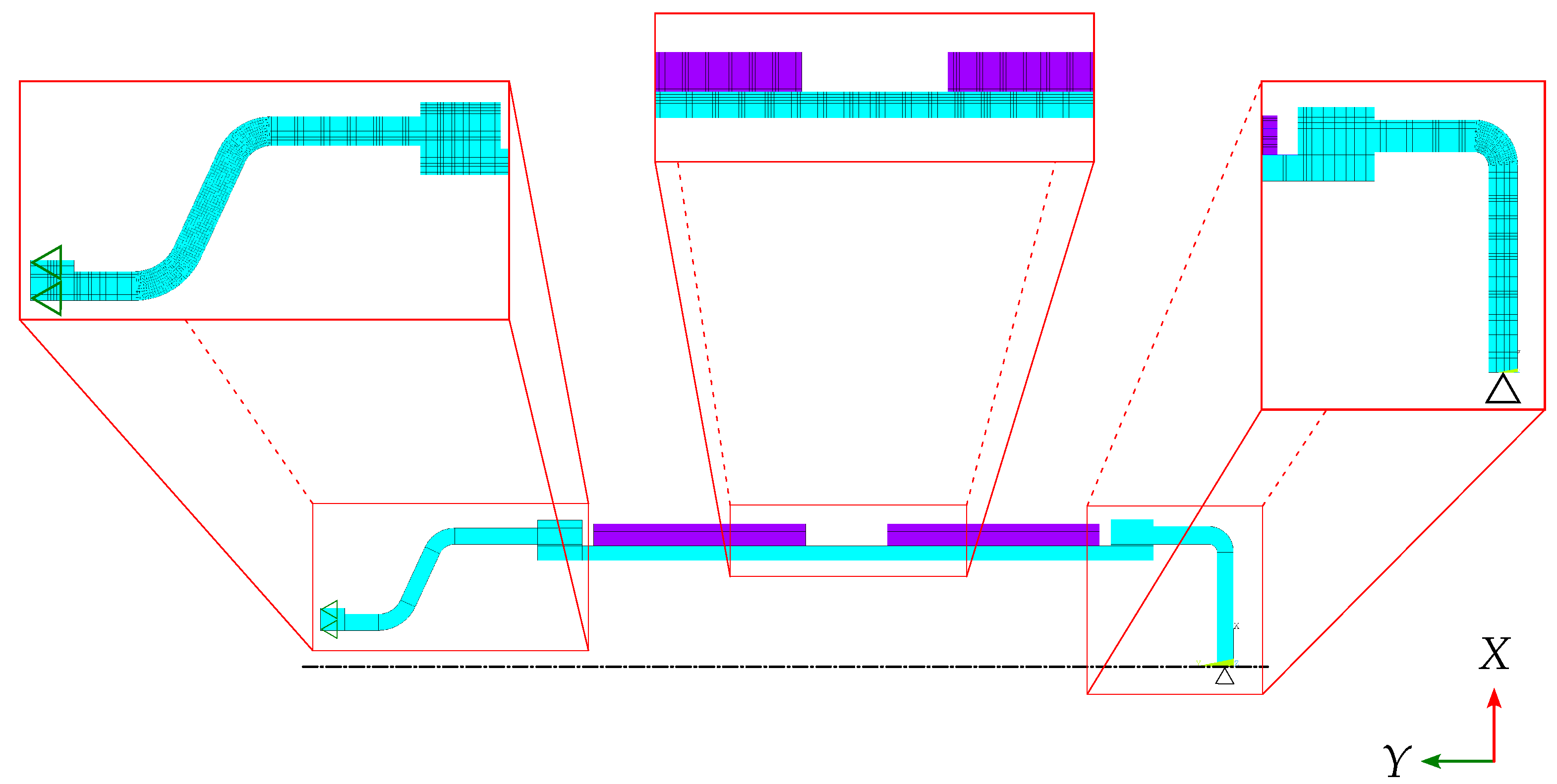
An axisymmetric finite element model was developed using the element PLANE183, which is an 8-node bidimensional element. The material of the steel wire reinforcement was modeled using the orthotropic equivalent properties reported by Celaya et al. [13], shown in Table 2. Each reinforcement layer was modeled as a separated region in contact with the adjacent surfaces. No detachment and friction between surfaces are considered to simulate their interaction. For illustration purposes, Figure 2 shows the two-dimensional mesh used to model the tank reinforced with three layers of wire. The mesh shown is the result of the mesh sensitivity analysis made, with a 0.1% maximum variation convergence criterion for the von Mises stress, and the results for this study are presented in Table 3. Regarding boundary conditions, a uniform internal pressure was applied to the inner surface of the vessel, and axial displacement was constrained by applying line supports at the vessel’s top (represented as green triangles in Figure 2).
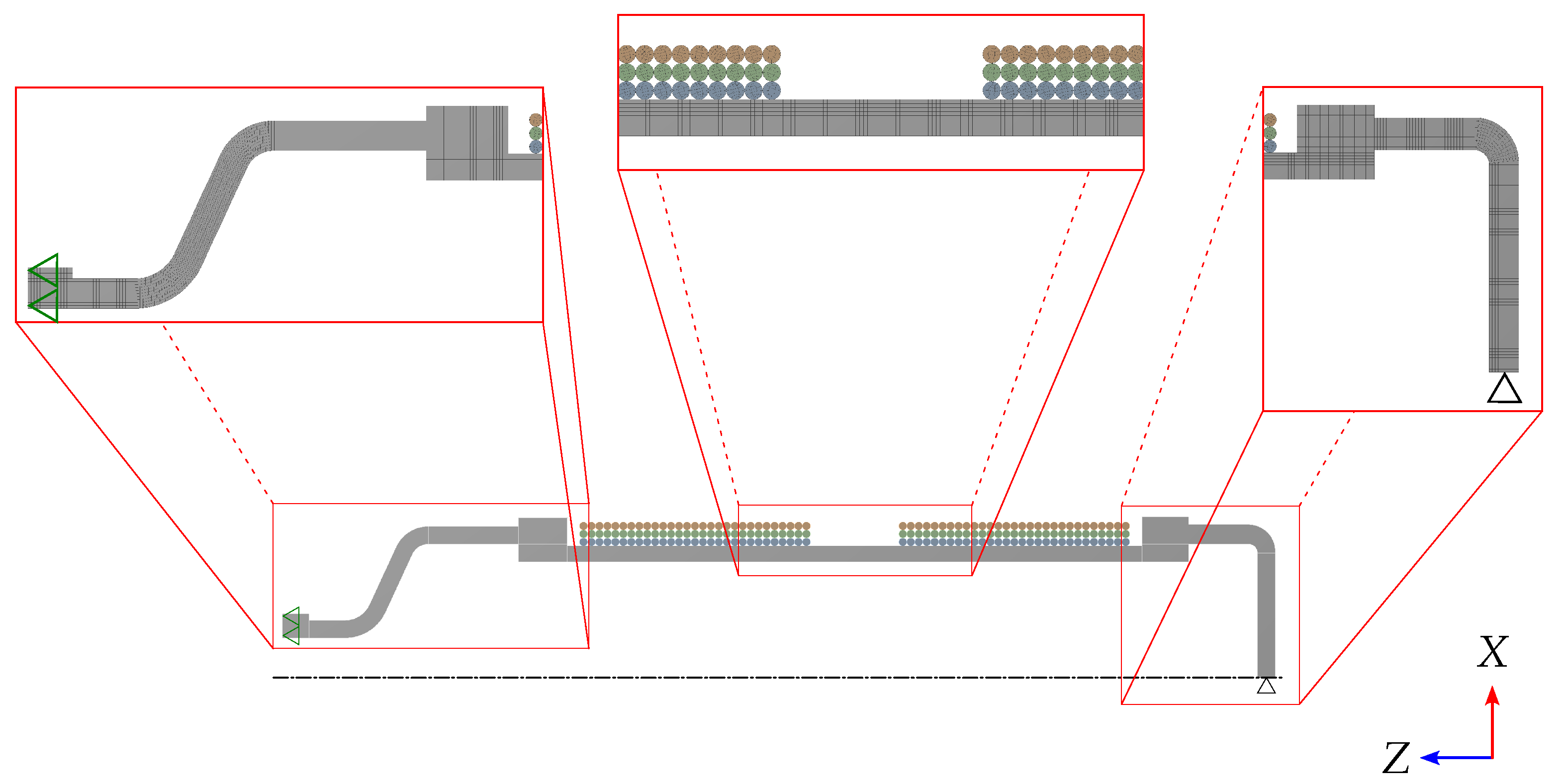
The solid model was developed using a 20-node solid element (SOLID186). In this case, symmetry was exploited, and only one degree of the whole geometry was modeled. The reinforcement was represented by cylinders that were in contact with each other and the tank. Contact elements were defined under the assumption of permanent bonding between surfaces, which prevents separation or relative sliding. Figure 3 shows the mesh used to model the tank reinforced with three layers of wire. Again, the mesh shown is the result of the mesh sensitivity analysis made, with a 0.1% maximum variation convergence criterion for the von Mises stress, and the results for this study are presented in Table 4. Even though the convergence is achieved earlier, compared with the plane model, the number of elements is more than double. Since solid elements are used, pressure boundary conditions were applied in the internal areas of the tank, while displacement at the top face of the tank was restricted in the Z-axis direction (see the green triangles in Figure 3). Finally, the mechanical properties of the reinforcement were taken from [13] and are presented in Table 5.

2.3. Prototype Fabrication

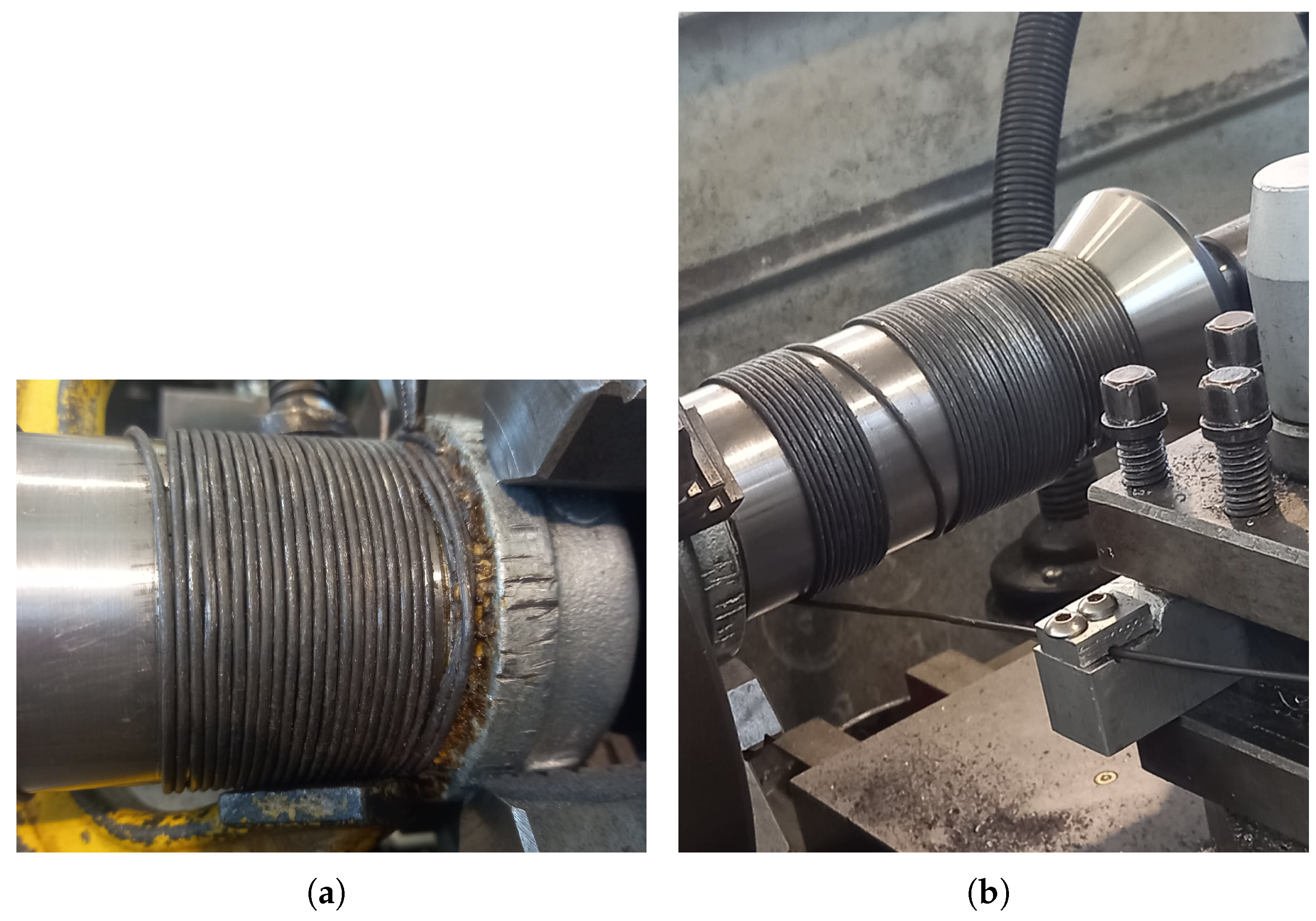
In order to validate the finite element model, small prototypes of metallic-reinforced pressure vessels were manufactured. The reinforcement is achieved by winding successive layers of steel wire around the cylindrical section; a layer of steel wire is partially shown in Figure 4a.
The fabrication began by welding the wire to the pipe nipple mounted on a conventional lathe. Then, the assembly was rotated at a low speed while the wire was stretched with constant tension, ensuring a uniform and controlled winding of the reinforcement layers around the pipe nipple (see Figure 4b). A central 2 cm wide region was deliberately left without reinforcement to allow for the placing of strain gauges, which will be used to measure the strains in the central region, to see the effect of the reinforcement in the cylindrical region and to validate the model. The fabrication process is completed by closing the ends of the reinforced pipe nipple, one with the bell reducer and the other with the threaded cap.
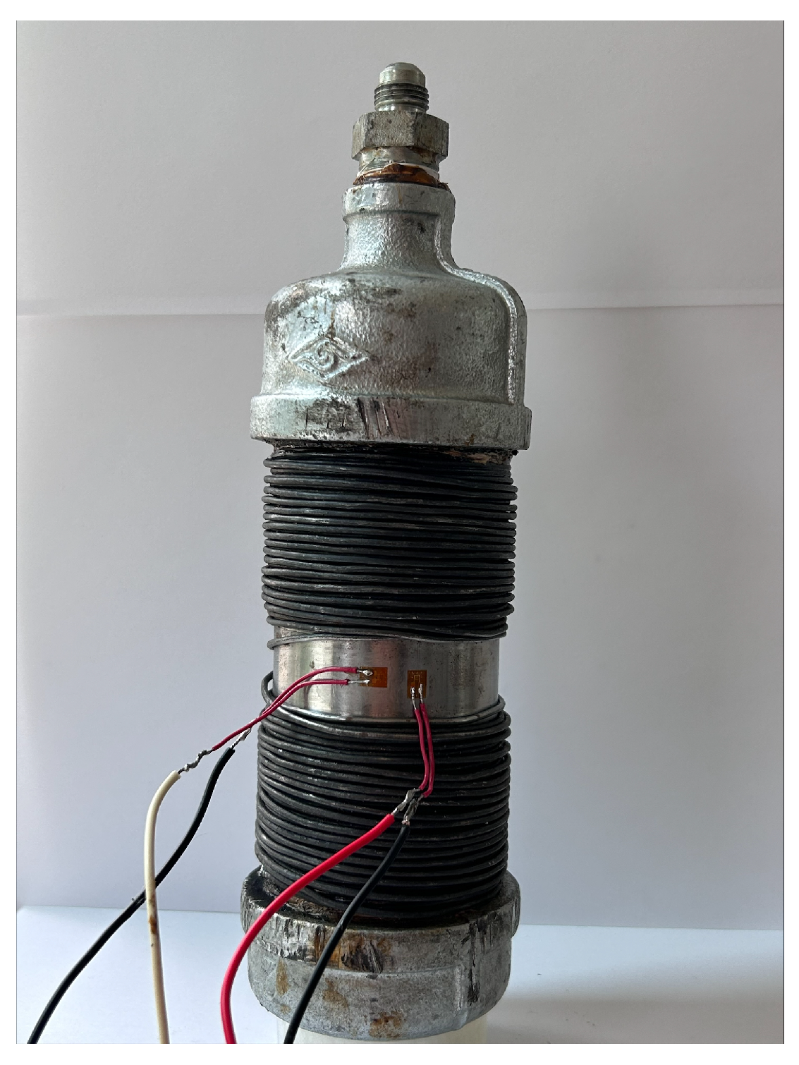
After finishing the manufacture of prototypes, they were instrumented by positioning strain gauges to measure both circumferential and axial strains. Figure 5 presents an instrumented prototype of a metallic-reinforced pressure vessel.

2.4. Experimental Setup

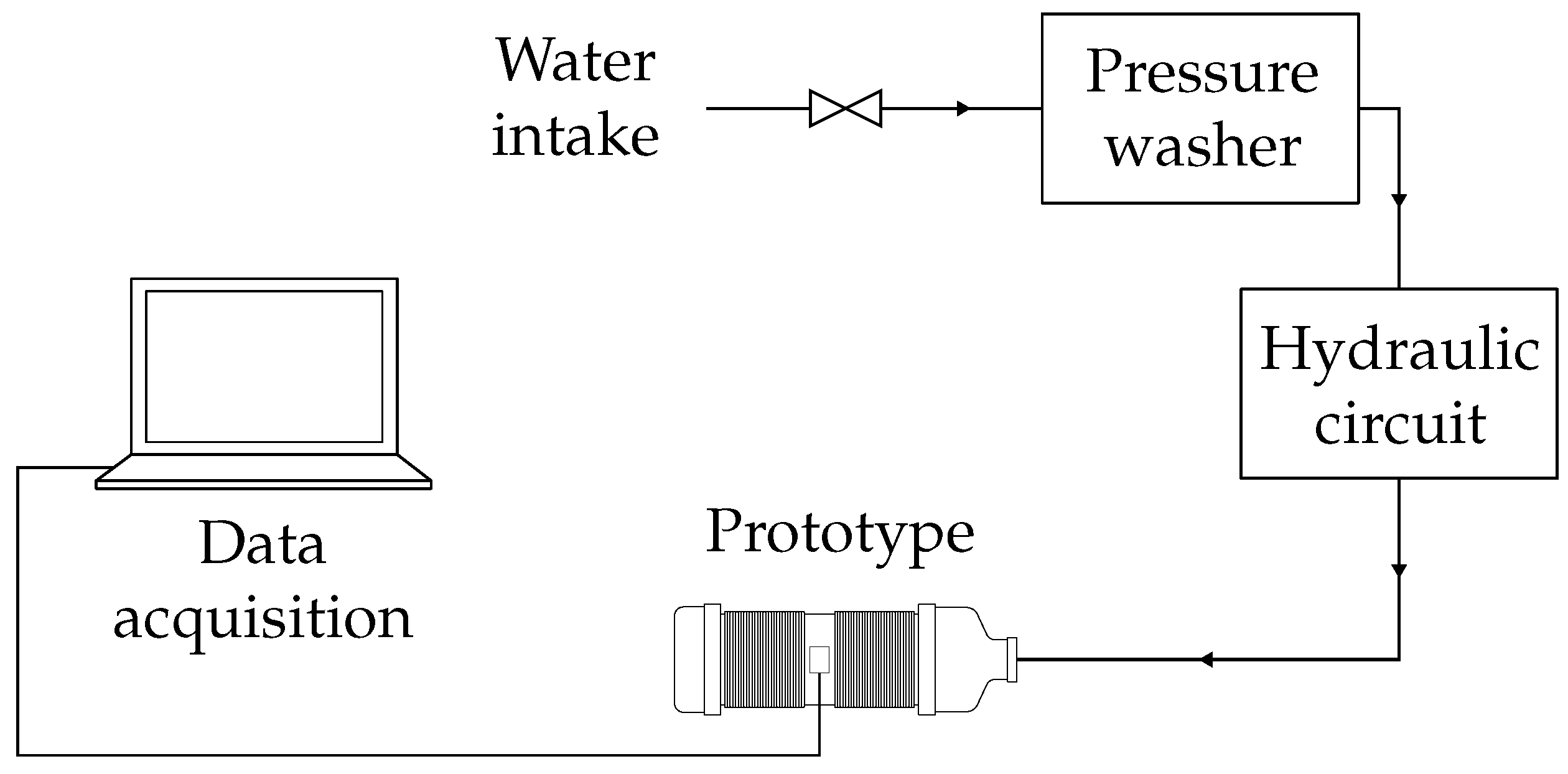
To validate the structural behavior of the present finite element model, the manufactured prototypes were subjected to pressure tests. For this purpose, a pressure washer with a maximum capacity of 5000 psi was used to generate the load. The pressure was regulated by means of a hydraulic circuit, which includes a control valve to maintain a specific pressure during testing, a pressure gauge, and a flow valve to regulate the water supplied to the system.
For safety reasons, the prototype was placed inside an empty cylindrical container during testing. The generated data during testing were collected by using a StudentDAQ MM01 data acquisition device from Micro-Measurement, optimized for 350 Ω strain gauges, and stored on a computer for subsequent analysis. Figure 6 shows an overview of the experimental setup.

2.5. Validation

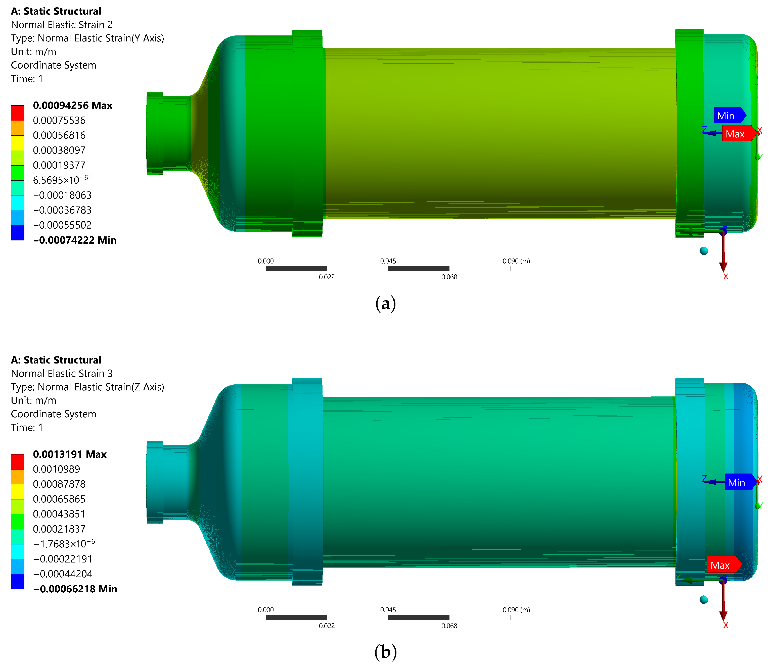
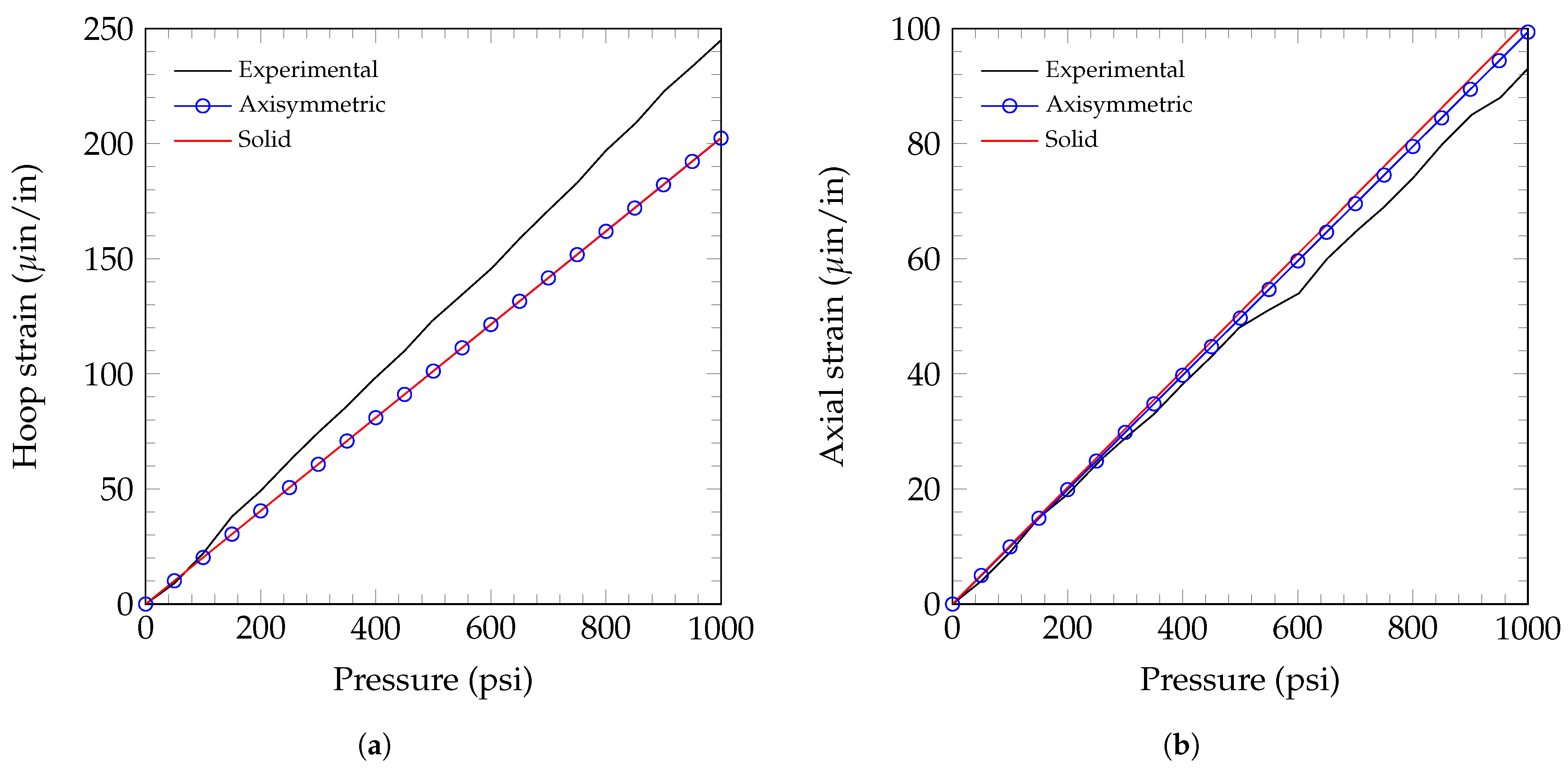
In order to validate the axisymmetric finite element model presented, a comparison was made between the numerical results obtained using solid elements and the experimental results. Also, to appreciate the influence of the reinforcement, a prototype without it was first tested and modeled. The results for the hoop and axial strains for this case are presented in Figure 7. An excellent agreement is noted for the hoop strain at the beginning of the test. However, after 500 psi, the numerical deformations start to differ from the experimental results, with a maximum relative error of 7%. On the other hand, for the axial strain, a slightly bigger difference is presented between the numerical results (which are almost identical) and the experimental results during all the comparisons, having a difference of 13% for the final load. Figure 8 presents the contours for the (a) hoop and (b) axial strains for the prototype without reinforcement at 1000 psi. It is worth noting that the strains are uniform in the cylindrical part of the prototype.
Figure 9 compares the experimental results and the finite element models for a prototype with one reinforcement layer for the hoop and axial strains. It is observed that the experimental hoop and axial strains are higher than those predicted for the finite element models, as the last two are almost identical. The difference between the experimental data and the finite element models, at the maximum applied pressure, is in the order of 12% and 13% for the hoop and axial strains, respectively.
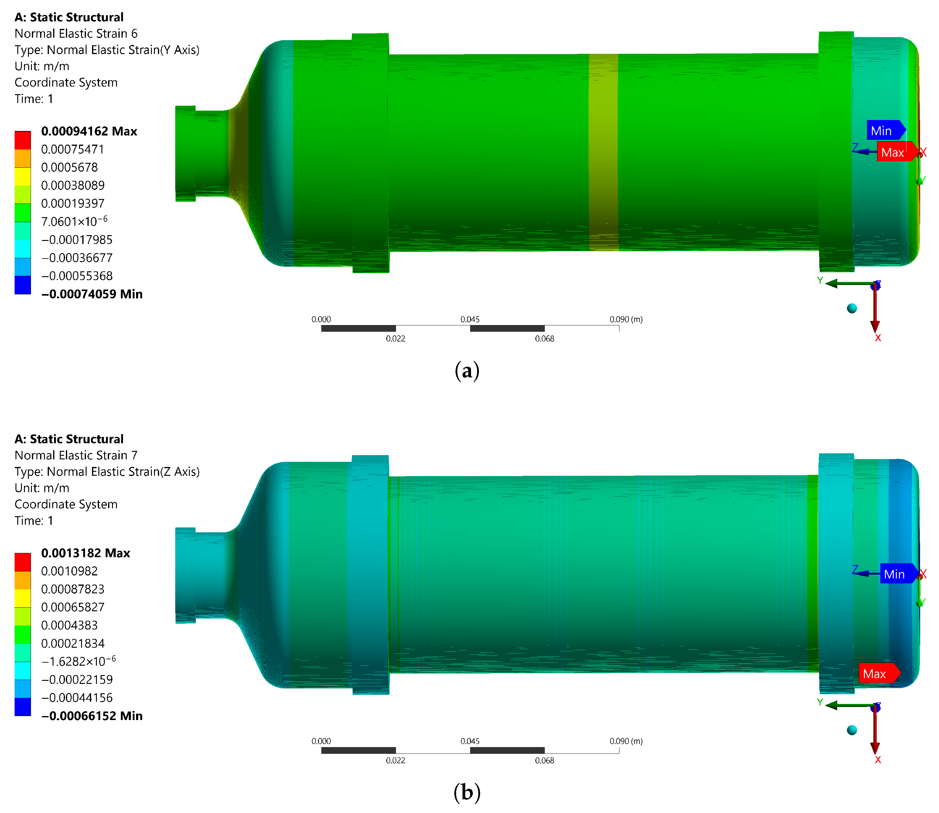
Finally, a comparison between the experimental results and the finite element models for the hoop and axial strains for a prototype with three layers of reinforcement is presented in Figure 10. For this case, the experimental hoop strains are higher than those predicted for the finite element models, while the axial strains are lower. The difference between the experimental data and the axisymmetric finite element model is 18% and 6% for the hoop and axial strains, respectively. Figure 11 presents the contours for the (a) hoop and (b) axial strains for the cylindrical part of the prototype with three layers of reinforcement at 1000 psi. Here, the effect of the reinforcement can be seen in the middle of the prototype, which has higher deformations since this part was left without reinforcement to place the strain gauges.

3. Numerical Analysis

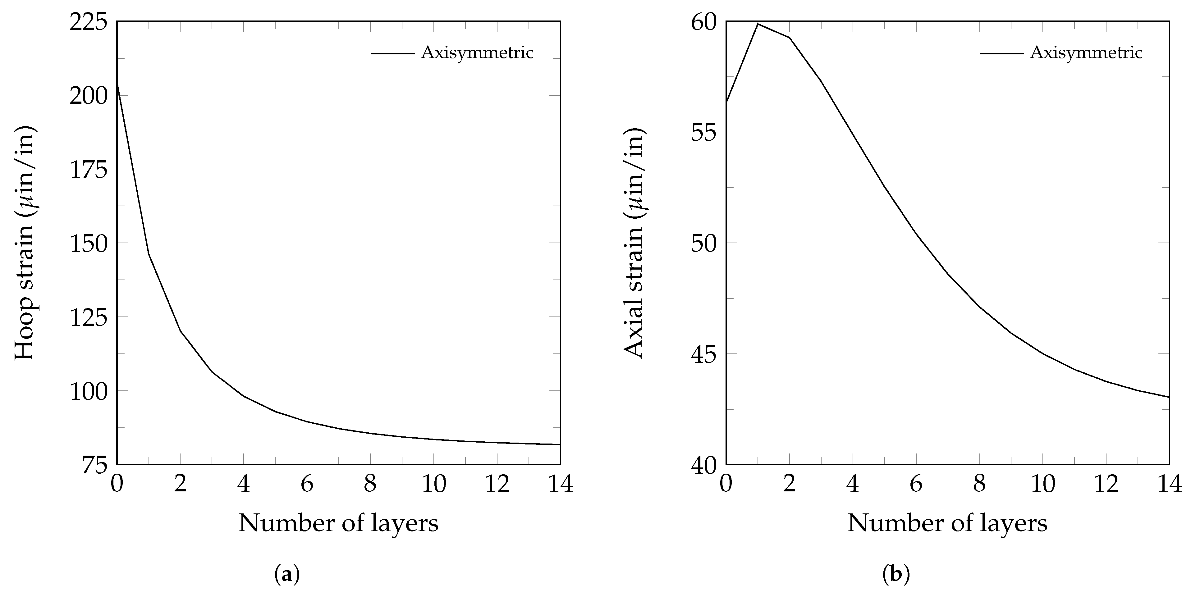
Since results from the solid and axisymmetric models are very close, but with considerably less computational effort used by the latter model, a study of the influence of the number of reinforcement layers on strain is performed using the axisymmetric model. Figure 12 shows the hoop and axial strains for different numbers of layers of reinforcement at 1000 psi. On the one hand, a significant reduction is observed for the hoop strain until five turns, decreasing from 204 μin/in to 93 μin/in, with differences higher than 5% between each layer increment. After that, the reduction is lower, with a difference between 13 and 14 layers of 0.33%. On the other hand, axial strains start increasing until two layers, reaching a maximum of 60 μin/in, and then decreasing slowly, having differences lower than 5%, and stabilizing at 0.70% between 13 and 14 layers.
For completeness, hoop and axial stresses are presented in Figure 13. It is observed that both stresses decrease when the number of layers is increased. For the first layer, the reductions in the hoop and axial stresses are in the order of 12.81 MPa and 3.04 MPa, respectively, compared to the model without reinforcement, while the mass increases by 290 g. For the case with 14 layers, the reductions of the stresses are 0.08 MPa in both directions, with respect to the model with 13 layers. However, the mass increases by 506 g for the same case.
Finally, Table 6 presents how the mass, the hoop, and axial stresses vary, with respect to the base model, when different numbers of layers of reinforcement are added. The mass added for each layer is higher than the previous one, while the stress reduction is lower. For example, from 1 to 2 layers, the mass increases by 19.44% and the hoop and axial stresses decrease by 12.51% and 7.86%. In comparison, from 13 to 14 layers, the mass increases by 33.98%, and the hoop and axial stresses only reduce by 0.17% and 0.36%, respectively. Based on these observations and the ASME Boiler and Pressure Vessel Code [29], it is recommended that the reinforcement has at least 10 layers. After that, the relative stress reduction should be monitored, and if it is lower than 1%, it is suggested that the number of layers should not be increased and the design should be tested. If it does not meet the requirements, another wire should be used as reinforcement.

4. Conclusions

This work presents an axisymmetric finite element model that can predict the mechanical response of a wire-reinforced pressure vessel (type II). This model uses equivalent properties and contact elements between layers to model the wire reinforcement. The proposed model showed very good agreement with the results obtained through solid elements and reasonable agreement with the experimental results. The latest difference in results is mainly attributed to errors inherent in the experimental work, such as variations in mechanical properties, inaccuracies in measurement devices, fluctuations in input pressure, dimensional deviations of the final parts due to the manufacturing process, and misalignment of the strain gauge.
Also, the numerical study showed that there is a limit to increasing the number of layers, which does not increase the vessel’s strength considerably but does increase its mass. Furthermore, the proposed model could be used in the optimization process in the early stages of the wire-reinforced pressure vessel type II design for hydrogen storage.
It is important to note that the present model only works when the geometry, loads, and boundary conditions are axisymmetric. This model should not be used if a load or boundary condition makes the problem asymmetric. Furthermore, it is worth mentioning that the manufacturing process for the reinforcement should be monitored and comply with the recommendations from the ASME Boiler and Pressure Vessel Code [29]. Specifically, the helix angle of the winding should be less than 1 degree, the maximum gap between wires in the longitudinal direction of the vessel should be less than 5% of the wire width, and neither the inner cylinder nor the wire should yield.

Author Contributions

Conceptualization, M.E.G.R. and E.R.L.O.; methodology, M.E.G.R. and A.L.L.R.; software, M.E.G.R. and A.L.L.R.; validation, M.E.G.R. and A.L.L.R.; formal analysis, M.E.G.R., A.L.L.R. and E.R.L.O.; investigation, M.E.G.R. and A.L.L.R.; writing—original draft preparation, M.E.G.R., A.L.L.R. and C.E.V.M.; writing—review and editing, M.E.G.R., E.R.L.O. and I.M.R.; visualization, A.L.L.R. and C.E.V.M.; supervision, M.E.G.R., E.R.L.O. and I.M.R.; project administration, M.E.G.R.; funding acquisition, M.E.G.R. All authors have read and agreed to the published version of the manuscript.

Funding

This research was funded by the University of Guanajuato, grant number CIIC 241/2024.

Data Availability Statement

The data presented in this study can be made available upon request from the corresponding author. The data are not publicly available.

Acknowledgments

The authors acknowledge the support of the University of Guanajuato for providing experimental, computational and software facilities. SECIHTI’s assistance with graduate student and senior researcher fellowships is also appreciated.

Conflicts of Interest

The authors declare no conflicts of interest.

References

  1. Cheng, Q.; Zhang, R.; Shi, Z.; Lin, J. Review of common hydrogen storage tanks and current manufacturing methods for aluminium alloy tank liners. Int. J. Lightweight Mater. Manuf. 2024, 7, 269–284. [Google Scholar] [CrossRef]
  2. Ahad, M.T.; Bhuiyan, M.M.H.; Sakib, A.N.; Becerril Corral, A.; Siddique, Z. An overview of challenges for the future of hydrogen. Materials 2023, 16, 6680. [Google Scholar] [CrossRef]
  3. Kadirgama, K.; Samylingam, L.; Aslfattahi, N.; Kiai, M.S.; Kok, C.K.; Yusaf, T. Advancements and challenges in numerical analysis of hydrogen energy storage methods: Techniques, applications, and future direction. Int. J. Hydrogen Energy 2025, 125, 67–85. [Google Scholar] [CrossRef]
  4. Ma, N.; Zhao, W.; Wang, W.; Li, X.; Zhou, H. Large scale of green hydrogen storage: Opportunities and challenges. Int. J. Hydrogen Energy 2024, 50, 379–396. [Google Scholar] [CrossRef]
  5. Abdalla, A.M.; Hossain, S.; Nisfindy, O.B.; Azad, A.T.; Dawood, M.; Azad, A.K. Hydrogen production, storage, transportation and key challenges with applications: A review. Energy Convers. Manag. 2018, 165, 602–627. [Google Scholar] [CrossRef]
  6. Nachtane, M.; Tarfaoui, M.; Abichou, M.A.; Vetcher, A.; Rouway, M.; Aâmir, A.; Mouadili, H.; Laaouidi, H.; Naanani, H. An overview of the recent advances in composite materials and artificial intelligence for hydrogen storage vessels design. J. Compos. Sci. 2023, 7, 119. [Google Scholar] [CrossRef]
  7. Batul, B.; Sohail, A.; Aizaz, A.; Jamil, Z. Application of structural similitude for scaling of a pressure vessel. In Proceedings of the IOP Conference Series: Materials Science and Engineering, Kuala Lumpur, Malaysia, 29–30 August 2019; IOP Publishing: Bristol, UK, 2019; Volume 642, p. 012004. [Google Scholar]
  8. Zhang, Q.; Xu, H.; Jia, X.; Zu, L.; Cheng, S.; Wang, H. Design of a 70 MPa type IV hydrogen storage vessel using accurate modeling techniques for dome thickness prediction. Compos. Struct. 2020, 236, 111915. [Google Scholar] [CrossRef]
  9. Kumar, S.S.; Bibin, C.; Ramachandran, M. Design and analysis of hydrogen storage tank with different materials by ansys. In Proceedings of the IOP Conference Series: Materials Science and Engineering, Mumbai, India, 23–24 December 2019; IOP Publishing: Bristol, UK, 2020; Volume 810, p. 012016. [Google Scholar]
  10. Kwak, H.S.; Park, G.Y.; Kim, C. Design of compressed natural gas pressure vessel (Type II) to improve storage efficiency and structural reliability. J. Press. Vessel Technol. 2020, 142, 011303. [Google Scholar] [CrossRef]
  11. Park, G.; Jang, H.; Kim, C. Design of composite layer and liner for structure safety of hydrogen pressure vessel (type 4). J. Mech. Sci. Technol. 2021, 35, 3507–3517. [Google Scholar] [CrossRef]
  12. Nguyen, B.N.; Roh, H.S.; Merkel, D.R.; Simmons, K.L. A predictive modeling tool for damage analysis and design of hydrogen storage composite pressure vessels. Int. J. Hydrogen Energy 2021, 46, 20573–20585. [Google Scholar] [CrossRef]
  13. Celaya Garcia, L.; Gutierrez Rivera, M.; Ledesma Orozco, E.; Aceves, S.M.; Martinez Ramirez, I. Equivalent properties of pure metallic reinforcement for pressure vessels using the finite element method. J. Braz. Soc. Mech. Sci. Eng. 2021, 43. [Google Scholar] [CrossRef]
  14. Błachut, A.; Wollmann, T.; Panek, M.; Vater, M.; Kaleta, J.; Detyna, J.; Hoschützky, S.; Gude, M. Influence of fiber tension during filament winding on the mechanical properties of composite pressure vessels. Compos. Struct. 2023, 304, 116337. [Google Scholar] [CrossRef]
  15. Wu, X.; Yang, B.; Zhou, S. Strength and Failure Analysis of Fiber-Wound Composite Gas Cylinder via Numerical Simulation. Materials 2024, 17, 717. [Google Scholar] [CrossRef]
  16. Azeem, M.; Hamdan, H.Y.; Alam, M.A.; Kumar, M.; Sajid, Z.; Gohery, S.; Maziz, A.; Gemi, L.; Abdullah, S.S.; Khan, S.H. Influence of winding angles on hoop stress in composite pressure vessels: Finite element analysis. Results Eng. 2024, 21, 101667. [Google Scholar] [CrossRef]
  17. Katsumata, S.; Ogasawara, T.; Uchino, T.; Hirayama, N.; Sakata, K.; Uzawa, K. Experimental and analytical study of a high-pressure hydrogen storage tank made of CFRP with dome–cylinder split molding structure for fuel cell vehicles. Int. J. Hydrogen Energy 2025, 101, 269–279. [Google Scholar] [CrossRef]
  18. Reda, R.; Ataya, S.; Ashraf, A. Finite Element Modeling of Different Types of Hydrogen Pressure Vessels Under Extreme Conditions for Space Applications. Processes 2025, 13, 1429. [Google Scholar] [CrossRef]
  19. Koutsawa, Y.; Bouhala, L. Uncertainty analysis in the design of Type-IV composite pressure vessels for hydrogen storage. Compos. Part C Open Access 2025, 16, 100544. [Google Scholar] [CrossRef]
  20. Syed, Z.A.H.; Che, J.l.; Chang, S.H. Design of a Type-III hydrogen pressure vessel with an elliptical dome for stress reduction in the composite layer. Int. J. Hydrogen Energy 2025, 103, 937–950. [Google Scholar] [CrossRef]
  21. Barthélémy, H.; Weber, M.; Barbier, F. Hydrogen storage: Recent improvements and industrial perspectives. Int. J. Hydrogen Energy 2017, 42, 7254–7262. [Google Scholar] [CrossRef]
  22. Hassan, I.; Ramadan, H.S.; Saleh, M.A.; Hissel, D. Hydrogen storage technologies for stationary and mobile applications: Review, analysis and perspectives. Renew. Sustain. Energy Rev. 2021, 149, 111311. [Google Scholar] [CrossRef]
  23. Wang, Z.; Wang, Y.; Afshan, S.; Hjalmarsson, J. A review of metallic tanks for H2 storage with a view to application in future green shipping. Int. J. Hydrogen Energy 2021, 46, 6151–6179. [Google Scholar] [CrossRef]
  24. Zhou, W.; Wang, J.; Pan, Z.B.; Liu, J.; Ma, L.H.; Zhou, J.Y.; Su, Y.F. Review on optimization design, failure analysis and non-destructive testing of composite hydrogen storage vessel. Int. J. Hydrogen Energy 2022, 47, 38862–38883. [Google Scholar] [CrossRef]
  25. Li, J.; Chai, X.; Gu, Y.; Zhang, P.; Yang, X.; Wen, Y.; Xu, Z.; Jiang, B.; Wang, J.; Jin, G.; et al. Small-scale high-pressure hydrogen storage vessels: A review. Materials 2024, 17, 721. [Google Scholar] [CrossRef] [PubMed]
  26. Bohorquez Rico, H.A. Diseño y Simulación de un Tanque Tipo II Revestido con Alambre de Acero SA-905. Master’s Thesis, Universidad de Guanajuato, Guanajuato, Mexico, 2018. Available online: http://repositorio.ugto.mx/handle/20.500.12059/392 (accessed on 19 June 2025).
  27. Saxena, A.; Prakash, A.; Sharp, G.; Thomson, W.; David, T.; Harless, F.; Vain, J.; Miller, I.; Nagpal, V.; Peters, D.T.; et al. Low Cost Hydrogen Storage at 875 Bar Using Steel Liners and Steel Wire Wraps; Technical report; WireTough Cylinders, LLC: Bristol, VA, USA, 2019. [Google Scholar]
  28. MatWeb, LLC. ASTM A36 Steel, Plate. 2025. Available online: https://www.matweb.com/search/DataSheet.aspx?MatGUID=afc003f4fb40465fa3df05129f0e88e6 (accessed on 26 June 2025).
  29. American Society of Mechanical Engineers. ASME Boiler and Pressure Vessel Code, 2021st ed.; ASME: New York, NY, USA, 2021. [Google Scholar]
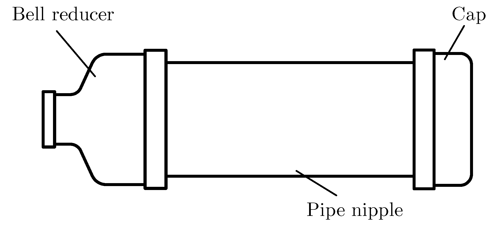
Figure 1. Schematic representation of prototypes.
Hydrogen 06 00055 g001
Figure 2. Axisymmetric mesh for a prototype with three layers of reinforcement.
Hydrogen 06 00055 g002
Figure 3. Solid mesh for a prototype with three layers of reinforcement.
Hydrogen 06 00055 g003
Figure 4. Prototype fabrication: (a) wire layer and (b) assembly.
Hydrogen 06 00055 g004
Figure 5. Prototype of a metallic-reinforced pressure vessel.
Hydrogen 06 00055 g005
Figure 6. Overview of the experimental setup.
Hydrogen 06 00055 g006
Figure 7. Internal pressure vs. (a) hoop and (b) axial strains for the prototype without reinforcement.
Hydrogen 06 00055 g007
Figure 8. Components of the strain for the prototype without reinforcement at 1000 psi: (a) Hoop. (b) Axial.
Hydrogen 06 00055 g008
Figure 9. Internal pressure vs. (a) hoop and (b) axial strains for the prototype with one layer of reinforcement.
Hydrogen 06 00055 g009
Figure 10. Internal pressure vs. (a) hoop and (b) axial strains for the prototype with three layers of reinforcement.
Hydrogen 06 00055 g010
Figure 11. Components of the strain in the cylindrical part of the prototype with three layers of reinforcement at 1000 psi: (a) Hoop. (b) Axial.
Hydrogen 06 00055 g011
Figure 12. Number of layers of reinforcement vs. (a) hoop and (b) axial strains for the prototype.
Hydrogen 06 00055 g012
Figure 13. Number of layers of reinforcement vs. (a) hoop and (b) axial stresses for the prototype.
Hydrogen 06 00055 g013
Table 1. Mechanical properties of ASTM A36 steel [28].
Mechanical PropertyValueUnits
Modulus of elasticity200GPa
Poisson’s ratio0.26-
Table 2. Equivalent mechanical properties for the steel wire reinforcement [13].
Mechanical PropertyValueUnits
Elastic modulus E x 160.0GPa
Elastic modulus E y 21.0GPa
Elastic modulus E z 21.0GPa
Shear modulus G x y 26.2GPa
Shear modulus G x z 26.2GPa
Shear modulus G y z 25.4GPa
Poisson’s ratio ν x y 0.16-
Poisson’s ratio ν x z 0.16-
Poisson’s ratio ν y z 0.07-
Table 3. Mesh independence study for the axisymmetric model.
Iterationvon Mises Stress (MPa)ChangeNodesElements
141.973 725146
242.3380.94%2241530
342.568−0.11%71991978
442.5660.16%11,3943271
542.654−0.33%25,3887633
642.706−0.14%29,3388861
742.7090.04%37,59211,497
Table 4. Mesh independence study for the solid model.
Iterationvon Mises Stress (MPa)ChangeNodesElements
142.875 43,0906220
242.611−0.92%48,9387212
342.670−0.35%68,34910,888
442.629−0.15%82,66913,696
542.644−0.05%140,86825,340
Table 5. Mechanical properties of the steel wire [13].
Mechanical PropertyValueUnits
Modulus of elasticity200GPa
Poisson’s ratio0.3-
Table 6. Percentage of mass increase and stress reduction for layers of reinforcement with respect to the base model.
Layers% of Mass Added% of Hoop Stress Reduction% of Axial Stress Reduction
118.227.313.0
237.739.820.8
358.346.726.6
480.250.931.1
5103.353.734.7
6127.655.637.6
7153.156.940.0
8179.857.941.8
9207.758.643.2
10236.859.144.3
11267.259.545.1
12298.759.845.8
13331.560.046.2
14365.560.246.6
Disclaimer/Publisher’s Note: The statements, opinions and data contained in all publications are solely those of the individual author(s) and contributor(s) and not of MDPI and/or the editor(s). MDPI and/or the editor(s) disclaim responsibility for any injury to people or property resulting from any ideas, methods, instructions or products referred to in the content.