Article

Parametric Study and Design of a Novel Bolted Endplate Rigid Connection Between CCFT Columns and Wide-Flange Beams


1
School of Civil Engineering and Architecture, Taizhou University, Taizhou 318000, China
2
College of Urban Construction, Zhejiang Shuren University, Hangzhou 310015, China
3
School of Civil Engineering, Southwest Jiaotong University, Chengdu 610031, China
*
Author to whom correspondence should be addressed.
Eng 2026, 7(4), 158; https://doi.org/10.3390/eng7040158
Submission received: 14 January 2026 / Revised: 13 March 2026 / Accepted: 26 March 2026 / Published: 1 April 2026
(This article belongs to the Section Chemical, Civil and Environmental Engineering)

Abstract

This study proposes a design method for a novel bolted endplate rigid connection between circular concrete-filled steel tube (CCFT) columns and wide-flange (WF) steel beams, with particular emphasis on the parametric behavior governing joint performance. Based on the preliminary quasi-static tests, finite element simulations are conducted to evaluate the flexural behavior and failure mechanisms under beam-end maximum moment, followed by an extensive parametric study examining the effects of square tube dimensions, high-strength grout, and column axial load. The numerical results show that the wall thickness of the square steel tube significantly affects grout indentation. A 60% reduction in wall thickness led to a 503% increase in indentation. In contrast, variations in tube dimensions, grout strength, and column axial load within the studied range caused less than a 16% change and did not influence the flexural performance. These results indicate that the constraints on tube dimensions and axial load may be relaxed. The proposed connection effectively overcomes the limitations of conventional CCFT-to-beam joints, including unfavorable stress transfer, complex detailing, and construction inefficiency, by modifying the load-transfer mechanism and reducing the demand on tensile-critical welds, thereby enhancing ductility. Based on the parametric findings, a design method is established, and theoretical analysis confirms that the proposed connection satisfies the stiffness requirements for fully rigid connections. Future quasi-static tests with different member sizes are recommended to validate these findings.

1. Introduction

Compared with conventional reinforced concrete frame columns and concrete-filled steel tube columns with other cross-sectional shapes, circular concrete-filled steel tube (CCFT) columns have been shown to provide favorable seismic performance. Previous studies have reported that CCFT columns achieve efficient composite action between steel and concrete, relatively high axial compressive and flexural strength-to-weight ratios, uniform bending behavior, adequate ductility, stable hysteretic response, satisfactory fire performance, and cost efficiency [1,2,3,4,5,6,7]. As a result, CCFT columns are commonly adopted in seismic design due to their contribution to the overall seismic capacity of frame structures. In addition, the elimination of external formwork for concrete casting simplifies construction and reduces construction time and cost.
However, the closed cross-section and curved surface of CCFT columns complicate the formation of connections with conventional WF steel beams. Studies over the past three decades have indicated that such connections, when inadequately detailed, generally exhibit unsatisfactory seismic performance [8,9,10]. The most straightforward approach involves directly welding the beam to the exterior surface of the circular steel tube. This configuration imposes high demands on the radial stiffness of the tube wall and is susceptible to tube wall tearing and brittle weld failure [11,12]. An alternative approach uses curved beam endplates fastened to the tube wall with blind bolts or fasteners [13,14,15]. When the tube wall thickness is insufficient, premature local buckling of the tube wall may occur under column axial load [15], making it difficult to satisfy the stiffness requirements of fully rigid connections [16]. The use of external ring plates can increase the radial stiffness of the tube wall; however, this measure has been reported to cause earlier degradation of joint flexural capacity and brittle weld failure [8,17]. Although increasing the size of the external ring plate can improve seismic performance [18], it may interfere with the arrangement of curtain wall systems at the joint region [11].
The use of internal ring plates, through plates, or embedded shear studs has been shown to enhance the radial stiffness of the tube wall while limiting the overall joint size [17,19,20,21]. Alternatively, beam flange forces may be transferred directly to the core concrete by means of through-beam flanges or by passing the entire beam cross-section through the column [22,23,24]. Similar force-transfer mechanisms can also be achieved by welding embedded reinforcing bars to beam flanges or by welding hooked reinforcing bars to the inner surface of the steel tube [25]. Although these approaches can improve joint seismic behavior, they generally require extensive cutting and re-welding of the circular steel tube during assembly. Such operations may compromise the integrity of the steel tube, introduce complex welding residual stresses, increase the likelihood of brittle joint failure, and hinder post-earthquake repair. In addition, the use of internal components raises concerns regarding adequate compaction of the core concrete during casting [17]. Moreover, joint configurations employing curved endplates tend to limit the size of the connected steel beams [26] and may induce additional horizontal moments and shear forces at the ends of high-strength bolts. In contrast, existing connection forms employing flat endplates cannot be extended to bidirectional moment-resisting joints due to welding space limitations [27]. The features and limitations of existing joint configurations have been discussed in detail in the authors’ previous studies [28].
This study presents a joint design method intended to achieve rigid connections between CCFT columns and WF steel beams. The proposed joint addresses several limitations reported for existing connection types, including unfavorable force-transfer mechanisms, complex fabrication, restrictions on beam dimensions, difficulties in concrete casting, and limited reparability after damage [28]. Consequently, the proposed connection provides a practical solution for integrating CCFT columns into moment-resisting frame structures and contributes to improved seismic performance of frame structures in high seismic regions.

2. Design Principle

Brittle fracture of welds has been identified as a primary cause of collapse in steel structures during earthquakes [29,30,31]. Optimization of the load-transfer path within the connection can reduce the demand for tensile-critical welds, thus lowering the risk of brittle weld failure. In addition, factory prefabrication contributes to improved consistency and quality control of welds.
As illustrated in Figure 1, the proposed joint features a circular steel tube enclosed by an external square steel tube. The annular space between the two tubes is filled with high-strength grout, forming a flat bearing surface for the beam endplate. High-strength bolts pass through the entire column section, transferring the tensile force in the beam tension flange to the opposite side of the column in the form of compressive force. Under beam-end moments, the only primary tensile-critical weld is the full-penetration weld connecting the beam to the endplate. The beam-end shear force is transferred to the exterior surface of the circular steel tube via vertical shear welds along the vertical stiffeners.
This configuration effectively prevents radial tension in the circular steel tube wall. Its primary advantage lies in the optimized force-transfer path, which limits the main tensile component and tensile weld to a single load-resisting element—namely, the high-strength bolts and the full-penetration weld connecting the beam to the endplate. By eliminating critical components subjected to cyclic tension–compression under seismic loading and avoiding on-site welding, the risks of local fracture and fatigue failure are significantly reduced. All welding and grout-filling steps are carried out in the factory, while only the casting of core concrete and installation of high-strength bolts are required on site, thereby substantially improving construction quality and efficiency.
All primary load-carrying components of the proposed joint are able to effectively utilize their respective material advantages, resulting in a clear and well-defined force-transfer mechanism, as summarized below.
(1)
Tensile force in the beam flange: beam tension flange → full-penetration weld → beam endplate → high-strength bolts → square steel tube wall on the opposite side of the column → infilled high-strength grout → CCFT column.
(2)
Compressive force in the beam flange: beam compression flange → full-penetration weld → beam endplate → square steel tube wall → infilled high-strength grout → CCFT column.
(3)
Shear force: beam → full-penetration weld → beam endplate → high-strength bolts → square steel tube and infilled high-strength grout → vertical stiffeners → CCFT column.
These load-transfer mechanisms indicate that the infilled high-strength grout plays a critical role in all force-transfer paths.
Endplate bolted steel connections are widely considered among the most reliable joint configurations for seismic resistance. The primary distinction between such conventional connections and the proposed joint lies in the support mechanism for the endplate. In the proposed joint, the beam endplate bears against the high-strength grout infilled between the two steel tubes. Consequently, the mechanical properties and failure modes of the high-strength grout are expected to play a governing role in determining whether the proposed joint can achieve the intended flexural performance. Accordingly, the performance and failure mechanism of the high-strength grout are investigated in this study as an important basis for joint design.

3. Design Method

3.1. Endplate and High-Strength Bolts

The primary difference between the proposed joint and conventional endplate bolted steel connections lies in the support mechanism of the beam endplate, whereas the force-transfer principles of the endplate and high-strength bolts remain consistent with those of conventional connections. First, the design capacity of the joint is determined based on the seismic design philosophy of “strong column–weak beam and strong joint–weak member”. Subsequently, it is assumed that the rotation center of the endplate under beam-end moment coincides with the centroidal axis of the beam compression flange, based on which the required bolt diameter is calculated. Finally, the thickness of the endplate is determined using yield-line theory. Detailed calculation procedures can be found in ANSI/AISC 358-22 [32] and ANSI/AISC 341-16 [33].

3.2. High-Strength Grout

3.2.1. Strength

Under beam-end moments, the compressive force in the beam compression flange is transferred to the high-strength grout through the endplate and the square steel tube wall. With the assistance of flange stiffeners, the endplate distributes the compressive force from the beam flange into the high-strength grout, effectively enlarging the compression zone. Based on the assumed rotation center of the endplate, the compressive stress imposed on the high-strength grout by the endplate can be calculated as follows:
f g , e p = M f / d t b f A c
According to ACI 318 [34], when the bearing surface is larger than the applied load area in all directions, the compressive strength of the high-strength grout can be adjusted using a reduction factor, γ. Therefore, the axial compressive strength of the high-strength grout, F g , r e q , should satisfy the following relationship:
· γ · F g , r e q f g , e p
where A c = b p × h c , with b p being the width of the endplate and h c the distance from the centroid of the beam compression flange to the nearest edge of the endplate; M f is the maximum moment at the square steel tube wall; d is the beam depth; t b f is the flange thickness; γ = 0.85 A 2 / A 1 1.7 , where A 1 is the area of the applied load and A 2 is the bearing surface area; and is the strength reduction factor, which can be taken as 1.0. Since the high-strength grout is cast from the square steel tube’s upper cap plate, it adheres closely to the tube wall under self-weight, with no weak layer formed due to bleeding. Moreover, the load is transmitted indirectly to the grout through the square steel tube wall. Therefore, = 1.0 is adopted.

3.2.2. Stiffness

The tensile force in the beam tension flange is transmitted to the opposite side of the column through high-strength bolts and is applied via the bolt nuts onto the square steel tube wall and the high-strength grout. The compression area is defined by the contact area between the nut and the square steel tube wall. The load-transfer model for the bolt group is illustrated in Figure 2. Accordingly, the compressive stress imposed on the high-strength grout by the bolt nuts can be expressed as:
f g , b = P f 1 A n n , w h e r e   P f 1 = M f h 1 n b ( h 1 2 + h 2 2 )
Due to the relatively small contact area between the nut and the square steel tube, the high-strength grout is subjected to locally high compressive stress, resulting in compression deformation. Based on the configuration of the proposed joint, the distance from the nut to the edges of the high-strength grout is large relative to the nut size. Under confinement, the grout at the nut location is subjected to a triaxial stress state, exhibiting enhanced compressive strength. The compression deformation causes rigid-body displacement of the high-strength bolt along the shank and induces joint rotation, denoted as θ g r t . For typical steel frame structures, the interstory drift angle under seismic loading is limited to 2% [33]. In this study, the rotational limit of the proposed joint due to grout compression is set to 1/10 of the interstory drift angle limit, i.e.:
θ g r t = P f 1 t g A n n E g h 1 0.002
where P f 1 is the maximum tensile force in a single bolt under the beam-end moment M f ; n b is the number of bolts per row; A n n is the contact area between a single bolt nut and the square steel tube wall; E g is the stiffness of the high-strength grout; t g is the average grout thickness at the bolt hole; and h 1 and h 2 are the distances from the center of the tension bolts to the centroidal axis of the beam compression flange.

3.3. Square Steel Tube

As the bearing surface for the beam endplate, the minimum dimensions of the square steel tube should exceed those of the endplate, and its width must satisfy the construction requirements for casting high-strength grout between the two steel tubes. In this design method, a minimum edge distance of 25 mm from the beam endplate to the square steel tube edge is recommended. For a given circular concrete-filled steel tube column, the dimensions of the square steel tube uniquely determine the size of the infilled high-strength grout. In this study, finite element parametric analyses are conducted to investigate the influence of square steel tube dimensions on the performance of the high-strength grout.

3.4. Stiffeners and Other Components

The design of beam flange stiffeners and associated welds can be referred to in ANSI/AISC 358-22 [32]. Vertical stiffeners on the cap plates of the square steel tube are used to transfer the beam-end shear force. It is assumed that the four vertical stiffeners on the same side as the beam evenly share the beam-end shear. The vertical stiffeners are positioned within the radial plane of the circular steel tube, with their width extending to the corners of the square steel tube, while other dimensions follow the design approach of beam flange stiffeners. The square steel tube’s upper and lower cap plates are welded to the two steel tubes, with a width-to-thickness ratio not exceeding 60. Except for the full-penetration welds connecting the beam to the endplate, which undergo significant tensile forces, the remaining welds experience relatively low forces and need only satisfy minimum weld size requirements.

3.5. Prestress of High-Strength Bolts

The proposed joint employs through-type long bolts, whose elongation can reduce joint stiffness. The application of an appropriate prestress can fully compensate for this effect. The bolts transfer the beam-end shear through their bearing capacity. High-strength bolts are subjected to both beam-end moments and shear forces. According to GB 50017 [35], the tensile stress f b and shear stress f v in the bolts satisfy the following relationship:
( f b F y b ) 2 + ( f v F v b ) 2 1.0    
As the beam-end moment develops, the tensile stress in the high-strength bolts should satisfy the following condition:
f b η   F y b ,   w h e r e     η   = 1 ( f v F v b ) 2 < 1.0
Neglecting the self-weight of the members, it is assumed that under seismic loading, the shear force V h generated by simultaneous yielding of plastic hinges at both ends of the beam is uniformly resisted by all bolts. At this condition, the bending moment of the beam plastic hinge is M h , and the corresponding shear stress in the bolts, f v , can be expressed as:
f v = V h N b A n b , w h e r e       V h = 2 M h L n
Then
η = 1 ( 2 M h L n N b A n b F v b ) 2 < 1.0
The yield strength and yield strain of the high-strength bolts are denoted as F y b and ε y b , respectively. When the beam-end plastic hinge moment reaches M h , the maximum tensile stress in the bolts attains β F y b . Under a prestress of ρ F y b , the elongation of the high-strength bolts can be approximated as:
L b L b β ρ ε y b 0 , w h e r e       β η
Based on the bolt group load-transfer model illustrated in Figure 2, the rotation of the beam endplate induced by bolt elongation can be expressed as:
θ = L b h 1 L b β ρ h 1 ε y b 0
According to GB 50017 [35], the yield strength of grade 10.9S high-strength bolts is defined as the stress corresponding to a residual strain of 0.2%. Therefore, the strain at the yield strength can be expressed as:
ε y b = 0.002 + F y b / E b
Finally, under the beam-end moment, the rotation of the beam endplate induced by the tensile elongation of the bolts can be expressed as:
θ = L b β ρ h 1 × 0.002 + F y b E b 0 , w h e r e   β η
where F y b is bolt yield strength; F v b is bolt shear strength; ε y b is bolt yield strain; L b is original bolt length; ρ is bolt pretension ratio; β is bolt tensile stress to yield strength ratio; E b is bolt elastic modulus; N b is the number of bolts; A n b is one bolt net area; L n is distance between both plastic hinges on beam ends.
From the above equations, it can be seen that when the prestress satisfies ρ β , the high-strength bolts do not undergo elongation under the beam-end plastic hinge moment M h and thus have no impact on the rotational stiffness of the joint.

4. Benchmark Connection

Based on the aforementioned design method, a benchmark joint was developed for finite element analysis, using an exterior column joint on a middle-story of a three-bay, five-story moment-resisting frame with a story height of 3.5 m and a column spacing of 5 m as the prototype. The design method was then refined or supplemented based on the analysis results. The properties of this benchmark joint are consistent with those of the joints tested in the authors’ previous experiments [28], as shown in Figure 3 and Table 1 and Table 2.
Q235 steel was used for all steel components except the high-strength bolts. The material has nominal yield and ultimate tensile strengths of 235 MPa and 370 MPa, respectively, and a design yield strength of 215 MPa. The beam section was HN450 × 200 × 9 × 14, with a depth of 450 mm, a flange width of 200 mm, a web thickness of 9 mm, and a flange thickness of 14 mm. To meet the strong-column–weak-beam requirement, the CCFT column was designed with an outer diameter of 406 mm and a tube thickness of 10 mm. The beam endplate had dimensions of 770 mm × 240 mm × 30 mm. M30 × 600 grade 10.9S high-strength bolts were adopted, with a shank diameter of 30 mm and an effective threaded area of 5.61 cm2. The bolts provided a yield strength of 940 MPa at 0.2% residual strain and an ultimate tensile strength of 1040 MPa [35]. The upper cap plate of the square steel tube is provided with a grout injection hole and a vent hole for casting the high-strength grout, each with a diameter no less than 60 mm. Based on this construction requirement, the minimum width of the square steel tube is 520 mm, with a wall thickness equal to that of the circular steel tube. According to ANSI/AISC 358-22 [32], the thickness of the beam flange stiffeners is 10 mm. The square steel tube’s upper and lower cap plates have a thickness of 20 mm, with the vertical stiffeners on the cap plates also 10 mm thick. The grades of the core concrete and high-strength grout are C40 and C35, with standard axial compressive strengths of 26.8 MPa and 23.4 MPa, respectively. The actual material properties of each component were determined through experimental tests.
Except for the full-penetration welds connecting the beam to the endplate, which resist the significant tensile forces in the beam flanges, all other welds in the proposed joint are fillet welds with a leg size of 8 mm. The fillet welds primarily transfer loads through compression and shear, substantially reducing the likelihood of brittle failure. The welding electrodes used are of type J422, with a minimum tensile strength of 430 MPa, and welding is performed using the gas-shielded arc welding method. The joint dimensions and material strengths are detailed in Figure 3 and Table 1.
The binder system consisted of 42.5-grade ordinary Portland cement, Class I fly ash complying with GB/T 1596-2005 [36], and silica fume meeting the requirements of GB/T 21236-2007 [37]. The silica fume had a specific surface area of 1.5 × 10 5   c m 2 / g and contained at least 96% SiO2. Crushed stone with particle sizes of 10–30 mm was used as coarse aggregate, whereas medium river sand (0–5 mm) served as the fine aggregate. A polycarboxylate-based superplasticizer manufactured by ShanXi FeiKe Company (Changzhi, China) was incorporated in the mixtures. The mix proportions of the concrete and high-strength grout are listed in Table 2.

5. Finite Element Analysis

Finite element analyses were conducted using ABAQUS (2020) to investigate the stress states and failure modes of each component in the proposed joint under the beam-end ultimate moment. High-strength grout, as the primary focus of this study, is mainly influenced by the grout strength, the wall thickness of the square steel tube, and the height and width of the square steel tube. The grout strength directly governs the load-bearing capacity and stiffness. The wall thickness of the square steel tube affects both the bearing capacity of the grout surface and the confining effect on the grout. With the dimensions of the circular concrete-filled steel tube fixed, the height and width of the square steel tube solely determine the dimensions of the high-strength grout. Parametric studies were executed to quantify the influence of these factors on the grout performance, providing a basis for design. In addition, the effect of column axial load on joint performance was also examined.

5.1. FEA Models

5.1.1. Benchmark Model

A finite element model of a beam–column joint was established in ABAQUS, as shown in Figure 4. The column had a height of 3.5 m. Its centerline was positioned 2.5 m from the beam free end, while the beam centerline corresponded to the column mid-height. Detailed dimensions of all components are provided in Figure 3 and Table 1. To minimize computational cost, the web mid-plane of the beam was used as a plane of symmetry, and a half-joint model was adopted for the analysis.
As this study primarily focuses on the global flexural performance and load transfer mechanism of the connection, particularly the mechanical behavior of the high-strength grout, rather than the detailed through-thickness stress distribution of thin-walled steel components, a combined solid–shell modeling strategy was adopted. The grout, core concrete, and bolts were modeled using solid elements (C3D8R) to capture their three-dimensional behavior and damage evolution, while the remaining steel components, including the steel tubes and the beam—typical thin-walled members—were modeled using shell elements (S4R). For thin-walled steel components, shell elements can accurately represent membrane and bending behavior with high computational efficiency. The modeling approach has also been validated against previous quasi-static test results, confirming its ability to predict the overall strength and stiffness of the connection. The element size was kept below 40 mm to satisfy mesh sensitivity requirements. The composition of the model and the mesh distribution of each component are illustrated in Figure 5.
Neglecting weld failure, connected components were joined using the Merge method, including the beam–endplate–flange stiffener assembly and the circular-to-square steel tube–vertical stiffener assembly. For certain components, compressive and frictional forces are transferred through mutual contact, and relative sliding may occur; when the compressive force vanishes, these components are free to separate. Such interactions primarily exist between the square steel tube wall and the endplate, the high-strength bolts and surrounding components (including the square and circular steel tubes, high-strength grout, and core concrete), and between the bolt nuts and the square steel tube wall. These interactions were modeled using Surface-to-Surface or Surface-to-Line contact definitions, with the normal stiffness of the contact surfaces set sufficiently high to prevent penetration of one component into another. Friction coefficients of 0.3 and 0.45 were assigned to steel–steel and concrete–steel contacts, respectively. Since separation is allowed between the bolt nuts and the square steel tube wall, the nuts and endplate were tied using a Tie constraint to enforce coordinated movement. To facilitate the assessment of separation between the high-strength grout or core concrete and surrounding steel components based on the damage state of the concrete or grout surfaces, the core concrete and high-strength grout were also tied to the surrounding steel components using Tie constraints. Gaps were introduced between the stiffeners and the beam flanges or cap plates to account for flange and cap plate thicknesses, after which Tie constraints were applied to bind the stiffeners to the flanges or cap plates, thereby simulating the welded connection between these components.
The top and bottom sections of the column were coupled to their respective reference points. At the bottom reference point, a hinge support was applied, restraining the translational degrees of freedom Ux, Uy, and Uz, while at the reference point on top, lateral constraints were applied, restraining Ux and Uz. Symmetry boundary conditions were also applied along the model symmetry plane. To simulate potential free buckling deformations in the beam plastic hinge region under ultimate loading, symmetry boundary conditions were not applied within the region in pink as shown in Figure 4b. The height of this region corresponds to the full beam section height, with a width extending at least one beam height from the end of the flange stiffeners toward one side and extending to the beam endplate on the other side. Similarly, the beam free end was coupled to a corresponding reference point, and a unidirectional vertical displacement ∆ was applied at this point until the joint rotated 0.05 rad. The length of the beam from the free end to the square steel tube outer wall is L = 2240 mm; when the beam-end displacement reaches ∆ = 112 mm, the joint rotation satisfies L/∆ = 0.05 rad. The boundary conditions and loading scheme of the finite element model are shown in Figure 6, and the load case is presented in Figure 7. In addition, the bolt pretension was taken as 177.5 kN (approximately 50% of the maximum pretension specified in GB50017 [35] for M30 10.9S bolts).
In the finite element analyses, the material strengths employed correspond to the actual measured strengths rather than the design strengths used during the design stage. The constitutive behavior of steel was modeled using a simplified three-segment stress–strain curve, as illustrated in Figure 8. The mechanical properties of the steel components are presented in Table 1, including the yield strength ( σ y ) and ultimate strength ( σ u ). The strain associated with σ u ( ε u ) was assumed to be 0.1. For steel, the elastic modulus and Poisson’s ratio were taken as 200 GPa and 0.3, respectively. The Von-Mises yield criterion was adopted, and isotropic hardening was employed to capture the stress–strain response of the material in the plastic regime.
In the finite element analyses, the compressive strength f c was used to define the material strength of both the concrete and the high-strength grout, with the measured values listed in Table 1. The constitutive behavior of these materials was represented using a uniaxial stress–strain model, as shown in Figure 9. The confinement effect of the steel tubes on the concrete and grout strength was accounted for by simulating the steel–concrete/grout interactions. The uniaxial compressive stress–strain curves obtained from the tests were truncated when the stress decreased to 94% of the peak value. According to the provisions of the Code for Design of Concrete Structures GB50010 [38] and the post-peak behavior observed in the experiments, the curves were further extended beyond the peak point until the stress dropped to below 10% of the peak strength, as illustrated by the dashed lines in Figure 9. The axial tensile strengths of the core concrete and high-strength grout were determined based on GB50010 [38]. The elastic moduli of the core concrete and high-strength grout were taken as 32.5 GPa and 31.5 GPa, respectively, while a Poisson’s ratio of 0.2 was adopted for both materials. The deformation and failure responses of the core concrete and high-strength grout were simulated using the Concrete Damaged Plasticity (CDP) model. This model accounts for stiffness degradation through a damage evolution mechanism, enabling the nonlinear behavior of concrete under tensile cracking and compressive crushing to be captured, and also reflecting the strength enhancement under multiaxial stress conditions. The recommended default plasticity and damage parameters in ABAQUS were adopted and are provided in Table 3 and Figure 10, respectively.

5.1.2. Parametric Models

The benchmark joint is denoted as CONN-BCH. To investigate the influence of four potential factors affecting the performance of the high-strength grout—namely, grout strength, square steel tube wall thickness, square steel tube height, and square steel tube width—as well as different column axial load ratios, five parametric groups (A, B, C, D, and E) were established. Each parametric group includes three sub-models labeled 1, 2, and 3. The relevant parameters of all joint models are summarized in Table 4.

5.2. Model Verification

The validity of the finite element model has been verified through comparison with quasi-static experimental results of the proposed connection reported by the authors in Ref. [28]. As shown in Figure 11, the moment–rotation hysteretic curve obtained from the numerical simulation of the benchmark joint under one and a half loading cycles exhibits good consistency with the results from the quasi-static test conducted under 21.5 loading cycles. The joint yield strengths obtained from the quasi-static test and the finite element analysis were 445 kN·m and 450 kN·m, respectively, corresponding to a difference of 1.1%. The ultimate strengths were 580 kN·m and 571 kN·m, respectively, with a difference of 1.6%. The joint rotations at yield were 0.0156 rad and 0.0137 rad, respectively, resulting in average elastic stiffness values of 28,526 kN·m/rad and 32,847 kN·m/rad, with a discrepancy of 8.7%.
Both stiffness degradation and stiffness hardening are closely related to the number of plastic loading cycles experienced by the steel components. Owing to the limited number of loading cycles adopted in the finite element analysis, the stiffness degradation observed in the quasi-static tests cannot be effectively reproduced, resulting in nearly constant stiffness during the loading and unloading processes in the numerical model. In addition, when the model is directly loaded to a joint rotation of 0.05 rad for the first time, the stiffness hardening effect cannot be captured, leading to a slightly lower ultimate strength compared with the quasi-static test results. However, upon reloading after unloading, the ultimate strength predicted by the model is generally consistent with the experimental results. Overall, these discrepancies have a negligible influence on the evaluation of the joint flexural performance under ultimate loading, particularly with respect to the investigation of the failure modes of the high-strength grout.
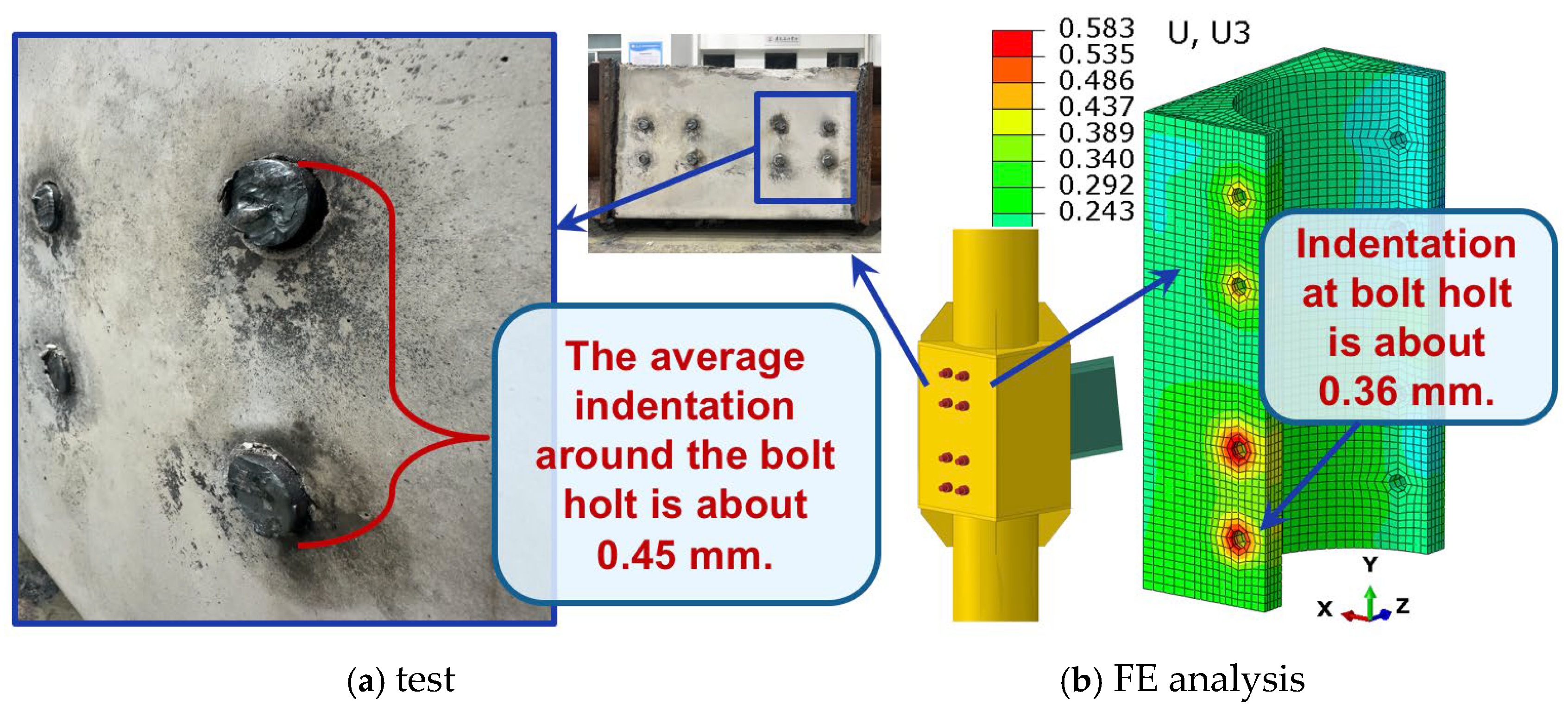
The localized compressive deformation of the high-strength grout is mainly concentrated at the locations where the bolt nuts directly bear against the square steel tube wall. After completion of the quasi-static test, a grout indentation of approximately 0.45 mm relative to the surrounding area was measured at the bolt holes on the side opposite the beam, whereas the corresponding value obtained from the finite element analysis was about 0.36 mm (see Figure 12). To adequately account for the creep effect of the grout in the test specimen, the prestress in the high-strength bolts was maintained for more than six months during the experimental program, whereas this effect was not considered in the finite element analysis. Despite this difference, the indentation values from both approaches are relatively small and show good agreement, thereby validating the reliability of the finite element model. For the benchmark joint, the corresponding joint rotations are approximately 0.1% and 0.08%, respectively, which are below the prescribed limit of 0.2% defined in Equation (4).
The experimental results indicate that the high-strength grout maintained good integrity in the regions surrounding the bolt holes where compressive stresses were concentrated, with only minor local spalling observed at the corners of a few bolt holes (as shown in Figure 13), with a spalling width of approximately 1 mm. The finite element analysis similarly shows that compressive damage in the grout is primarily concentrated at the corner regions around the bolt holes. Under the beam-end ultimate bending moment, the compressive damage index still remained below the crushing threshold of 0.99, indicating that no significant compressive crushing occurred in the grout.

5.3. FEA Results

5.3.1. Effects of Grout Strength

The comparison of the moment–rotation relationships between Group A models (CONN-A) and the benchmark model (CONN-BCH) is presented in Figure 14. The results indicate that when the grout strength grade is not lower than C20, the proposed joint provides sufficient strength to allow full yielding of the beam plastic hinge. Owing to the confinement effect of the steel tubes, both the strength and ductility of the high-strength grout are significantly enhanced. Even when C20-grade grout is adopted, its ultimate strength under a triaxial stress state is substantially higher than the required design strength, resulting in a limited influence of grout strength on the overall joint capacity. Given the direct contribution and critical influence of the square steel tube wall on the bearing capacity, although the elastic modulus of C20 grout is 19% lower than that of C35 grout, the maximum grout indentation increases by only 10% and remains smaller than the design limit of 0.91 mm defined by Equation (4), as shown in Figure 15.

5.3.2. Effects of Square Steel Tube (SST) Wall Thickness

The comparison of the moment–rotation relationships between Group B models (CONN-B) and the benchmark model (CONN-BCH) is illustrated in Figure 16. The results demonstrate that the wall thickness of the square steel tube has a pronounced influence on joint behavior. When the wall thickness is reduced from 10 mm in the benchmark model to 8 mm, the moment–rotation response remains essentially unchanged, while the maximum grout indentation increases by approximately 0.2 mm. When the wall thickness is further reduced to 6 mm, the moment–rotation curve exhibits noticeable irregularities at a joint rotation of about 1.5%, and the growth rate of the maximum grout indentation increases significantly. With a further reduction in wall thickness to 4 mm, the bearing capacity provided by the steel tube wall decreases substantially, leading to localized compressive damage of the grout under the concentrated pressure exerted by the bolt nuts. Consequently, more pronounced strength degradation appears in the moment–rotation response starting at a joint rotation of approximately 1.0%.
Although the confinement effect provided by the steel tube wall is correspondingly weakened, except for localized surface damage at the nut bearing zones, the maximum strength attained by the high-strength grout remains higher than the design strength, allowing the beam plastic hinge to still reach its yield capacity. However, due to the significant reduction in the wall thickness of the square steel tube, the local stiffness of the high-strength grout is markedly reduced, resulting in a substantial increase in the maximum grout indentation. As shown in Figure 17, when the square steel tube wall thickness is smaller than 8 mm, the maximum grout indentation no longer satisfies the design requirement specified in Equation (4).

5.3.3. Effects of SST Height

The comparison of the moment–rotation relationships between Group C models (CONN-C) and the benchmark model (CONN-BCH) is presented in Figure 18. The results indicate that the height of the square steel tube has a negligible effect on both the strength and stiffness of the joint. As shown in Figure 19, with increasing square steel tube height, the maximum indentation of the high-strength grout decreases slightly, with the magnitude of reduction being insignificant. The primary factor influencing the strength and stiffness of the proposed connection is the degree of confinement provided to the high-strength grout in the locally compressed region. Increasing the height of the square steel tube provides additional grout confinement along the column axis to the grout surrounding the bolt hole. Although the slightly enhanced confinement does not noticeably affect the already sufficient connection strength, it marginally reduces the extent of local grout indentation.

5.3.4. Effects of SST Width

The comparison of the moment–rotation relationships between Group D models (CONN-D) and the benchmark model (CONN-BCH) is shown in Figure 20. The results indicate that the width of the square steel tube has a negligible influence on the joint strength and stiffness. As illustrated in Figure 21, with increasing square steel tube width, the maximum indentation of the high-strength grout decreases slightly, and the magnitude of this reduction can likewise be considered insignificant. Increasing the width of the square steel tube increases the grout thickness in the compression zone of the proposed connection. The dispersion effect enlarges the effective bearing area of the grout, thereby reducing the compressive stress and slightly decreasing the extent of grout indentation. Since the change in grout confinement is limited, the connection strength is not significantly affected.

5.3.5. Effects of Column Axial Load

The comparison of the moment–rotation relationships between Group E models (CONN-E) and the benchmark model (CONN-BCH) is presented in Figure 22. The results indicate that the axial compressive load in the CCFT column has a negligible effect on the flexural strength and stiffness of the joint. Although the stress in the circular steel tube wall increases with increasing axial load, variations in column axial force have little influence on the confinement provided to the grout, provided that the strength requirements of the column are satisfied, the influence of column axial load on the flexural capacity of the proposed joint remains limited.
As shown in Figure 23, when the column axial load is relatively small, the grout indentation decreases slightly; however, with further increases in axial load, a tendency for increased indentation is observed. Overall, the effect of column axial load on the maximum indentation of the high-strength grout is also insignificant.

5.3.6. Failure Modes Discussion

Considering the potential influence of buckling behavior in steel structures, local and global buckling phenomena have been widely discussed in previous studies (e.g., [39]). In the proposed connection system, when the applied load approaches the ultimate capacity of the beam, local buckling may occur in the flange and web within the beam plastic hinge region. This response is commonly observed in robust moment-resisting connections and indicates that the beam has reached its ductile limit state.
However, both numerical results in this study and previous quasi-static test results show that neither local nor global buckling occurs in the connection region itself within the investigated parameter range. The connection components remain stable, and the structural response is primarily governed by the compressive behavior of the confined high-strength grout and the load transfer mechanism between the beam endplate and the CCFT column. Therefore, the occurrence of local buckling is limited to the beam plastic hinge region and does not compromise the integrity of the proposed connection.

6. Bolt Length Impact on Connection Stiffness

As discussed previously, although the proposed joint employs through-type long bolts, the bolt length does not affect the joint stiffness provided that an appropriate level of prestress is applied. Taking the benchmark joint as an example, the theoretical yield moment of the HN450 × 200 × 9 × 14 steel beam at the end plate is 469 kN·m, corresponding to a maximum tensile force of 265.8 kN in a single bolt, as calculated using Equation (3). According to GB50017 [35], a prestress of 355 kN can be applied to a 10.9S-grade M30 high-strength bolt. Under this prestress level, the bolt length has no influence on joint stiffness at the joint yield state.
The theoretical ultimate moment of the beam end plate is 683 kN·m, at which the maximum tensile force in a single bolt reaches 387 kN, exceeding the applied prestress by 32 kN. Under this condition, the bolt elongation is only 0.124 mm, resulting in an additional endplate rotation of approximately 0.03%, which can be considered negligible. Even with a 50% loss of prestress, only a 0.16% joint rotation is induced, resulting in a minimal impact on connection stiffness. These results demonstrate that the proposed joint is capable of satisfying the requirements of a fully rigid connection. Moreover, by adjusting the level of bolt prestress, a semi-rigid connection can also be achieved, thereby accommodating specific structural performance demands.

7. Conclusions

A rigid connection between CCFT columns and WF steel beams has been proposed to address the limitations of existing joint configurations, including complex construction and irrational force-transfer mechanisms. This study presents a complete design procedure for the proposed joint and investigates the key factors influencing its flexural performance through finite element analysis. The main conclusions are summarized as follows:
  • The proposed joint design procedure can produce a stable and reliable fully rigid connection. The results suggest that the proposed connection can be adopted in practical design where high flexural strength and stiffness are required.
  • The wall thickness of the square steel tube should be considered a key design parameter. A 60% reduction in tube wall thickness significantly reduces the bearing capacity of the high-strength grout and results in a 503% increase in local indentation under concentrated nut pressure.
  • The constraints on square tube dimensions and column axial load may be relaxed within the practical engineering range. A 30% increase in tube height and width results in only 6.8% and 8.8% changes in grout indentation, respectively. Therefore, adopting the minimum square tube size that satisfies construction requirements is recommended to reduce both cost and overall joint dimensions.
  • Due to the confinement provided by the square steel tube, a 40% reduction in grout strength has only a minor effect on connection flexural performance, resulting in just a 9.9% increase in grout indentation. The confinement also enhances grout compressive strength and ductility, thereby reducing the risk of brittle joint failure.
  • By adjusting the prestress in the through-type long bolts, either fully rigid or semi-rigid connections can be achieved, allowing the joint to meet different structural performance demands.

8. Future Work

The proposed connection transfers the beam-end moment to the concrete-filled circular steel tube column through the endplate and nut bearing pressure by optimizing the force transfer path. This design prevents radial tension in the steel tube, reduces separation between the tube wall and the core concrete, and minimizes potential cyclic opening–closing behavior under seismic loading. To reduce computational cost, contact interactions between components were simplified, and detailed nonlinear contact evolution was not explicitly modeled. Moreover, the optimized force transfer path eliminates key components subjected to repeated tension–compression reversals under seismic action, and all welding is completed in the factory, reducing the risk of cyclic degradation and pinching. Therefore, monotonic loading was adopted in the parametric analysis of this study.
In future research, the conclusions drawn in this study can be further validated through quasi-static experiments. Investigations involving components of varying sizes could be conducted to verify the general applicability of the proposed design methodology. Additionally, the potential effects of fabrication and installation tolerances, temperature variations, and long-term loading on joint performance could be explored.

Author Contributions

Conceptualization, Y.G.; methodology, Y.G. and D.Y.; software, Y.G.; validation, D.Y. and W.G.; formal analysis, Y.G.; data curation, Y.G.; writing—original draft preparation, Y.G.; writing—review and editing, D.Y. and W.G.; funding acquisition, Y.G. All authors have read and agreed to the published version of the manuscript.

Funding

This research received no external funding.

Institutional Review Board Statement

Not applicable.

Informed Consent Statement

Not applicable.

Data Availability Statement

The original contributions presented in this study are included in the article. Further inquiries can be directed to the corresponding author.

Conflicts of Interest

The authors declare no conflicts of interest.

Nomenclature

The following symbols are used in this manuscript:
A 1 Area of the applied load
A 2 Bearing surface area
A c = b p × h c
A n b Net area of each bolt
A n n Contact area between a single bolt nut and the square steel tube wall
B Width
E b Bolt elastic modulus
E g High-strength grout stiffness
F g , r e q Axial compressive strength of the high-strength grout
F y b Bolt yield strength
F v b Bolt shear strength
H Height
L Length
L b Original bolt length
L n Distance between both plastic hinges on beam ends
M h Beam-end plastic hinge moment
M f Maximum moment at the square steel tube wall
N b Bolt number
P f 1 Maximum   tensile   force   in   a   sin gle   bolt   under   the   beam - end   moment   M f
V h Beam   end   shear   force   under   beam - end   moment   M h
b p Endplate width
d Beam depth
f b Bolt tensile stress
f c Uniaxial compressive strength
f g , b Compressive stress imposed on the high-strength grout by the bolt nuts
f g , e p Compressive stress imposed on the high-strength grout
f u Tensile strength
f v Bolt shear stress
f y Yield strength
h c Distance from the centroid of the beam compression flange to the nearest edge of the endplate
h i i = 1 , 2 ; distances from the center of the tension bolts to the centroidal axis of the beam compression flange
n b Number of bolts per row
t Thickness
t b f Beam flange thickness
t g Average grout thickness at the bolt hole
Strength reduction factor; Diameter;
β Bolt tensile stress to yield strength ratio
ρ Bolt pretension ratio
γ Strength adjustment factor
θ g r t Joint rotation caused by bolt rigid-body displacement
ε y b Bolt yield strain

References

  1. Shams, M.; Saadeghvaziri, M.A. State of the art of concrete-filled steel tubular columns. Struct. J. 1997, 94, 558–571. [Google Scholar] [CrossRef]
  2. Chacón, R. Circular concrete-filled tubular columns: State of the art oriented to the vulnerability assessment. Open Civ. Eng. J. 2015, 9, 249–259. [Google Scholar] [CrossRef]
  3. Chacón, R.; Mirambell, E.; Real, E. Strength and ductility of concrete-filled tubular piers of integral bridges. Eng. Struct. 2013, 46, 234–246. [Google Scholar] [CrossRef]
  4. Varma, A.H.; Ricles, J.M.; Sause, R.; Lu, L.W. Seismic behavior and modeling of high-strength composite concrete-filled steel tube (CFT) beam–columns. J. Constr. Steel Res. 2002, 58, 725–758. [Google Scholar] [CrossRef]
  5. Zubydan, A.H.; ElSabbagh, A.I. Monotonic and cyclic behavior of concrete-filled steel-tube beam-columns considering local buckling effect. Thin-Walled Struct. 2011, 49, 465–481. [Google Scholar] [CrossRef]
  6. Elchalakani, M.; Zhao, X.-L.; Grzebieta, R.H. Concrete-filled circular steel tubes subjected to pure bending. J. Constr. Steel Res. 2001, 57, 1141–1168. [Google Scholar] [CrossRef]
  7. Dai, X.; Lam, D. Shape effect on the behaviour of axially loaded concrete filled steel tubular stub columns at elevated temperature. J. Constr. Steel Res. 2012, 73, 117–127. [Google Scholar] [CrossRef]
  8. Azizinamini, A.; Schneider, S.P. Moment connections to circular concrete-filled steel tube columns. J. Struct. Eng. 2004, 130, 213–222. [Google Scholar] [CrossRef]
  9. Yang, Y.; Liu, X.; Zhang, J.; Liu, J.; Cheng, W. Behavior of large-scale connections between circular concrete-filled steel tubular columns and H-section steel beams. Adv. Struct. Eng. 2020, 23, 307–319. [Google Scholar] [CrossRef]
  10. Sohaei, S.; TahamouliRoudsari, M.; Memarzadeh, P. Numerical Investigation of I-Shaped Beam to Concrete Filled Tube Column Connection Without Continuity Plate. Int. J. Steel Struct. 2021, 21, 2071–2087. [Google Scholar] [CrossRef]
  11. Schneider, S.P.; Alostaz, Y.M. Experimental behavior of connections to concrete-filled steel tubes. J. Constr. Steel Res. 1998, 45, 321–352. [Google Scholar] [CrossRef]
  12. Alostaz, Y.M.; Schneider, S.P. Analytical behavior of connections to concrete-filled steel tubes. J. Constr. Steel Res. 1996, 40, 95–127. [Google Scholar] [CrossRef]
  13. Wang, J.-F.; Han, L.-H.; Uy, B. Behaviour of flush end plate joints to concrete-filled steel tubular columns. J. Constr. Steel Res. 2009, 65, 925–939. [Google Scholar] [CrossRef] [PubMed]
  14. Wang, J.F.; Chen, L.P. Experimental investigation of extended end plate joints to concrete-filled steel tubular columns. J. Constr. Steel Res. 2012, 79, 56–70. [Google Scholar] [CrossRef]
  15. Li, Y.L.; Chan, T.M.; Zhao, X.L. Review on blind bolted connections to concrete-filled steel tubes. Thin-Walled Struct. 2023, 183, 110444. [Google Scholar] [CrossRef]
  16. Wang, Z.B.; Tao, Z.; Li, D.S.; Han, L.H. Cyclic behaviour of novel blind bolted joints with different stiffening elements. Thin-Walled Struct. 2016, 101, 157–168. [Google Scholar] [CrossRef]
  17. Cheng, C.T.; Chung, L.L. Seismic performance of steel beams to concrete-filled steel tubular column connections. J. Constr. Steel Res. 2003, 59, 405–426. [Google Scholar] [CrossRef]
  18. Ramirez Ortiz, C.; Areiza Palma, G.; Gutierrez Amador, A.D.; Ramirez Duque, J.L.; Cano Buitron, R.E.; Gonzales Escobar, L.F. Seismic behavior of a steel beam-to-concrete-filled steel tubular column connection using external diaphragms. Appl. Sci. 2022, 12, 3618. [Google Scholar] [CrossRef]
  19. Habibi, A.; Fanaie, N.; Shahbazpanahi, S. Experimental and numerical investigation of I-beam to concrete-filled tube (CFT) column moment connections with pipe-stiffened internal diaphragm. J. Constr. Steel Res. 2023, 200, 107648. [Google Scholar] [CrossRef]
  20. Nishiyama, I.; Fujimoto, T.; Fukumoto, T.; Yoshioka, K. Inelastic force-deformation response of joint shear panels in beam-column moment connections to concrete-filled tubes. J. Struct. Eng. 2004, 130, 244–252. [Google Scholar] [CrossRef]
  21. Morino, S.; Tsuda, K. Design and construction of concrete-filled steel tube column system in Japan. Earthq. Eng. Eng. Seismol. 2003, 4, 51–73. [Google Scholar]
  22. Koloo, F.A.; Badakhshan, A.; Fallahnejad, H.; Jamkhaneh, M.E.; Ahmadi, M. Investigation of proposed concrete filled steel tube connections under reversed cyclic loading. Int. J. Steel Struct. 2018, 18, 163–177. [Google Scholar] [CrossRef]
  23. Elremaily, A.; Azizinamini, A. Design provisions for connections between steel beams and concrete filled tube columns. J. Constr. Steel Res. 2001, 57, 971–995. [Google Scholar] [CrossRef]
  24. Khanouki, M.A.; Sulong, N.R.; Shariati, M.; Tahir, M.M. Investigation of through beam connection to concrete filled circular steel tube (CFCST) column. J. Constr. Steel Res. 2016, 121, 144–162. [Google Scholar] [CrossRef]
  25. Beutel, J.; Thambiratnam, D.; Perera, N. Cyclic behaviour of concrete filled steel tubular column to steel beam connections. Eng. Struct. 2002, 24, 29–38. [Google Scholar] [CrossRef]
  26. Sheet, I.S.; Gunasekaran, U.; MacRae, G.A. Experimental investigation of CFT column to steel beam connections under cyclic loading. J. Constr. Steel Res. 2013, 86, 167–182. [Google Scholar] [CrossRef]
  27. Li, X.; Xiao, Y.; Wu, Y.T. Seismic behavior of exterior connections with steel beams bolted to CFT columns. J. Constr. Steel Res. 2009, 65, 1438–1446. [Google Scholar] [CrossRef]
  28. Gao, Y.; Zhu, P.; Liu, J.; Lou, F. Seismic Behavior and Resilience of an Endplate Rigid Connection for Circular Concrete-Filled Steel Tube Columns. Buildings 2025, 15, 2035. [Google Scholar] [CrossRef]
  29. Miller, D.K. Lessons learned from the Northridge earthquake. Eng. Struct. 1998, 20, 249–260. [Google Scholar] [CrossRef]
  30. Bertero, V.V. Performance of Steel Building Structure During the Northridge Earthquake; Report EERC-94/09; University of California: Berkeley, CA, USA, 1994. [Google Scholar]
  31. Bertero, V.V. Seismological and Engineering Aspects of the January 17, 1995 Hyogoken-Nanbu (Kobe) Earthquake; Report EERC-95/10; University of California: Berkeley, CA, USA, 1995. [Google Scholar]
  32. ANSI/AISC 358; Prequalified Connections for Special and Intermediate Steel Moment Frames for Seismic Applications. American Institute of Steel Construction: Chicago, IL, USA, 2022.
  33. ANSI/AISC 341; Seismic Provisions for Structural Steel Buildings. American Institute of Steel Construction: Chicago, IL, USA, 2016.
  34. ACI 318; Building Code Requirements for Structural Concrete and Commentary. ACI Committee: Farmington Hills, MI, USA; American Concrete Institute: Farmington Hills, MI, USA, 2008.
  35. GB 50017; Code for Design of Steel Structures. China Standard Press: Beijing, China, 2017.
  36. GB/T 1596; Code for Fly Ash Used for Cement and Concrete. China Standard Press: Beijing, China, 2005.
  37. GB/T 21236; Code for Silica Fume from Electric-Furnace. China Standard Press: Beijing, China, 2007.
  38. GB 50010; Code for Design of Concrete Structures. China Standard Press: Beijing, China, 2015.
  39. Azizi, H.; Ahmadi, J.; Kazemi, F. Enhancing seismic resilience in steel frames with synchronized double-stage yield buckling-restrained braces. Soil Dyn. Earthq. Eng. 2025, 198, 109587. [Google Scholar] [CrossRef]
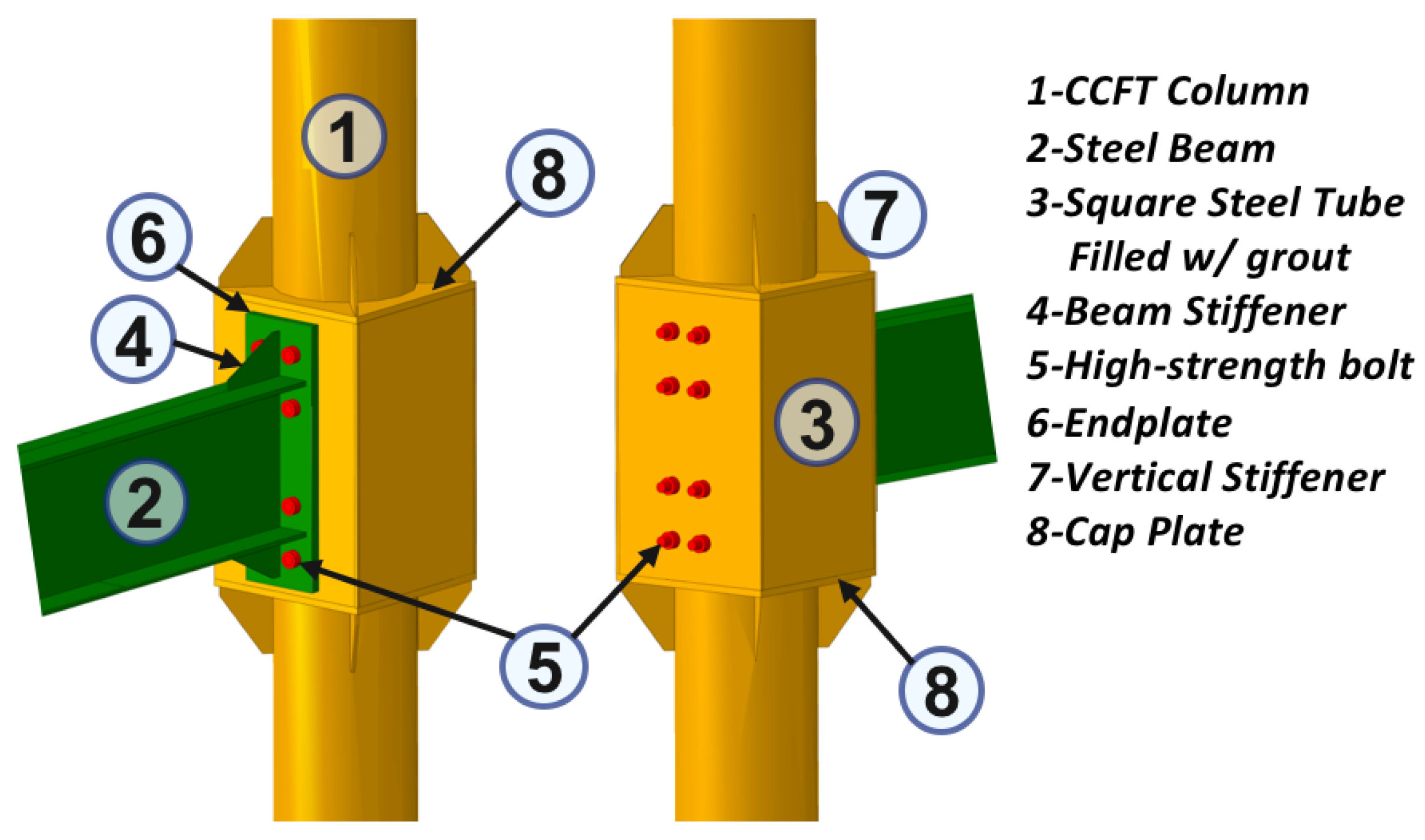
Figure 1. The Novel Connection Details.
Eng 07 00158 g001
Figure 2. Bolt Group Force Model.
Eng 07 00158 g002
Figure 3. Benchmark Connection Details (Length Unit: mm).
Eng 07 00158 g003
Figure 4. Benchmark Connection Model in ABAQUS.
Eng 07 00158 g004
Figure 5. FE Model Assembly and Meshing Condition.
Eng 07 00158 g005
Figure 6. Boundary & Load Condition.
Eng 07 00158 g006
Figure 7. Load Case.
Eng 07 00158 g007
Figure 8. Simplified Steel Stress–Strain Curve.
Eng 07 00158 g008
Figure 9. Unconfined Uniaxial Concrete & Grout Stress–Strain Curve.
Eng 07 00158 g009
Figure 10. The Damage Parameters for the CDP Model.
Eng 07 00158 g010
Figure 11. Comparison of Results between FE Analysis and the Experimental Test.
Eng 07 00158 g011
Figure 12. Grout Indentation around the Bolt Hole.
Eng 07 00158 g012
Figure 13. Grout Damage around the Bolt Hole.
Eng 07 00158 g013
Figure 14. Moment–Rotation Curves for Group A Models.
Eng 07 00158 g014
Figure 15. Grout Indentation for Group A Models.
Eng 07 00158 g015
Figure 16. Moment–Rotation Curves for Group B Models.
Eng 07 00158 g016
Figure 17. Grout Indentation for Group B Models.
Eng 07 00158 g017
Figure 18. Moment–Rotation Curves for Group C Models.
Eng 07 00158 g018
Figure 19. Grout Indentation for Group C Models.
Eng 07 00158 g019
Figure 20. Moment–Rotation Curves for Group D Models.
Eng 07 00158 g020
Figure 21. Grout Indentation for Group D Models.
Eng 07 00158 g021
Figure 22. Moment–Rotation Curves for Group E Models.
Eng 07 00158 g022
Figure 23. Grout Indentation for Group E Models.
Eng 07 00158 g023
Table 1. Benchmark Connection Dimensions and Actual Material Strengths.
ItemTag L B H t f y f u f c
( m m ) ( M P a )
Circular Tube 406 × 10 406---10273355-
Square Tube 520 × 520 × 10 -52052082010288378-
Beam Flange t f --200-14285374-
Beam Web t w ---4509293391-
Endplate t e p --24077030250362-
Bolt M 30 × 600 30600---9401040-
Beam Stiffener t s b -225-13010288378-
Cap Plate t c -520520-20265367-
Tube Stiffener t s t --15026010288378-
Core ConcreteC40386------28.2
Infilled GroutC35-500500820---22.5
Beam-Endplate WeldFull Penetration------430-
Other WeldsFillet----8-430-
Note: Dimensions are given in millimeters (mm), including diameter (∅), length (L), width (B), height (H), and thickness (t). Material strengths are expressed in megapascals (MPa), where f y , f u , and f c denote yield strength, tensile strength, and uniaxial compressive strength, respectively. The material properties were consistent with those adopted in previous tests [28].
Table 2. Mixture compositions of the concrete and high-strength grout used in this study.
ConstituentConcrete
(kg·m−3)
High-Strength Grout (kg·m−3)
Cement445400
Fly Ash5565
Silica Fume-85
Water175120
Superplasticizer (L·m−3)1.42.0
Fine Aggregate690800
Coarse Aggregate1035-
Note: The material properties were consistent with those adopted in previous tests [28].
Table 3. The Plasticity Parameters for the CDP Model.
Dilation AngleEccentricityfb0/fc0KViscosity Parameter
360.11.160.6670
Table 4. Parameters for FEA Models.
NameHigh-Strength GroutSquare Steel TubeAxial Load
Grade f c ( MPa ) E g ( MPa ) t (mm) H (mm) B (mm) P u / P c
CONN-BCHC3522.531,500108205200.0
CONN-A1C3020.130,000 * * * *
CONN-A2C2516.728,000 * * * *
CONN-A3C2013.425,500 * * * *
CONN-B1 * * * 8 * * *
CONN-B2 * * * 6 * * *
CONN-B3 * * * 4 * * *
CONN-C1 * * * * 902 * *
CONN-C2 * * * * 984 * *
CONN-C3 * * * * 1066 * *
CONN-D1 * * * * * 572 *
CONN-D2 * * * * * 624 *
CONN-D3 * * * * * 676 *
CONN-E1 * * * * * * 0.2
CONN-E2 * * * * * * 0.4
CONN-E3 * * * * * * 0.6
Note: Parameters identical to those of the benchmark connection CONN-BCH are marked with an asterisk (*). P u and P c are axial load and axial capacity of the CCFT column. Height and width set to 1.1, 1.2, and 1.3 times those of the benchmark connection.
Disclaimer/Publisher’s Note: The statements, opinions and data contained in all publications are solely those of the individual author(s) and contributor(s) and not of MDPI and/or the editor(s). MDPI and/or the editor(s) disclaim responsibility for any injury to people or property resulting from any ideas, methods, instructions or products referred to in the content.