Abstract
In order to meet the needs of grid integration of various renewable energy sources and promote long-distance power transmission, a hybrid multi-infeed DC system architecture consisting of a line-commutated converter (LCC) and a modular multilevel converter (MMC) is constructed. Focusing on the issue of traditional differential protection refusing to operate under high-resistance grounding faults and failing under symmetrical faults, a dual-criteria protection mechanism is proposed in this paper. By integrating current differential and voltage criterion, the accurate identification of various types of AC line faults can be realized. A hybrid DC system simulation model was built on MATLAB, the sampled data was decoupled, and the differential quantity was calculated to test the dual-criteria protection mechanism. The simulation results show that the proposed protection mechanism can effectively identify various faults within the hybrid DC multi-feed system area and faults outside the area and has robustness to complex working conditions such as high-resistance grounding and three-phase short circuits, which improves the sensitivity, selectivity, and adaptability of the protection. This method is designed for AC line protection under the disturbance of multi-infeed DC systems. It is not directly applicable to pure DC microgrids. The concept can be extended to AC/DC hybrid microgrids by adding DC-side protection criteria and re-calibrating thresholds.
1. Introduction
In recent years, with the large-scale access of renewable energy and the advancement of the cross-regional optimization of power resources, high-voltage direct current (HVDC) technology has developed rapidly [1]. Notably, hybrid transmission topology that combines traditional LCC with flexible MMC has been applied in many engineering projects due to its comprehensive advantages in loss control, voltage support, and power regulation [2,3]. However, while the hybrid LCC-MMC topology improves transmission capacity and operational flexibility, it also introduces new protection challenges. Especially under fault conditions, the differences in converter structure and control strategy cause the system to exhibit characteristics such as multi-source dynamic injection, strong electrical quantity coupling, and complex transient processes, causing unprecedented challenges in line protection [4]. Among these challenges, the protection of DC overhead lines is directly related to the safety and stability of system operation.
In current engineering practice, the protection of hybrid topology systems is still based on traditional strategies, but it has faced adaptability challenges in the new environment [5]. The line protection of the hybrid LCC-MMC HVDC transmission system still uses the basic framework of the traditional LCC-HVDC system in terms of structure, and most of the main protection adopts non-unit protection strategies, such as protection methods based on the traveling wave principle. This type of method relies on the high-frequency fluctuation characteristics of the initial fault, and can complete fault location and removal within a few milliseconds, with an extremely high operating speed [6]. However, the sensitivity of traveling wave protection to high fault resistance or multi-terminal injection scenarios is significantly reduced. Once the traveling wave signal is attenuated or distorted, protection failure or misclassification problems are likely to occur [7]. Therefore, in actual projects, current differential protection is often configured as a backup measure to improve the coverage of high-impedance faults and complex topology scenarios.
However, in hybrid LCC-MMC DC systems, the traditional differential current protection criteria are not fully applicable. Studies have shown that there are significant differences in the current response mechanisms of LCC and MMC at the initial stage of a fault: when a fault occurs in an MMC, its submodule capacitors quickly release stored energy, accompanied by the switching of the PWM control logic, which often leads to high-frequency pulses and instantaneous dynamic current components being injected into the line [8], while the LCC mainly presents a slow rise in short-circuit current and lacks high-frequency disturbance characteristics [9]. In the multi-terminal system, when two converters are connected to the same protection area at the same time, the heterogeneous injection characteristics will cause short-term asymmetric fluctuations in the differential current, which can easily lead to misjudgment or protection failure [10]. Therefore, in the LCC-MMC multi-terminal system, the differential protection scheme based only on the traditional current difference can no longer meet the accuracy and reliability requirements under multi-source dynamic disturbances, and the introduction of new criteria to enhance robustness and reliability is urgently needed.
In order to improve the adaptability of differential protection in LCC-MMC multi-terminal systems, the differential protection method based on the improved differential criterion has been widely studied in recent years. It can be divided into the following two main categories: one is the improved current criterion, and the other is the non-current auxiliary quantity criterion.
In terms of the improved current criterion, reference [11] constructs a differential current based on a frequency-dependent distributed parameter model and introduces a fast convolution algorithm, which significantly improves the sensitivity and modeling accuracy of long-distance line faults. However, it has high requirements regarding the line parameters and synchronous sampling accuracy, and the actual deployment is complicated. Reference [12] introduces amplitude and phase angle correction factors to dynamically compensate for the heterogeneous injection behavior of MMCs at the early stage of a fault, which improves the adaptability and robustness of the criterion. However, it relies on typical operation models and lacks generalization ability. Reference [13] proposed a delay-compensated differential current construction method to solve the delay problem of sequence component extraction caused by the access of distributed power sources and introduced the frequency characteristic ratio (FCR) to enhance the disturbance recognition capability. This method is suitable for scenarios with inverter sources, but its robustness to frequency drift and load disturbances is still limited. Reference [14] used the Sigmoid function to reconstruct the braking characteristics, which enhanced the recognition capability when the phase angle was close to 90°. However, the parameter setting was complex, and it was easy to cause a saturation response under short-circuit shock. Reference [15] introduced the MMC negative sequence current difference as an auxiliary criterion to improve the sensitivity of asymmetric fault recognition. However, when there are multiple feeds or the system fluctuates violently, the negative sequence component is easily disturbed, and there is a risk of misjudgment. Reference [16] proposed a differential current and fault pole identification method based on modulus value, which effectively improved the selectivity, speed, and sensitivity of protection but required higher calculation accuracy in complex frequency change environments. Reference [17] proposed a longitudinal protection method based on the fault current difference for flexible DC distribution networks, which has absolute selectivity and strong resistance to transition resistance but low requirements for communication synchronization and is suitable for distributed scenarios.
In terms of non-current auxiliary quantity judgment, reference [18] proposed a polarity identification method based on the directionality of bus voltage mutation, which effectively improved the ability to distinguish high-impedance faults but was sensitive to voltage measurement noise. Reference [19] constructed a U-Q characteristic curve to reflect the difference in the converter’s response to voltage and reactive power and realized fault section division, which is suitable for LCC-MMC hybrid systems but relies on high-precision reactive power extraction. Reference [20] uses the voltage mutation amplitude and change rate to construct the direction criterion, which reduces the dependence on current synchronization but is more sensitive to high-frequency disturbances. Reference [21] uses Tellegen theorem to construct the energy conservation criterion, which is suitable for fast fault identification in the receiving-end AC system but has high requirements for measurement point synchronization and measurement accuracy. Reference [22] calculates the energy mutation difference at both ends of the converter station for section judgment. It has a simple structure and does not require communication. It is suitable for boundary judgment, but it is more dependent on the station-side reactance configuration. Reference [23] proposed a polarity criterion based on the arrival time difference between zero-mode and line-mode traveling waves, which has high speed but is sensitive to reflection and sampling bandwidth. Reference [24] combined voltage fluctuation trend and direction information to construct a composite criterion, which enhances the ability to identify inter-pole faults, but the algorithm is complex and requires a high level of real-time computing performance.
Additionally, protection in MTDC systems interfacing with AC grids is not limited to fault-current-based approaches; frequency and voltage stability issues are also critical. Reference [25] proposed a methodology for tuning supervisory and frequency–response control systems in MTDC grids to support AC grids during over-frequency events. Reference [26] developed a droop-based coordinated voltage regulation and power-sharing strategy in hybrid AC–MTDC systems by embedding frequency control loops into MMCs. On the DC protection side, Reference [27] presented a hybrid fault-detection algorithm for MTDC systems that is capable of detecting multiple fault types using local measurements and a learning-based detection pool. Reference [28] proposed a high-speed single-ended protection method for MMC–MTDC grids using discrete wavelet analysis and a decision tree, achieving detection within 0.2 ms. Reference [29] provided a comprehensive review of DC fault protection methods in VSC-based HVDC and MTDC networks.
In summary, although existing studies have achieved certain results in the construction of differential protection criteria and the extraction of auxiliary quantities, they still face three challenges in the complex LCC-MMC multi-infeed topology. (1) The heterogeneous dynamic responses of multiple types of converters lead to a significant increase in the short-term asymmetric fluctuations of the differential current, and the existing current criteria are prone to false operation or refusal to operate. (2) Some non-current auxiliary criteria are highly dependent on synchronous sampling, voltage measurement, or system models, and the actual engineering deployment is complex. (3) Most current methods still focus on the construction of single-information-channel criteria and lack a comprehensive identification ability under the coupling of multiple disturbances and multi-modal characteristics.
Therefore, a dual-threshold differential protection method that integrates a voltage-change rate auxiliary channel is proposed in this paper. Based on the reconstruction of the disturbance rejection differential current, this method introduces the short-term change rate of the DC bus voltage as an auxiliary action condition and constructs a dual-threshold criterion logic, thereby enhancing the robustness and selectivity of the protection under the background of dynamic disturbances and effectively coping with key challenges such as multi-source heterogeneous injection, decreased sensitivity of current criterion, and single-channel information dependence.
The main work of this paper is as follows:
- (1)
- A multi-infeed DC system model considering the heterogeneous injection characteristics of LCC and MMC is constructed, and typical internal fault and disturbance conditions are simulated to reveal the coupling interference path of multi-source injection on the differential current.
- (2)
- A differential quantity reconstruction method based on disturbance stripping is proposed to effectively filter out the transient components caused by the dynamic control of the converter and improve the purity of the differential criterion.
- (3)
- The short-term change rate of the bus voltage is introduced as an auxiliary criterion channel to construct a dual-threshold protection criterion. On the basis of ensuring sensitivity, the ability to suppress non-fault disturbances is enhanced.
- (4)
- The method proposed in this paper is verified through the simulation of various working conditions in terms of action accuracy, stability, and misjudgment suppression ability in complex scenarios such as high-resistance grounding, weak synchronous disturbance, and multi-infeed dynamic injection.
2. Line Model and Parameter Decoupling of Multi-Infeed System
In order to realize the construction and verification of the above differential criterion, it is necessary to construct a multi-infeed system line model with transient resolution capability based on the converter characteristics and electrical disturbance laws as the basis for protection analysis and criterion design.
2.1. Line Model Selection
In the hybrid multi-feed system for renewable energy transmission, the receiving AC line is often in a complex environment of multi-source coupling, long-distance transmission, and multi-converter injection disturbance. The transient behavior of the line at the initial stage of the fault is significantly affected by the characteristics of the distributed parameters. If only the traditional concentrated parameter model (such as the π-type model) is used, it is difficult to accurately describe the transient wave propagation and phase difference evolution characteristics, which in turn affects the accuracy and sensitivity evaluation of the differential protection.
In order to more realistically reflect the propagation mechanism of voltage and current in the transmission line, the Bergeron model to model the AC line is adopted in this paper [30,31,32]. This method is a typical distributed parameter model engineering implementation form, which can fully characterize the key electrical behaviors such as wave impedance characteristics, propagation delay, and distributed resistance loss in the line, and is suitable for transient process modeling and relay protection research.
In engineering calculations, the line is often divided into two sections, as shown in Figure 1. Assuming that the line segment is a lossless line, concentrated resistors are connected in series at both ends and in the middle of the line, with a middle resistance value of R/2, and concentrated resistors R/4 are connected in series at both ends, where the resistance value of the entire line is R. The equivalent circuit of Figure 1 is shown in Figure 2, which shows the equivalent circuit structure after the concentrated resistor is introduced, which can more accurately reflect the line distribution loss. After simplified derivation, Figure 2 eliminates m′, m″, n′ and n″, and obtains the equivalent circuit shown in Figure 3, which is the Bergeron model of the transmission line.
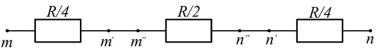
Figure 1.
Transmission lines considering resistance losses.
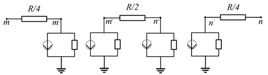
Figure 2.
Bergeron model of transmission line considering resistance loss.
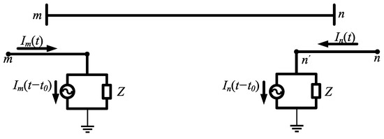
Figure 3.
Simplified Bergeron model of transmission line considering resistance loss.
In Equations (1) and (2), im(t), in(t) are the instantaneous currents at both ends of m and n. um(t), un(t) are the instantaneous voltages at both ends of m and n, Z is the converted line wave impedance, and t0 is the one-way propagation delay time of the electromagnetic wave in the line.
where im(t) and in(t) are the instantaneous currents at the endpoints, um(t) and un(t) are the voltages at the endpoints, Im(t − t0) and In(t − t0) are the delayed traveling wave current components, Z is the line characteristic impedance, and t0 is the signal delay time.
Equations (1) and (2) reveal the physical mechanism by which the terminal current is formed through the superposition of the incident wave excited by the local voltage and the reflected wave returned by the opposite end. The model fully considers the wave propagation delay, distributed loss, and reflection mechanism, and provides a solid modeling foundation for the subsequent construction of differential protection judgment criteria and action characteristic simulation. The above Bergeron model and related equations are based on the distributed parameter equivalent theory of transmission lines, referring to the water hammer theory proposed by Bergeron and its extension in power systems [30], and adopting the engineering implementation form proposed by Dommel in EMTP theory [31]. For some frequency-dependent characteristics, see Noda et al.’s extension method of the Bergeron unit [32].
2.2. System Structure and Parameter Decoupling Calculation
As shown in Figure 4, the hybrid multi-feed system studied in this paper consists of two different ±500 kV DC transmission lines, each of which adopts a bipolar and biterminal LCC-MMC hybrid structure. The two converter systems on the sending end are denoted as S1 and S2, and the corresponding equivalent impedances are ZS1 and ZS2. EM and EN represent the equivalent sources of the power grid at both ends. LCC-MMC1 and LCC-MMC2 inject AC power into the M-end bus in parallel with independent topologies, forming a complex multi-source feed-in structure.
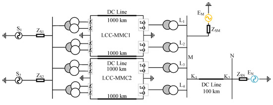
Figure 4.
Hybrid DC multi-infeed system topology.
The receiving end shares a section of the AC transmission line that is connected to the busbar. When the two DC systems are operating simultaneously, or in the event of a fault disturbance, the currents injected by S1 and S2 are coupled in space and time, resulting in spectral aliasing, transient asymmetry, and amplitude jumps in the line current. Especially in the early stages of a fault, the LCC exhibits a “fixed power” characteristic, and its injected disturbance frequency is low. The MMC has flexible current closed-loop control, a high disturbance frequency, and a fast rise time. The difference in their characteristics further amplifies the non-power frequency component of the differential quantity, seriously interfering with the protection criteria based on the centralized parameter model.
In the LCC-MMC system, the rectifier side is two groups of twelve-pulse thyristor converters connected in series, the inverter side is a three-phase modular multilevel converter, and the upper and lower bridge arms of the three-phase ABC are each composed of sub-modules (SMs) connected in series. The inverter-side power, current, etc., are input into the inner- and outer-loop control circuits, and the signal is output to the bridge arm to control the inverter-side converter.
The receiving end AC part is a 230 kV EM and EN dual-power supply system, whose equivalent impedance is represented by ZSM and ZSN, respectively. M and N are the installation positions of the protection units on both sides of the line. The main model parameters are shown in Table 1.

Table 1.
Model parameters.
Under multi-input conditions, especially when an asymmetric fault occurs in the line (such as single-phase grounding or a two-phase short circuit), the three-phase electrical quantities will show unbalanced characteristics, such as inconsistent amplitudes and obvious phase differences. At this time, in order to accurately extract the differential quantity and isolate the fault component, it is necessary to perform phase-decoupling processing on the line-end voltage and current signals. This paper adopts the Wedpohl phase mode transformation method to perform modal-decoupling on the measured electrical quantities, and the transformation matrix is shown as follows:
After transforming the three-phase voltage (or current) signals [SA, SB, SC]T at points M and N of the line, the corresponding zero-sequence, positive-sequence, and negative-sequence components [S(0), S(1), S(2)] can be obtained. The expressions are as follows:
where Sm(0), Sm(1), and Sm(2) are zero sequence, positive sequence, and negative sequence voltage (kV) or current (kA), respectively. SA, SB, and SC are voltage (kV) or current (kA) on both sides.
The mode current is synthesized into line current through inverse transformation. The inverse transformation process is
where S’A, S’B, S’C are the three-phase AC currents after decoupling.
This method can effectively decouple three-phase electrical quantities into independent modal channels and is particularly suitable for the current extraction and criterion reconstruction of differential protection under asymmetric working conditions. Figure 5 shows the waveforms of the phase A current and the positive-sequence current after phase A decoupling under a high-resistance grounding fault. By comparing the original waveform and the positive-sequence current waveform, it can be clearly seen that the positive-sequence current (red dotted line) after current decoupling is more stable and shows obvious periodicity. This shows that the current waveform, after decoupling, can effectively remove stray components and extract fault characteristics. In the high-resistance grounding fault scenario, the original current waveform (blue) has large noise and fluctuations, while the positive-sequence component can more clearly reflect the current changes caused by the fault, which is convenient for fault detection and analysis. This result shows that the decoupling process can significantly improve the detection sensitivity of high-resistance grounding faults, especially when the current changes are small.
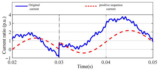
Figure 5.
Comparison of A-phase current and positive-sequence current waveforms under A-phase high-resistance grounding fault.
In summary, this section constructs a multi-input system line model that can reflect the disturbance characteristics of heterogeneous converters and realizes the pre-processing of differential quantity extraction through modal decoupling, providing a solid foundation for the subsequent construction and simulation verification of differential criteria.
3. Analysis of Differential Protection Performance in Multi-Infeed LCC-MMC System
Current differential protection generally adopts the ratio restraint action criterion [10], comparing the differential current with the restraint current to determine the appropriate protection action. As shown in Equations (7) and (8), IM and IN are the currents on both sides of line MN, Id and Ir are the differential current and restraint current, Id/Ir is the full current protection criterion, and K1 is the full current protection restraint coefficient.
3.1. Adaptability Analysis of Traditional AC Differential Protection in Multi-Infeed Systems
The adaptability of AC differential protection in multi-feedback systems is studied. In the model, the number of DC lines put into operation can be controlled to compare the DC feeds of different strengths.
As shown in Figure 4, the constructed system topology uses line MN as the differential protection area to simulate the complex working conditions of multiple groups of DC feed-in paths injected in parallel. The AC voltage at both ends of the system is 230 kV, and the total length of line MN is 50 km. By controlling the input of lines L1 to L4, it has the ability to configure a multi-feedback structure and can simulate typical multi-source injection disturbance conditions to study the impact of multi-source disturbances on protection criteria.
The four DC feed-in lines L1–L4 all adopt the LCC-MMC series commutation structure: the upstream is the LCC, which is transmitted 1000 km through the ±800 kV DC line and then connected to the downstream MMC, and finally injected into the AC bus M point from the MMC end. This typical structure reflects the power transmission mode that combines long-distance DC transmission with flexible terminal control and has good dynamic adjustment capabilities.
Putting L1 into the main circuit represents a single-channel LCC-MMC feeding structure, putting L1 and L2 into the main circuit represents a dual-channel parallel hybrid feeding, and putting L3 and L4 into the main circuit constitutes a hybrid multi-feed system with four groups of LCC-MMC branches transmitting power in parallel. Each commutation branch has differences in control response speed, disturbance mode, injection symmetry, etc., which constitute an important source of differential protection error.
In order to comprehensively evaluate the adaptability of traditional AC differential protection in multi-feed DC systems, this paper sets up multiple groups of representative typical fault conditions based on the aforementioned LCC-MMC hybrid DC sending end model and analyzes them from the perspectives of internal fault identification capability, external fault false operation risk, and high-resistance grounding fault refusal risk. The fault types cover three-phase short circuit, single-phase grounding, high-impedance grounding, and other fault scenarios to verify the robustness of the differential criterion in multi-feed systems.
3.1.1. Only-AC System
In this section, this paper analyzes the traditional differential protection action in an only-AC system. Through the simulation results, especially the protection action conditions listed in Table 2, this paper provides a detailed evaluation of the protection characteristics under different fault types and, combined with the simulation results shown in Figure 6, Figure 7, Figure 8 and Figure 9, verifies the adaptability of traditional current differential protection in the only-AC system.
Table 2.
Protection action of only-AC system.
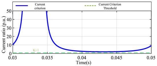
Figure 6.
Traditional A-phase current criterion for A-phase metal grounding fault.
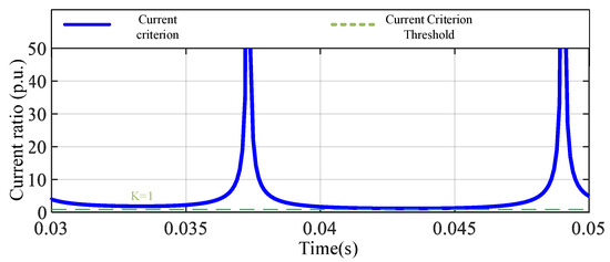
Figure 7.
Traditional A-phase current judgment for A-phase high-resistance grounding fault.
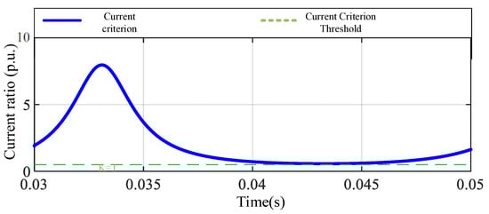
Figure 8.
Traditional A-phase current criterion for phase-to-phase fault.
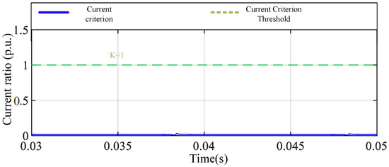
Figure 9.
Traditional A-phase current criterion for out-of-zone fault.
In the case of a metallic grounding fault, the protection criterion Id/Ir is greater than the set value K, so the protection system can operate successfully. The simulation result in Figure 6 shows that the metal grounding fault of phase A triggers the correct protection action. In the case of high-resistance grounding, although criterion Id/Ir is still greater than K, the sensitivity of the protection action decreases due to the increase in transition resistance. Simulation Figure 7 shows the current criterion response in this case, indicating that the high-resistance grounding fault can be detected, but may refuse to operate under certain extreme conditions. In the case of a phase-to-phase short-circuit fault, the protection criterion Id/Ir is always greater than K and can trigger the protection action. Figure 8 shows the simulation results of a phase-to-phase short-circuit fault, indicating that the protection system can respond stably. In the out-of-zone fault scenario, the protection criterion Id/Ir is less than K, ensuring that the protection system will not malfunction. The simulation results in Figure 9 confirm the correct response of the protection mechanism in out-of-zone faults.
The simulation analysis of the only-AC system shows that traditional differential protection can effectively cope with different types of faults. Notably, the protection system can work stably under metallic single-phase grounding and phase-to-phase short circuit faults. Although the sensitivity decreases in the case of high-resistance grounding faults, the protection system can still respond reliably in most cases. For out-of-zone faults, the system can avoid false operations and ensure the selectivity of the system.
3.1.2. LCC-MMC Multi-Feed System
In this section, the operation of traditional differential protection in an LCC-MMC multi-infeed system is analyzed. Through the simulation results, the protection characteristics under different fault types are evaluated, and the adaptability of traditional current differential protection in the LCC-MMC multi-infeed system is verified. Table 3 summarizes the protection actions of the LCC-MMC multi-infeed system under different faults.
Table 3.
LCC-MMC multi-infeed system protection action.
In the simulation diagram of the metal grounding fault of phase A in Figure 10, it can be observed that the current criterion Id/Ir fluctuates significantly at the beginning of the fault, and gradually decreases and approaches the K line after 0.035 s. Although the criterion briefly exceeds the threshold in the initial stage, it does not remain above K for a long time. This behavior indicates that the system may not be able to continuously meet the starting conditions under this type of fault, and there is a risk of protection refusal. From the perspective of the protection principle, this reflects the system’s insufficient ability to identify metallic single-phase grounding faults, indicating that the sensitivity of traditional differential protection decreases under the background of multiple feeds. In the case of a high-resistance grounding fault at phase A, the current criterion in Figure 11 fluctuates significantly, and the overall level is lower than or only briefly close to K, which cannot constitute an effective starting condition. The presence of transition resistance further weakens the measurable signal strength of the fault current, making it difficult for the protection system to perceive the occurrence of the fault. The simulation results show that the protection system fails to act under this type of fault, which manifests as refusal to act, exposing the serious sensitivity shortcomings of traditional differential protection when dealing with high-resistance grounding. For phase-to-phase short-circuit faults, the current criterion in Figure 12 fluctuates after the fault occurs. Although it is not always higher than K in some time periods, the overall trend is still significantly higher than the threshold level. The protection system can identify this type of internal fault and act in time. Simulation verification shows that despite certain instabilities, traditional differential protection still has a good performance under such fault conditions. In the out-of-zone fault scenario, the current criterion in Figure 13 shows a trend of alternating between high and low with fluctuating amplitudes. It is higher than K in some time periods and lower than K in some time periods, making it difficult to form a stable judgment. This volatility shows that under external disturbance conditions, there is a certain risk of misoperation in differential protection. The system may misjudge it as an internal fault due to current distortion or transient effects, thereby triggering unnecessary protection actions, reflecting the problem that differential protection is not selective and has an insufficient anti-interference ability in multi-feedback systems.
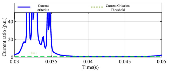
Figure 10.
Traditional A-phase current criterion for A-phase metal grounding fault.
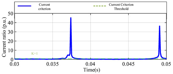
Figure 11.
Traditional A-phase current judgment for A-phase high-resistance grounding fault.
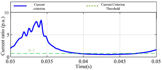
Figure 12.
Traditional A-phase current criterion for phase-to-phase fault.
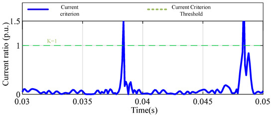
Figure 13.
Traditional A-phase current criterion for out-of-zone fault.
In summary, the adaptability of traditional current differential protection in LCC-MMC multi-feedback systems is obviously insufficient. Although protection can still be effectively triggered in typical internal fault conditions such as phase-to-phase short circuits, in the case of single-phase grounding, especially high-resistance grounding, the current criterion fails to remain above the action threshold, resulting in the protection’s refusal to operate. In addition, the criterion fluctuates greatly in out-of-zone faults, and the system is at risk of false operation, exposing the poor selectivity and anti-interference ability of traditional differential protection for fault identification in complex multi-feedback environments. Therefore, in the face of the operating characteristics of the hybrid access structure of LCC and MMC, the existing differential protection strategy can no longer meet the requirements of accurate, fast, and selective protection, and a more targeted improvement plan is urgently needed.
3.1.3. DC Feed Component Extraction
In the new hybrid multi-feed DC transmission system, due to the heterogeneity of the control strategies and response dynamics of each converter, inconsistent DC feed-in behaviors from multiple sources often occur at the beginning of the fault. These disturbances are superimposed on the differential current in a non-stationary form, which can easily lead to protection misjudgments or decreased action sensitivity. The traditional steady-state modeling method assumes that the system is in a linear periodic condition, which makes it difficult to characterize the above-mentioned non-power frequency dynamic characteristics. In order to achieve accurate equivalence and quantification of the feed-in components, this paper introduces the dynamic phasor method to model and extract them.
The dynamic phasor method projects the time-domain signal into the complex exponential basis space to obtain its frequency-domain “slow-varying component”—that is, the average frequency response characteristics within a short time window. This method is particularly suitable for system modeling problems containing high-order control, non-periodic disturbances, and frequency offset components. It can be expressed as
In Equation (9), ω0 is the fundamental angular frequency (line-frequency), p is the extracted harmonic order, and T is the observation window width.
The converter control trigger action in the hybrid system can be represented by the switching function Sip(t), and the inverter side feed current is represented by Idc. After the two are processed as dynamic phasors, the equivalent expression of the DC feed component can be obtained according to Equation (9):
where is the DC feed-in equivalent component at the pth frequency, is the (p − q)th order dynamic phasor of the inverter current signal, and is the qth order dynamic phasor of the switching function. Equation (10) reflects a convolution structure; that is, the feed-in current is composed of the spectrum reconstruction of the inverter injection current multiplied by its switching behavior.
When the analysis target is concentrated on the line-frequency component (i.e., p = q = 1), Equation (10) can be simplified to Equation (11):
where ˂Idc˃(0) is the DC (0th order) component of the DC current. ˂Sip˃(1) is the modulation coefficient of the switching behavior to the power frequency, defined as Equations (12) and (13):
In Equations (12) and (13): Ts is the switching period (s); ω is the angular frequency (rad/s); at this time, the phase of the DC feed component is determined by Siφ, and the amplitude is determined by Siφ and Idc.
Equation (13) essentially converts the nonlinear switching action into a modulation function, which is then multiplied by the DC current base value to form an equivalent AC injection model of the feed channel.
3.2. Analysis of the Reasons for the Decline in Adaptability
When a high-resistance grounding fault occurs in the area, the full-current differential protection is affected by the hybrid DC feed-in, and its sensitivity is reduced. This is similar to the refusal to operate when a high-resistance grounding fault occurs in a pure AC system. The fault-wiring diagram of the pure AC system is shown in Figure 14. In Figure 14, EM and EN are equivalent power sources on both sides of the AC system, Rg is the system transition resistance, Z1 and Z2 are equivalent system impedances on both sides of the AC line, and ZM and ZN are line impedances on both sides of the fault point. Let be the load current transmitted from the M terminal to the N terminal under normal operating conditions, is the changing current on the M side, is the changing current on the N side, and the capacitive current is ignored. The currents at both ends of M and N can be set as
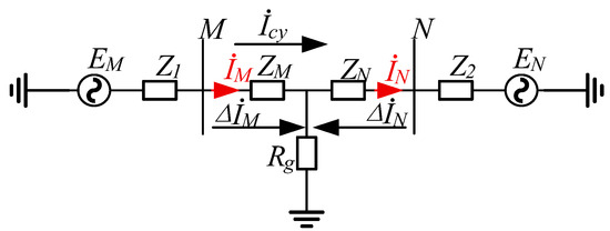
Figure 14.
Fault system wiring diagram of the only-AC system.
Since << and << , the action amount Id1 and the braking amount Ir1 of the traditional full current differential protection after taking into account the load current Icy can be expressed as
From Equations (15) and (16), it can be obtained that in the full-current criterion, the action amount Id1 is not affected by the load current, while the braking amount Ir1 increases with the increase in load current, and the protection sensitivity decreases accordingly. When the hybrid multi-DC is fed in, the AC system fault wiring is shown in Figure 15.
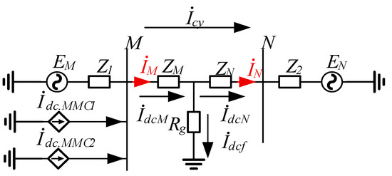
Figure 15.
Multi-infeed system fault system wiring.
Figure 15 shows the high-resistance ground fault wiring model in the hybrid LCC-MMC multi-feed scenario. and are the equivalent injection currents of the two sets of hybrid converters, is the total DC feed-in at the M end, and the current is divided into and at the fault point, which reflects the current coupling mechanism of multi-source disturbances in the protection area.
In Equations (17) and (18), and are DC input components (bias, low frequency).
Equations (15) and (16), when combined with Equations (17) and (18), can obtain the action amount Id2 and the braking amount Ir2 after multiple feeds as Equations (19) and (20), respectively.
From Equation (20), it can be obtained that, in full-current protection, as the transition resistance increases, the influence of the system load current is greater than the DC feed component, and under normal operation, the load current will increase with the DC feed, so that in the high-transition-resistance state, the load current is still the main influencing factor causing the increase in braking amount and the decrease in protection sensitivity.
4. Coordinated Differential Protection Method Based on Improved Current Criterion and Auxiliary Criterion
In order to alleviate the problem of decreased sensitivity of differential protection criteria under high-resistance grounding faults, easy misjudgment, or refusal to operate, this paper proposes a dual-criteria protection strategy. The strategy consists of two parts: the main criterion is based on the equivalent separation of DC feed-in components and load currents to construct improved action and braking quantities with better fault resolution capabilities; the auxiliary criterion uses the centralized characteristics of bus voltage disturbances at the initial stage of the fault to construct a non-current auxiliary judgment channel that works in conjunction with the main criterion. The dual-criteria mechanism can take into account the sensitivity and selectivity of protection under complex injection conditions. The specific method and implementation are described as follows.
4.1. Full Current Criterion Sensitivity Improvement Scheme
The full current protection action is not affected by the load current and can be improved for the load current using the braking amount. Since the load current cannot be measured directly, it needs to be calculated based on the two-terminal electrical quantities and impedance parameters. First, assume that the voltages at both ends of the line are UM and UN, and the line impedance is Z = ZM + ZN; then,
According to Equations (21) to (23), the Y-type impedance network of the line portion of Figure 15 can be equivalent to a Δ-type impedance network, as shown in Figure 16. The coupling relationship between the load current path and the feed current is clarified through impedance transformation.
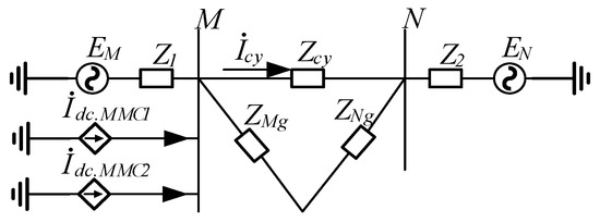
Figure 16.
Equivalent impedance network of fault system in multi-infeed system.
According to impedance transformation, Equations (24) and (25) can be obtained:
where in Equation (25) is the load current after DC input. Using Equation (22) to Equation (25), Equation (26) can be obtained:
In order to suppress the interference of DC feed-in on the differential quantity and eliminate the masking effect of load current in the braking quantity, this paper adopts the following strategy: remove the MMC injection current on the M side, add the DC system fault component on the N side, and subtract the load current when constructing the new braking quantity. The modified action quantity, braking quantity, and protection criterion are as follows:
where K is the braking coefficient, which is taken as 0.7 in this paper. The improved Id3 and Ir3 are applied in the main judgment criteria.
In summary, the differential current required on the M side is ( − ); that is, the differential current required on the N side is ( + ).
4.2. Voltage Criterion
In multi-infeed systems, one of the main problems facing differential protection is the differential current offset caused by converter injection, which is especially obvious in MMC hybrid systems. The sensitivity of the current criterion decreases in high-resistance faults. At this time, the introduction of voltage disturbance as auxiliary information will help to further improve the protection stability of the multi-infeed system.
When a fault occurs, the bus voltage at both ends of the protection zone will undergo a sudden change, and its mutation direction and amplitude are closely related to the fault location. In high-resistance faults, the differential current response is weak, but due to the sudden drop in the potential at the fault point, a significant voltage mutation will still be formed at the bus end, especially on the flexible converter side. In order to enhance the protection’s ability to identify weak current faults such as high-resistance grounding, a voltage auxiliary criterion is introduced as a redundant trigger condition. The criterion is based on the difference in the change in the modulus of the three-phase voltage on both sides of the bus M/N. The mean modulus of the amplitude before and after the fault is extracted through a sliding window, multiplied by the fault type sensitivity coefficient kvolt, and compared with the voltage threshold K to determine whether it is abnormal. The equation is as follows:
where UM(t) and UN(t) are the current mode lengths, and and are the average values of the three-phase mode lengths on the M/N side in the previous data window.
Combined with the judgment result of the differential current main criterion |−| > K( + ), the voltage auxiliary threshold K is set to construct the parallel criterion as follows:
where K is the voltage change threshold, which needs to be selected through simulation statistics and is generally selected in the range of 1.5~3 kV.
This section focuses on the failure of traditional current criteria under high-resistance grounding faults, and proposes a dual-criteria strategy consisting of an improved differential criterion and non-current auxiliary quantities. By introducing current injection compensation and bus voltage disturbance extraction mechanisms, the protection system’s response capability and error tolerance to weak faults are effectively improved, providing a basis for subsequent simulation verification.
5. Simulation Verification and Performance Evaluation of Dual-Criteria Strategy for Differential Protection
In order to further verify the effectiveness and robustness of the dual-criteria differential protection strategy proposed in Section 4 in the actual system, this paper designs and builds a simulation model of the LCC-MMC hybrid multi-feed system based on MATLAB R2022b. By setting various working conditions, such as typical in-zone faults, out-of-zone disturbances, and high-resistance grounding, the performance of the main and auxiliary criteria in fault identification, false operation suppression, and parameter sensitivity is systematically evaluated to verify the engineering applicability and criterion stability of the strategy under complex working conditions. Figure 17 presents a flowchart of the improved new dual-criteria protection scheme.
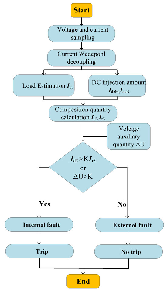
Figure 17.
New protection method process.
5.1. Simulation Verification and Performance Evaluation
Figure 18 provides a simulation diagram of the current and voltage criteria in the A-phase metal grounding fault scenario. The differential current criterion rapidly increases after the fault occurs, showing strong sensitivity and action speed, and can effectively identify single-phase grounding anomalies. In terms of the voltage criterion, due to the fault, the voltages on both sides of bus M and bus N on phase A are quite different, and the difference is significant, so the voltage auxiliary criterion also has good response capability. Both voltage and dual-current criteria can accurately identify this type of fault, reflecting good coordination and redundancy.
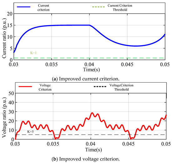
Figure 18.
Metal ground fault in phase A of multi-infeed system.
As shown in Figure 19, in the A-phase high-resistance grounding scenario, the improved current criterion shown in Figure 19a is always higher than the current criterion, showing strong sensitivity and action speed, and is not affected by high impedance, with sufficient differential characteristics and fast identification capabilities. The voltage criterion (Figure 19b) fluctuates significantly and crosses the threshold many times, and the auxiliary criterion is also effective. Overall, this combination has good reliability in medium- and high-resistance grounding scenarios.
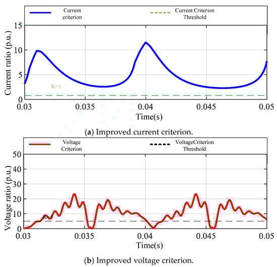
Figure 19.
Phase A high-resistance ground fault in a multi-infeed system.
As shown in Figure 20, in typical faults with strong symmetry, such as three-phase short circuits, although the system voltage drops significantly due to the synchronous changes on both sides of M/N, the traditional auxiliary criterion based on voltage differences may not respond sufficiently or even runs the risk of false suppression. However, the differential current is enhanced due to the strong current impact at the fault point, and the criterion is clearly higher than the threshold, with good action abilities. Therefore, even if the voltage criterion fails in this scenario, the overall protection can still rely on the main criterion for accurate identification and fault isolation. This reflects the redundancy advantage of the dual-criterion design, and stable protection can be achieved without all criteria being met at the same time.
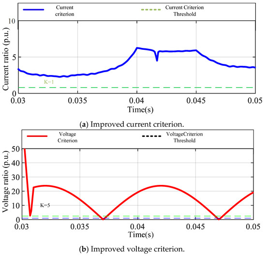
Figure 20.
Three-phase interphase fault in multi-infeed system.
As shown in Figure 21, in the out-of-zone fault scenario, the differential current criterion showed good selectivity, maintained a low level overall, and did not trigger protection action. Although the voltage criterion fluctuated slightly at certain moments, the overall amplitude did not exceed the threshold and did not cause false operation, indicating that it has a certain anti-interference ability. Under the current threshold configuration and criterion combination strategy, the voltage criterion remains stable in this type of out-of-zone fault, verifying its operational robustness against an interference background.
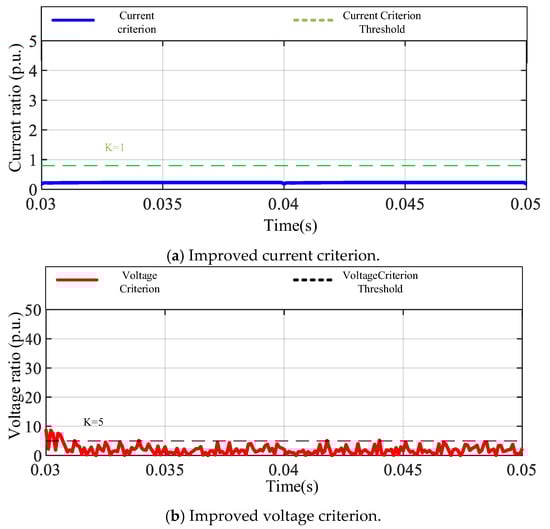
Figure 21.
External fault in multi-infeed systems.
Through the simulation analysis of different typical fault conditions, it can be seen that the differential current and voltage criteria have obvious complementarity in their response characteristics. The differential current criterion is highly sensitive to changes in fault current amplitude and is suitable for identifying high-impact faults such as three-phase short circuits and low-resistance grounding, while the voltage criterion provides auxiliary supplements in situations where the differential current response is not obvious, such as high-resistance grounding and minor faults. The coordinated use of the two can, on the one hand, improve sensitivity and ensure action under high-resistance faults; on the other hand, it can enhance the false operation-suppression capability through cross-validation and improve the selectivity and robustness of the protection system. The simulation results verify that the dual-criterion mechanism has high practical value and engineering feasibility in multi-feed hybrid systems.
5.2. Benchmarking with Related Protection Schemes
To place the proposed scheme in context, we benchmarked it against representative protection methods for hybrid LCC/MMC HVDC or MTDC–AC interfaced grids. Table 4 compares operating principle, reported/claimed time, and key strengths/limitations.
Table 4.
Comparison with related protection schemes.
Pilot voltage-differential protection on DC lines is fast and simple but relies on synchronized terminal quantities and a communication link, and can provide accurate fault sectioning and distance estimations [4]. A non-unit, ultra-high-speed traveling-wave scheme based on the first-peak time was validated on a real-project RTDS testbed and remains effective even at 500 Ω fault resistance [8]. For DC lines, a fast current-differential method using a frequency-dependent distributed parameter model achieves internal-fault detection within ~3 ms at relatively low sampling rates [11]. On AC lines connected to MMC-HVDC, an enhanced current-differential protection, improves sensitivity and security on a modified IEEE-39-bus benchmark [12]. For the receiving-end AC system of LCC-HVDC, Tellegen-theorem-based pilot criteria help maintain selectivity under commutation-failure-induced distortions [21]. Our dual-criteria scheme complements these methods by improving high-resistance sensitivity while maintaining external-fault security (cf. Figure 19a and Figure 21).
6. Discussion
The simulation results in Section 5 demonstrate that the proposed dual-criteria protection method significantly improves sensitivity under high-resistance grounding faults and maintains selectivity under external faults. Compared with conventional current differential protection, the improvements mainly derive from (1) the removal of DC feed-in disturbance from the differential quantity and (2) the use of bus voltage change rate as an auxiliary trigger in weak current fault scenarios.
In terms of applicability, the method is tailored for AC line protection in hybrid multi-infeed DC systems and is not directly applicable to pure DC networks. However, it can be extended to AC/DC hybrid microgrids by adding DC-side criteria and re-calibrating thresholds.
From an implementation perspective, precise time synchronization and sufficient sampling rates are essential to ensure accurate current and voltage measurements. Parameter settings, especially thresholds K and Kv, should be tuned according to the specific system configuration.
Future work will include validating the scheme on standard IEEE test systems (such as IEEE 14-bus and IEEE 39-bus) with added DC parts, and integrating dedicated DC-side protection criteria for unified AC/DC grid protection.
7. Conclusions
This paper proposes a dual-criteria differential protection strategy, which shows good adaptability and robustness in multi-infeed LCC-MMC hybrid DC systems. The current criterion has a highly sensitive response to strong fault current characteristics, especially in metallic grounding and phase-to-phase short-circuit faults, which can achieve rapid identification, while the voltage-assisted criterion provides effective compensation and enhancement in scenarios where the current response is not obvious, such as high-resistance grounding and metallic grounding faults. The two work together to not only expand the protection coverage but also effectively improve the ability to suppress refusal and false operation. The actual simulation results show that the dual-criteria structure has stable action characteristics under different fault types and interference backgrounds, achieving a comprehensive balance of sensitivity, selectivity, and anti-interference.
Author Contributions
Conceptualization, methodology, and writing—original draft preparation, Y.Z.; validation and supervision, P.J.; investigation and formal analysis, W.S.; simulation modeling and visualization, H.Z. All authors have read and agreed to the published version of the manuscript.
Funding
This research received no external funding.
Institutional Review Board Statement
Not applicable.
Informed Consent Statement
Not applicable.
Data Availability Statement
The MATLAB R2022b/Simulink simulation models used in this study are available from the corresponding author upon reasonable request. All raw data supporting the findings are presented in the figures and tables within the manuscript.
Conflicts of Interest
Authors Panrun Jin and Wenqin Song are employed by the company Economic and Technical Research Institute of Gansu Electric Power Company. Author Huilei Zhao is employed by the company Henan Puyang Power Supply Company. The remaining authors declare that the research was conducted in the absence of any commercial or financial relationships that could be construed as a potential conflict of interest.
References
- Xu, J.; Xie, X.; Dong, W.; Yu, P.; Xing, J. Investigation of New Low-Frequency Oscillation Caused by Converter-Interfaced Generations with MMC-HVDC Transmission. IEEE Trans. Power Deliv. 2025, 40, 1067–1077. [Google Scholar] [CrossRef]
- Parsa, S.; Abbaszadeh, K. Innovative Fault Ride-Through Cell for Modular Multilevel Converters: Enhancing Voltage Level Generation and Protection in HVDC Systems. In Proceedings of the 2025 16th Power Electronics, Drive Systems, and Technologies Conference (PEDSTC), Tabriz, Iran, 2–6 February 2025; pp. 1–5. [Google Scholar] [CrossRef]
- Guo, C.; Zhao, W. Interaction Analysis Among Multiple Series-Parallel Connected LCC/MMC in Hybrid Cascaded HVDC System. IEEE Trans. Power Deliv. 2025, 40, 974–987. [Google Scholar] [CrossRef]
- Han, K.; Chen, Y.; Wen, M.; Ma, R. A Novel Pilot Protection Scheme Based on Differential Voltage for Hybrid LCC/MMC HVDC Transmission Lines. IEEE Trans. Power Deliv. 2024, 39, 1816–1826. [Google Scholar] [CrossRef]
- Liu, Z.; Gao, H.; Luo, S. Non-unit protection for long-distance LCC-HVDC transmission lines based on waveform characteristics of voltage travelling waves. Int. J. Electr. Power Energy Syst. 2023, 150, 109079. [Google Scholar] [CrossRef]
- Luo, S.; Dong, X.; Shi, S.; Wang, B. A non-unit protection principle based on travelling wave for HVDC transmission lines. In Proceedings of the 2015 50th International Universities Power Engineering Conference (UPEC), Stoke on Trent, UK, 1–7 September 2015; pp. 1–6. [Google Scholar] [CrossRef]
- Kaur, J.; Jayasooriya, M.; Iqbal, M.N.; Daniel, K.; Shabbir, N.; Peterson, K. Fault Detection and Protection Strategy for Multi-Terminal HVDC Grids Using Wavelet Analysis. Energies 2025, 18, 1147. [Google Scholar] [CrossRef]
- Zhang, C.; Huang, J.; Song, G.; Dong, X. Non-Unit Ultra-High-Speed Line Protection for Multi-Terminal Hybrid LCC/MMC HVDC System and Its Application Research. IEEE Trans. Power Deliv. 2021, 36, 2825–2838. [Google Scholar] [CrossRef]
- Lei, S.; Shu, H.; Li, Z.; Tian, X.; Wang, S. A protection method for LCC-VSC hybrid HVDC system based on boundary transient power direction. Int. J. Electr. Power Energy Syst. 2023, 151, 109138. [Google Scholar] [CrossRef]
- Tiwari, R.S.; Sharma, J.P.; Gupta, O.H.; Ahmed Abdullah Sufyan, M. Extension of pole differential current based relaying for bipolar LCC HVDC lines. Sci. Rep. 2025, 15, 16142. [Google Scholar] [CrossRef]
- Nie, Y.; Liu, Y.; Lu, D.; Xie, Y.; Zou, X.; Wang, H. A Fast and Sensitive Current Differential Protection for MMC-HVDC Lines. IEEE Trans. Ind. Electron. 2024, 71, 14988–15000. [Google Scholar] [CrossRef]
- Liang, Y.; Ren, Y.; He, W. An Enhanced Current Differential Protection for AC Transmission Lines Connecting MMC-HVDC Stations. IEEE Syst. J. 2023, 17, 892–903. [Google Scholar] [CrossRef]
- Wang, G.; Huang, M.; Bai, H.; Li, J.; Yao, R.; Wang, H.; Li, C. A Current Differential Protection Scheme for Distribution Networks with Inverter-Interfaced Distributed Generators Considering Delay Behaviors of Sequence Component Extractors. Electronics 2023, 12, 4727. [Google Scholar] [CrossRef]
- Wang, S.; Cao, H.; Liu, J.; Liu, J.; Chen, S. Improved Braking Criterion for Phasor Current Differential Protection Based on Sigmoid Function. In Proceedings of the 2023 5th International Conference on Power and Energy Technology (ICPET), Tianjin, China, 27–30 July 2023; pp. 1200–1206. [Google Scholar] [CrossRef]
- Fang, Y.; Qiu, Y.; Yu, W.; Chen, B.; Zhou, C.; Jin, C. Improved Scheme of Current Differential Protection for MMC-HVDC Connected to AC Power Grid. In Proceedings of the 2023 International Conference on Power System Technology (PowerCon), Jinan, China, 21–22 September 2023; pp. 1–4. [Google Scholar] [CrossRef]
- Zhou, B.; Han, J.; Li, J.; He, J.; Wei, Q.; Li, T. A novel differential current protection and fault pole identification method based on modulus value. In Proceedings of the China HVDC and Power Electronics Annual Meeting of CSEE (DCPE 2024), Tianjin, China, 28–30 October 2024; pp. 213–219. [Google Scholar] [CrossRef]
- Zhang, K.; Li, G.; Shi, S.; Liu, S.; Zhao, L.; Dong, X. Pilot protection for flexible DC distribution line based on fault current difference. In Proceedings of the 18th International Conference on Developments in Power System Protection (DPSP APAC 2025), Hong Kong, China, 8–11 January 2025; pp. 192–197. [Google Scholar] [CrossRef]
- Wang, Y.; Ouyang, J.; Shi, Z.; Fan, S. A Novel Non-Unit Protection Method for MMC-HVDC Transmission Lines Based on the Ratio of Line-Mode Voltage Second Derivative. Electricity 2024, 5, 826–842. [Google Scholar] [CrossRef]
- Chen, N.; Li, G.; Tang, D.; Ling, Y.; Wang, S.; Luo, Y. LCC-MMC HVDC Line Pilot Protection Based on U-Q Characteristic Curve. In Proceedings of the 2024 IEEE International Conference on DC Technologies and Systems (DCTS), Zhuhai, China, 19–20 October 2024; pp. 1–6. [Google Scholar] [CrossRef]
- He, Y.; Zheng, X.; Tai, N.; Wang, J.; Nadeem, M.H.; Liu, J. A DC Line Protection Scheme for MMC-Based DC Grids Based on AC/DC Transient Information. IEEE Trans. Power Deliv. 2020, 35, 2800–2811. [Google Scholar] [CrossRef]
- Fan, Y.; Gao, H.; Liu, Z.; Liu, N. A New Pilot Protection Based on Tellegen’s Theorem for Receiving-end AC Transmission Lines of LCC-HVDC Hybrid System. In Proceedings of the 2024 9th Asia Conference on Power and Electrical Engineering (ACPEE), Shanghai, China, 11–13 April 2024; pp. 251–255. [Google Scholar] [CrossRef]
- Piao, G.; Xiaodong, Z.; Chenxu, C.; Nengling, T.; Zengli, Y.; Jin, W. A Pilot Protection Scheme for MMC-HVDC Transmission Lines Based on Transient Energy. In Proceedings of the 2021 4th International Conference on Energy, Electrical and Power Engineering (CEEPE), Chongqing, China, 23–25 April 2021; pp. 738–743. [Google Scholar] [CrossRef]
- Yu, X.; Xiao, L. A DC Fault Protection Scheme for MMC-HVDC Grids Using New Directional Criterion. IEEE Trans. Power Deliv. 2021, 36, 441–451. [Google Scholar] [CrossRef]
- Li, Y.; Li, J.; Li, G.; Cao, R.; Zeng, X.; Tong, N. High-speed main protection for multiterminal LCC-MMC-UHVDC based on initial wave process comparison. IET Gener. Transm. Distrib. 2024, 18, 4302–4327. [Google Scholar] [CrossRef]
- Haro-Larrode, M.; Santos-Mugica, M.; Etxegarai, A.; Eguia, P. Methodology for Tuning MTDC Supervisory and Frequency-Response Control Systems at Terminal Level under Over-Frequency Events. Energies 2020, 13, 2807. [Google Scholar] [CrossRef]
- Du, H.; Hashfi, T.B.; Prasad, R.; Vergara, P.P.; Palensky, P.; Lekić, A. Optimal Droop Control Strategy for Coordinated Voltage Regulation and Power Sharing in Hybrid AC-MTDC Systems. arXiv 2025, arXiv:2505.03651. [Google Scholar] [CrossRef]
- Sun, J.; Debnath, S.; Bloch, M.; Saeedifard, M. A Hybrid DC Fault Primary Protection Algorithm for Multi-Terminal HVdc Systems. IEEE Trans. Power Deliv. 2021, 37, 1285–1294. [Google Scholar] [CrossRef]
- Gaballah, A.; Abu-Elanien, A.E.B.; Megahed, A.I. A Decision Tree Based Ultra-high-speed Protection Scheme for Meshed MMC-MTDC Grids with Hybrid Lines. J. Electr. Eng. Technol. 2024, 19, 887–900. [Google Scholar] [CrossRef]
- Muniappan, M. A comprehensive review of DC fault protection methods in HVDC transmission systems. Prot Control. Mod Power Syst 2021, 6, 1. [Google Scholar] [CrossRef]
- Ramirez, A.; Semlyen, A.; Iravani, R. Order reduction of the dynamic model of a linear weakly periodic system—Part II: Frequency-dependent lines. IEEE Trans. Power Syst. 2004, 19, 866–871. [Google Scholar] [CrossRef]
- Gustavsen, B. Time delay identification for transmission line modeling. In Proceedings of the 8th IEEE Workshop Signal Propagation on Interconnects, Heidelberg, Germany, 9–12 May 2004; pp. 103–106. [Google Scholar]
- De Silva, H.M.J.; Gole, A.M.; Wedepohl, L.M. Accurate electromagnetic transient simulations of HVDC cables and overhead transmission lines. In Proceedings of the International Conference on Power Systems. Transients (IPST’07), Lyon, France, 4–7 June 2007. Paper 07IPST024. [Google Scholar]
Disclaimer/Publisher’s Note: The statements, opinions and data contained in all publications are solely those of the individual author(s) and contributor(s) and not of MDPI and/or the editor(s). MDPI and/or the editor(s) disclaim responsibility for any injury to people or property resulting from any ideas, methods, instructions or products referred to in the content. |
© 2025 by the authors. Licensee MDPI, Basel, Switzerland. This article is an open access article distributed under the terms and conditions of the Creative Commons Attribution (CC BY) license (https://creativecommons.org/licenses/by/4.0/).