1. Introduction
Robots are rapidly increasing in many parts of modern life, from the manufacturing industry and healthcare to exploration. Robots can be divided into two main categories: flexible and rigid. Rigid robots are constructed of hard materials like metals or plastics, and their mechanical designs limit their motions [
1,
2]. Moreover, due to their rigid structures, they are limited to working in confined spaces and need special modifications to meet the flexibility requirements for many precise applications, such as minimally invasive surgery. Rigid robots have constraints in flexibility, especially when performing operations on internal organs, since it is quite difficult to access the circuitous parts of the human body. These limitations can be overcome by using flexible robots, which solve this problem. Continuum robots adjust their shape at any point along their length, enabling them to function or operate in confined areas and complex environments inaccessible to traditional rigid link robots. Continuum robots are under-actuated systems where degrees of freedom (DOF) can be varied based on design and actuation mechanisms [
3,
4]. Continuum robots are broadly categorized into three types: tendon-driven continuum manipulators (TCMs), tendon-driven serpentine manipulators (TSMs), and concentric tube manipulators (CTMs). A detailed description of them can be found in [
5].
Tendon-driven continuum robots are actuated from the base. Upon increasing the number of tendons/cables, the DOF of a continuum robot can be varied [
6,
7]. As DOF are variable and do not consist of links and joints, D-H parameters to solve kinematics are not applicable; hence, the mathematical modeling of continuum robot kinematics is complex [
8]. Researchers have developed many models of continuum robots based on their applications [
9,
10]. The kinematics of continuum robots depends on their design considerations [
11]. A method to derive kinematics has been developed by assuming constant curvature bending [
12,
13]. Many designs have been proposed [
14,
15,
16] to model continuum robots, considering their applications in many fields. Experimental validations have been done assuming a constant curvature approach [
17]. Different methods to derive constant curvature kinematics have been discussed and compared [
18]. It was stated that a smaller diameter-length ratio is required in minimally invasive surgeries to follow torturous paths [
19]. Workspace analysis of TCMs and CTMs has been compared by researchers [
5]. Material selection and various actuation methods have been described to actuate the continuum robots [
20]. Necessary tests are needed to find the bending, deformation capabilities, tip position tracking, workspace analysis, and actuation mechanism for enhanced use in confined space explorations and surgical applications [
21].
The advantage of choosing cable/tendon-driven continuum robots rather than concentric tube manipulators is that they adhere to the design [
22]. Concentric tube robots, often formed of super-elastic nitinol (NiTi) tubes, comprise several nested pre-curved tubes. The tubes are overlapped to create CTMs. The translation and rotation of each tube control the position and orientation of the distal end [
23,
24,
25]. The discussion above summarizes that the continuum robot should have the following features:
It should bend in any direction.
It should be as small as possible for medical pipe inspection applications to explore confined and contour environments during its operation.
The backbone material should be strong and flexible enough for structural rigidity.
Overall, the structure should be flexible enough to achieve a compliant mechanism.
Many studies have been conducted that aim to create the best designs that are feasible and suitable for applications including medical, search, and rescue operations due to their compliance, flexibility, dexterity, and adaptability to confined spaces and environments. The realization of DOFs and kinematics is also necessary.
2. Literature Study
Several researchers have proposed many designs and methods to solve the kinematics of tendon-driven continuum robots for different applications. The background study performed in this research mainly focused on two aspects: design, the kinematics of continuum robots, and the research gap.
2.1. Design
The number of DOF of a continuum robot can be varied based on designs and actuation mechanisms. Several studies have proposed many designs to model tendon-driven continuum robots for different applications. Ouyang et al. in 2016 developed a design consisting of a three-segment continuum robot for minimally invasive surgery. The continuum robot design employs a single super-elastic nitinol rod as the backbone and concentric disks assembled on the backbone for the tendon attachment [
14]. Li et al. in 2017 designed a novel tendon-driven continuum robot with two modules/segments and a compliant/flexible backbone formed by helical springs. In this design, each module is driven by four parallel arranged tendons to implement a redundant actuation mechanism that gives dexterous motions to the robot [
15]. Castledine et al. in 2019 proposed a design consisting of a flexible core combined with rigid interlocking vertebrae evenly distributed along its length. This design allows bending in two DOF while minimizing torsional movement. The proposed design segment is actuated by two antagonistic tendon pairs (one pair contracts and the other pair relaxes or lengthens). This design also features a large hollow central bore, which could be used for suction-assisted gripping of objects [
16].
2.2. Kinematics
Several approaches to derive the kinematics of a tendon-driven continuum robot using several tendons in the design are available in the literature. Jones et al. in 2006 coined a concept in which they fit a conceptual conventional rigid link manipulator to the continuum backbone of a continuum robot [
12]. Mosqueda et al. in 2018 derived kinematics using a constant curvature bending approach for three-tendon-driven actuations. The continuum robot developed has one segment with seven sections, each driven by three cables/tendons [
17]. Bhattacherjee et al. in 2018 derived the kinematics of a continuum robot driven by four tendons that are 90° apart. The kinematics was solved by taking the parameters of the bent section (primary backbone) and corresponding tendons of the section [
26]. Wu et al. in 2022 proposed a new geometric approach to solve the IK of the continuum robot consisting of two segments [
27].
2.3. Research Gap
It is evident that a continuum robot with variable-length behavior has yet to be developed, which is our main objective. A constant curvature kinematic approach [
12] will be followed in this research to solve the kinematics of the continuum robot. Two stepper motors will drive four tendons, making the continuum robot an under-actuated system. The proposed designs so far from the literature study include either tendons for the actuation of the continuum robot [
12,
14,
16,
17] or springs [
15] for creating the backbone structure of the continuum robot with structural rigidity [
28,
29]. Minimal work was done using both tendons and springs for modeling the continuum robots, and the same can be justified from the literature.
3. Methodology
The current research focuses on developing a tendon-driven continuum robot driven by four tendons 90° apart due to their symmetry in architecture, and it has added advantages over three-tendon-driven continuum robots in terms of design, kinematics, and actuation. An under-actuation system drives the tendons of the robot. First, the kinematics of the robot are solved using the constant curvature approach [
12]. Then, the design of the robot is carried out, considering all the components necessary to build the model, including mathematical modeling. The structural members are manufactured using digital light processing (DLP) 3D printing. Testing is carried out once prototyping is done by integrating the actuation system into the structural members of the robot. The overall workflow of this research is represented in
Figure 1.
3.1. Kinematics
3.1.1. Forward Kinematics
Deriving the kinematics of a continuum using D-H parameters will not provide a solution for this research. An assumption is made that the continuum robot follows constant curvature bending to derive the kinematics, which contradicts practical implementations, as the load varies from the end to the base structure, thereby leading to a non-linear distribution of the load. Studies have also proposed various methods to derive the kinematics of continuum robots [
12,
17,
18,
26], as mentioned in the previous section. The kinematics of a continuum robot can be developed by considering a bent section [
15].
The bent section, as shown in
Figure 2, creates an arc of length (
s) with curvature (
k), making an angle (
Φ). The kinematic mapping from the actuation space to the task space can be decomposed into two parts, which map from the actuator lengths ([
l1l2l3l4]
T) to the arc parameters (
s,
k,
Φ), and from the arc parameters to the robot tip position
. The mapping from the actuator lengths to the arc parameters for a bent section is given by following
Table 1.
The homogeneous transformation matrix (A) of the 4-tendon-driven continuum robot gives the forward kinematics and can be referred from Equation (4) below. Here, the 3 × 3 matrix from A represents the orientation of the tip, and the 3 × 1 vector from A represents the position of the tip.
The kinematic simulation was performed using OCTAVE software (version 9.3.0).
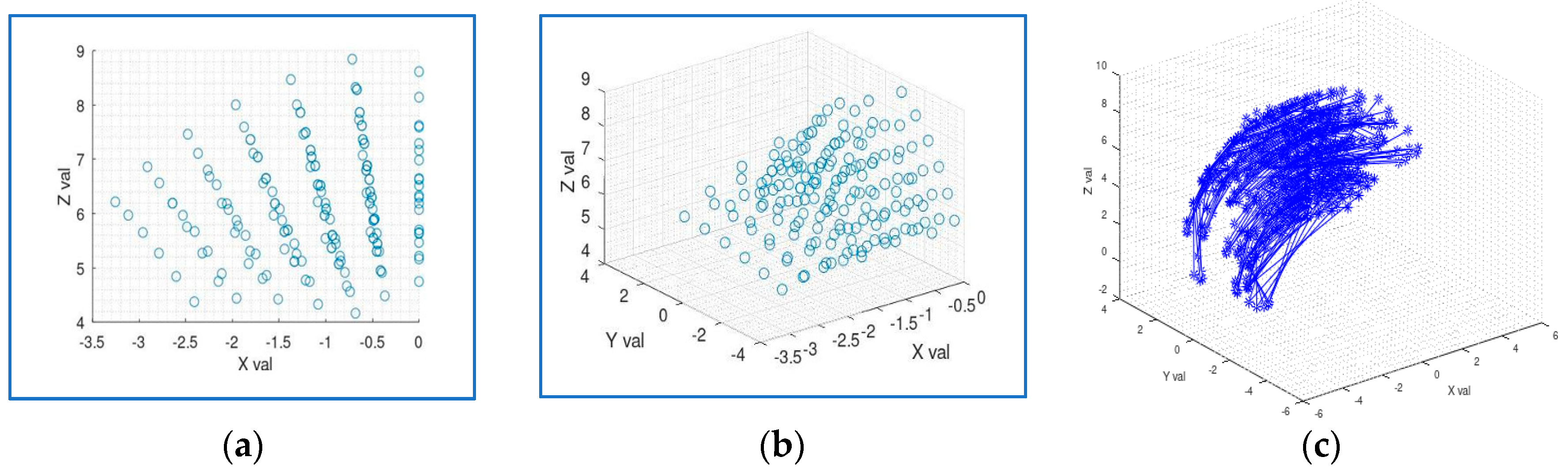
Figure 3a indicates the tip position in the XZ plane. The same representation in the 3D XYZ plane is indicated in
Figure 3b below.
Figure 3c shows the continuum robot’s tip coordinates (x, y, z) for all bent sections with varying tendon lengths, which gives the visualization of the robot’s workspace.
3.1.2. Inverse Kinematics
The inverse kinematics of a continuum robot driven by four tendons are obtained by mapping the lengths of the tendons of a bent segment to the arc parameters. The equations to find the tendon lengths in terms of arc parameters will differ by 90° between
l1l2l3 and
l4, since all four tendons are arranged 90° apart.
where
n is the number of disks considered = 10 for this research, and
d = 3.6 mm (distance from tendon to continuum backbone).
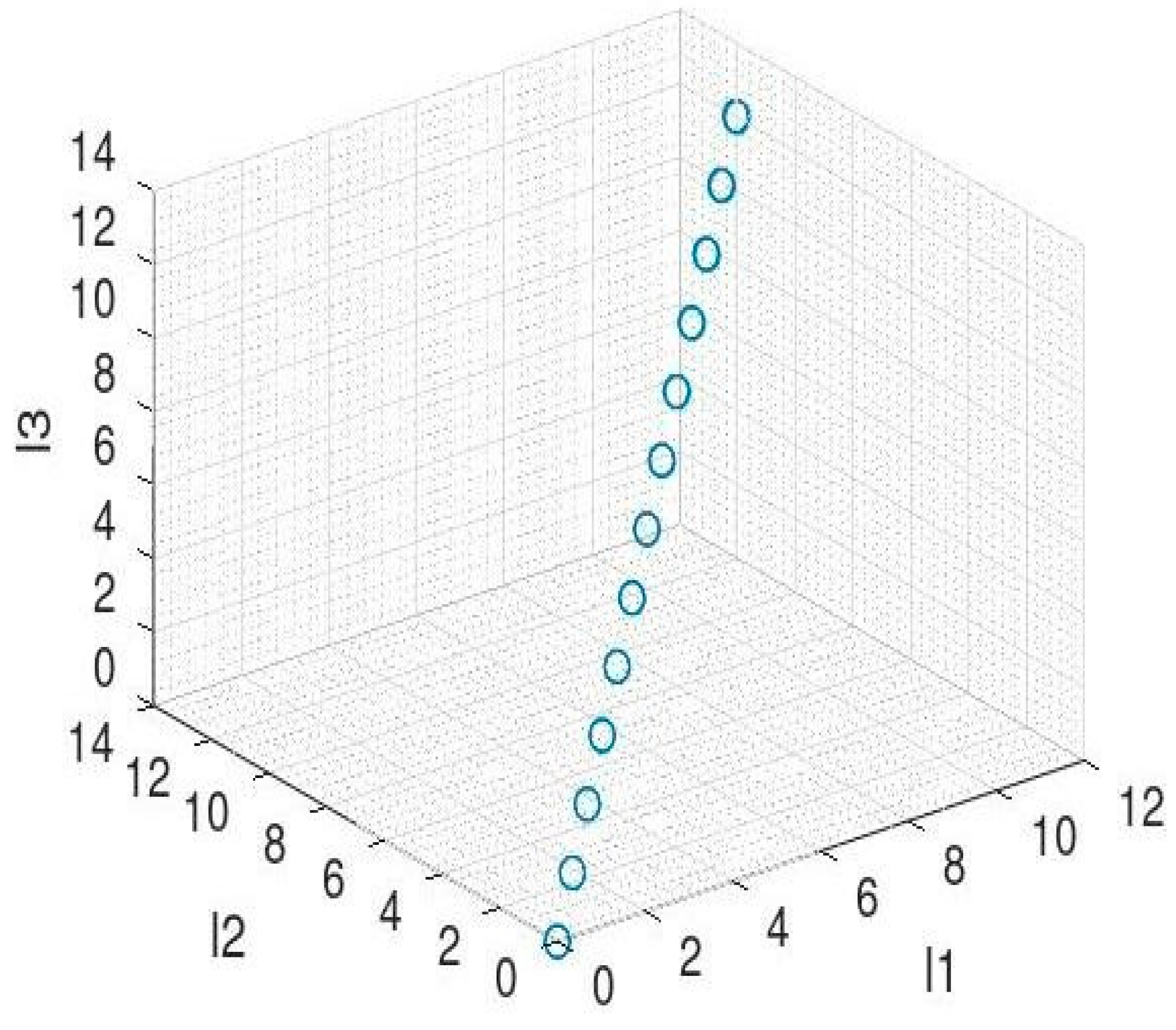
Figure 4 maps the arc parameters (s, k,
Φ) to the tendon lengths (
l1,
l2,
l3,
l4). This gives the inverse kinematics by using Equations (5)–(8).
3.2. Kinematic Validation
Kinematic validation is also performed for both the forward and inverse kinematics of a 4-tendon-driven continuum robot. To validate the forward kinematics for a particular bent section, the lengths of tendons [
l1,
l2,
l3,
l4] are found to be [
5,
17,
19,
30], the arc parameters are calculated (
s,
k,
Φ) = (0.1098, 8.0026, 0.3218) and the end position coordinates (
x,
y,
z) = (−3.1263, −1.0421, 7.0118) are found. A similar approach is followed to validate the inverse kinematics by taking the arc parameters (
s,
k,
Φ) to be (0.1098, 8.0026, 0.3218) of a particular bent section and calculating the lengths of the tendons [
l1l2l3l4] = [5.0001, 6.9999, 11, 9.0002] for the above-derived end position coordinates. A note is made that at a particular bending angle, the lengths of the tendons become [
l1l2l3l4] = [9.9998, 9.9998, 10.9998, 10.9998].
l1 = l2; l3 = l4 when the robot bends with 45°.
3.3. Design
In this study, many designs are explored [
14,
15,
16,
30,
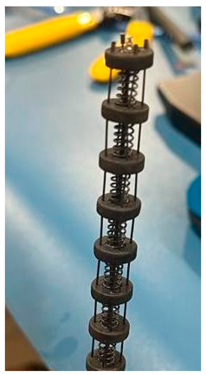
31] to model a continuum robot with a very small form factor suitable for confined space explorations. The developed design, as shown in
Figure 5, includes structural members like disks, backbone, tendons, and springs responsible for the change in the robot’s shape under actuation. The use of springs in the design will help the continuum robot to achieve contraction along its length. A provision in the disk has been given for the spring to sit on the disk. The main goal is to design a continuum robot driven by four tendons that are 90° apart. So, a guide for each tendon is provided on the disks, along with a central guide for the backbone member. Provision for springs is given on the top and bottom faces of the disks.
The reason for this small dimension is for the robot to be used in surgical applications. Once disks are designed, springs are added to the design. The number of disks considered is limited to 10 in the design, and nine springs will accommodate the disks. A backbone design member and tendons are attached to the design. The guides provided in the disks for the tendons and backbone maintain clearance, enabling them to route easily. A base plate is also designed to let the continuum robot’s distal end sit on it. The final assembly achieved can be referred to in
Figure 6.
All four tendons and the continuum backbone are crimped at the face of the top disk using an rj45 crimping tool, restricting them from sliding through their respective guides. The tendons are routed from the distal end to the proximal end for actuation.
3.4. Prototype Development
The 4-tendon-driven CR model has tendons arranged 90° apart, allowing two tendons to be in a horizontal direction (x-axis) and the other two in a vertical direction (y-axis). This configuration allows the opposite tendons to act as antagonistic pairs to achieve pitch and yaw-bending motions. All the components necessary to build the prototype of a 4-tendon-driven continuum robot were manufactured using DLP 3D printing (disks and base plate) and procured (compression springs, tendons, and NiTi backbone). The components include disks, springs, the continuum backbone, tendons, and the actuation unit at the proximal end. Two NEMA-17 stepper motors actuate four tendons. Motor drives for both stepper motors are connected, and the proximal module is controlled by Arduino UNO and run by a 12 V DC power supply.
Development of the prototype involves two stages:
Distal end;
Proximal module.
3.4.1. Distal End Development
The distal end of the developed continuum robot consists of an assembly of disks, springs, tendons, and a backbone, as shown in
Figure 7. All four tendons and backbone are crimped on the face of the top disk to restrict their sliding through their respective guide holes, as mentioned in
Section 2. All the components of the distal end are assembled carefully and crimped. An identical distance is maintained between each disk because of the spring, which means that all disks are equidistant along the length of the continuum backbone.
3.4.2. Proximal Module
The proximal module contains the actuation unit that actuates the continuum robot. The actuation unit includes 2 Nema-17 stepper motors, 2 L298N motor drivers, an Arduino UNO controller, and splice connectors. Necessary connections are given between all electronic components in the proximal module to actuate the distal end.
The built proximal module is integrated with the distal end, and the continuum robot prototype is built, as shown in
Figure 8. Before connecting, the tendons are categorized into two pairs. Each pair has opposite-faced wires, making each pair responsible for bending in the respective direction. This is often referred to as an antagonistic pair of tendons. This arrangement allows the distal end of the prototyped continuum robot to bend in pitch (
y-axis) and yaw (
x-axis). Also, using springs in the distal end enables it to contract along its length, giving 3 DOF to the developed continuum robot.
3.5. Materials
The use of super-elastic nitinol for the backbone and tendons provides flexibility to the robot. Nitinol is biocompatible as it does not harm human tissue [
32] when used in building this robot for surgical applications. A practical application of nitinol is its use in stents for cardiovascular surgeries. Stainless steel 304 compressive springs are used. SS304 is known for its excellent low carbon content and high corrosion resistance, making it suitable for use in medical applications.
4. Testing
After building the prototype, the continuum robot is tested to check its bending capabilities. The testing of the continuum robot is carried out by connecting a 12 V power supply to the proximal module of the continuum robot to run both stepper motors, which in turn actuate the distal end, allowing it to bend in both the pitch and yaw directions and contract along its length.
Testing has been carried out to find the following:
Both stepper motors are coded in a way that they rotate two revolutions in both the clockwise and counterclockwise directions. Based on motor control, the continuum robot’s bending can be achieved along with its distal end’s length contraction.
4.1. Pitch Motion
Bending in the pitch axis is achieved by connecting a pair of tendons to one stepper motor. To measure the bending angle, graph paper is placed behind the distal end, taking the vertical axis as a reference for bending. The tendon pair is wound on the motor shaft in the opposite direction, making them an antagonistic pair. When the motor rotates, one tendon gets wound, and the other tendon gets unwound, achieving bending.
To achieve negative pitch, motor 1 is made to rotate clockwise for two revolutions, allowing the distal end to bend. The bending angle is measured from the base of the vertical axis to the tip of the continuum backbone and is represented in
Figure 9a,b. To achieve a positive pitch, the same motor is made to rotate anti-clockwise for two revolutions, and the corresponding bending angle is measured in the positive pitch axis, represented by
Figure 9c.
The bending achieved in the positive pitch is equal to the bending achieved in the negative pitch due to the prototype’s symmetry in the pitch axis.
4.2. Yaw Motion
When the motor is made to rotate counterclockwise, the tendon that is wound on the shaft gets pulled, and this bends the robot in a negative yaw direction, as shown in
Figure 10a. The same way is used to measure the bending angle in the yaw axis, as shown in
Figure 10b.
To achieve a positive yaw, the same motor is made to rotate clockwise for two revolutions, and the corresponding bending angle is measured in the positive yaw axis, as shown in
Figure 10c. The bending achieved in both the positive and negative yaw axes is the same due to the model’s symmetry in the yaw axis.
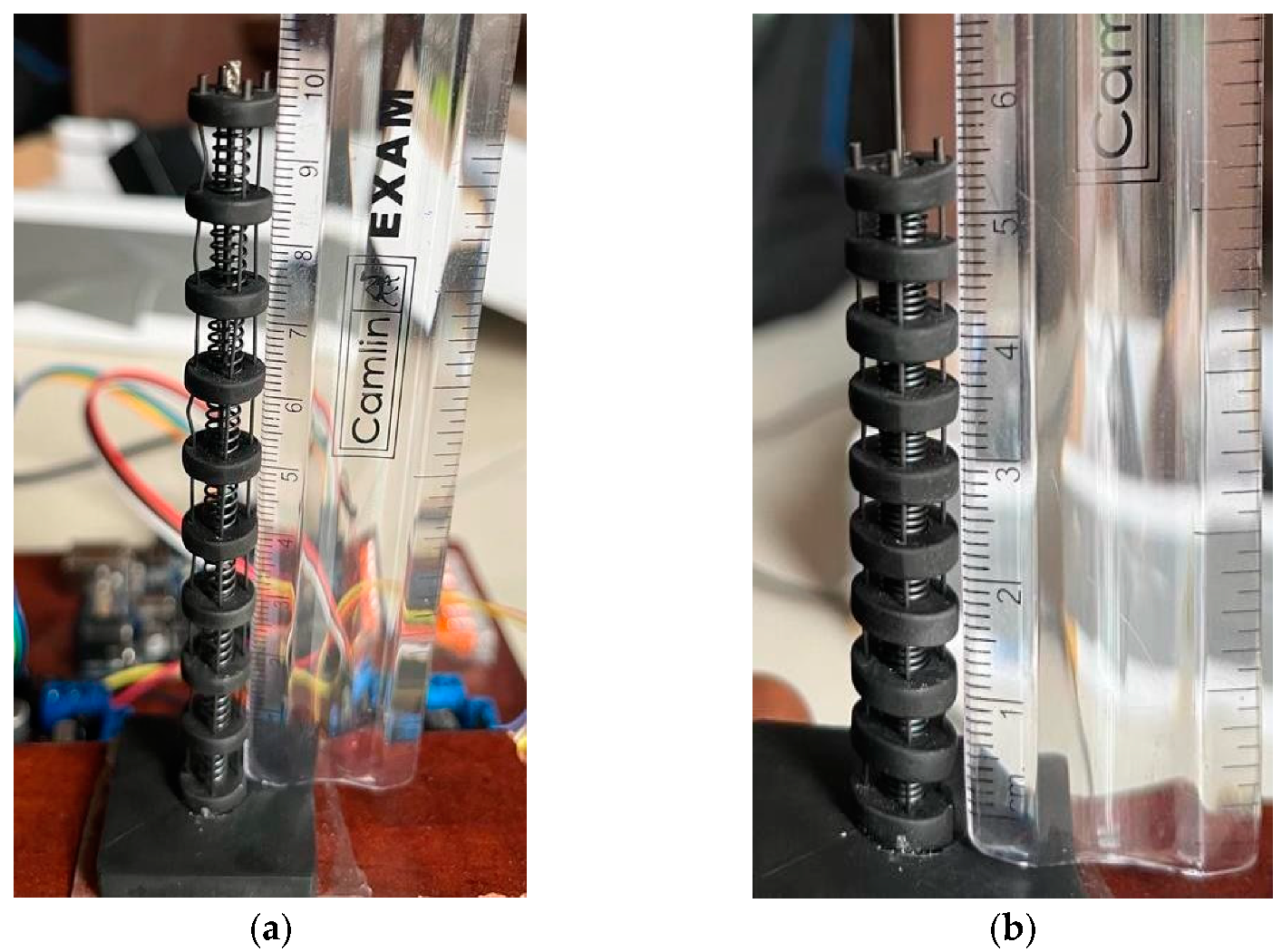
4.3. Contraction
A change in the length of the distal end is achieved by operating both motors simultaneously in directions opposite to each other. The use of compression springs in the prototype enables the distal end to compress along its length by pulling all four tendons. The initial length of the continuum robot’s distal end is calculated manually under no actuation condition. Then, the motors are made to run, which pulls the tendons by exerting force on the springs, allowing them to compress, resulting in overall contraction of the distal end. The percentage change in length is found to be 46%. The lengths of the robot before and after actuation are represented in
Figure 11a and
Figure 11b, respectively.
5. Results and Discussion
After testing the bending capabilities and contraction length of the developed prototype, the following is found:
Bending in yaw direction = ±45°;
Bending in pitch direction = ±42°;
Max. contraction in length = 46%.
Necessary relations are developed to relate to the motor rotation, pull in tendon length, and bending angles, and the values are tabulated in
Table 2.
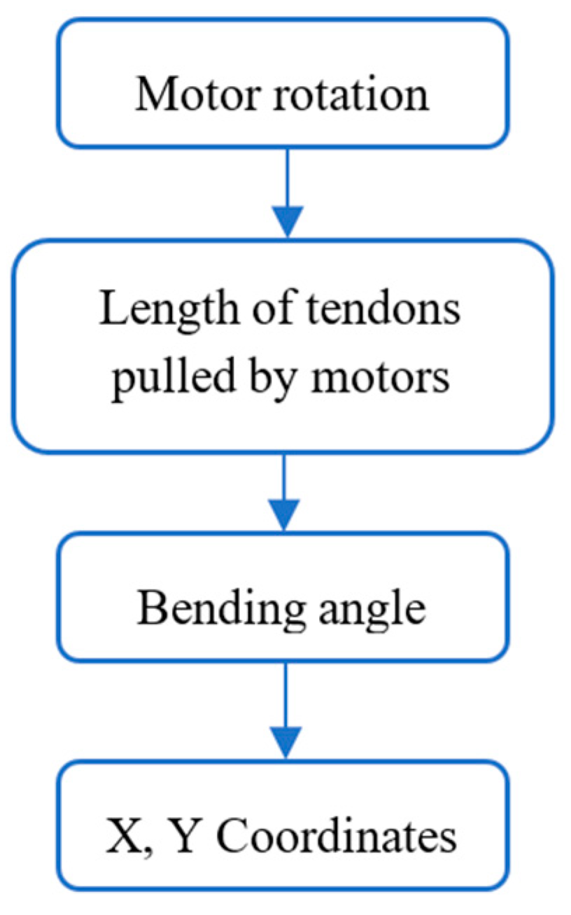
It can be said that if the motor rotates 720° (400 steps), this rotation will pull the tendons by 75.36 mm, resulting in a 45° bending of the continuum robot’s distal end. The same follows for the remaining tabular values. It represents the relation between the bending angles and tip positions of the continuum robot. The tip coordinates of the continuum robot in a 2D plane are given by the following:
where
l = the length of the arc when the robot is bent and
= the bending angle.
The main relation to finding the tip coordinates of the distal end from the proximal module is given in a flow, as shown in
Figure 12.
The arc lengths of the continuum robot bent section for the corresponding bending angles are tabulated in
Table 3.
The tip coordinates are measured using Equations (10) and (11) and are tabulated for the corresponding angles given in
Table 4.
Figure 13 shows the relation between the tip coordinates of the continuum robot’s distal end for the corresponding bending angles.
6. Conclusions
In this research, a single-module tendon-driven continuum robot has been developed. The use of super-elastic nitinol as the backbone provided the bending capabilities, giving a 45° bending angle to the distal end, allowing it to interact with unstructured environments. From the experiments, it is evident that the developed continuum robot achieved three DOF. Also, it can be said that the developed tendon-driven continuum robot bends with a constant curvature and has symmetric bending in both the pitch and yaw directions. Mathematical modeling of the kinematics was derived for fa our-tendon-driven continuum robot, and the results comply with each other in terms of tip positions. Deformation has been achieved with 46% contraction of the distal end along its length.
7. Future Scope
Programming can be performed to solve the kinematics, path planning of the continuum robot, and its control in minimally invasive surgical procedures. Sensors like flex sensors to measure the bending and optical sensors to track the tip positions of the continuum robot can be used to receive feedback for better closed-loop control. As for the under-actuated system, DC servo motors could offer advantages such as smoother motion and higher torque. Hence, DC servo motors can be employed in place of stepper motors for enhanced accuracy and precise control because of their feedback nature.
Author Contributions
Conceptualization, N.Y.S.S.; Methodology, P.K. and S.M.; Software, P.K.; Validation, P.K.; Formal analysis, N.Y.S.S.; Investigation, I.D.; Resources, I.D.; Data curation, I.D.; Writing—original draft, N.Y.S.S. and R.B.P.; Writing—review & editing, N.Y.S.S., P.K. and S.M.; Visualization, R.B.P.; Supervision, R.B.P. All authors have read and agreed to the published version of the manuscript.
Funding
This research received no external funding.
Institutional Review Board Statement
Not applicable.
Informed Consent Statement
Not applicable.
Data Availability Statement
The data presented in this study are available on request from the corresponding author. The data are not publicly available due to confidentiality.
Conflicts of Interest
The authors declare no conflict of interest.
References
- Neppalli, S.; Jones, B.A. Design, construction, and analysis of a continuum robot. In Proceedings of the 2007 IEEE/RSJ International Conference on Intelligent Robots and Systems, San Diego, CA, USA, 29 October–2 November 2007. [Google Scholar]
- Wu, H.; Yu, J.; Pan, J.; Ge, G.; Pei, X. A New Geometric Method for Solving the Inverse Kinematics of Two-Segment Continuum Robot. In Intelligent Robotics and Applications: 15th International Conference, ICIRA 2022, Harbin, China, 1–3 August 2022; Proceedings, Part II; Springer International Publishing: Cham, Switzerland, 2022. [Google Scholar]
- Zhong, Y.; Hu, L.; Xu, Y. Recent advances in design and actuation of continuum robots for medical applications. Actuators 2020, 9, 142. [Google Scholar] [CrossRef]
- da Veiga, T.; Chandler, J.H.; Lloyd, P.; Pittiglio, G.; Wilkinson, N.J.; Hoshiar, A.K.; Harris, R.A.; Valdastri, P. Challenges of continuum robots in the clinical context: A review. Prog. Biomed. Eng. 2020, 2, 032003. [Google Scholar] [CrossRef]
- Li, Z.; Wu, L.; Ren, H.; Yu, H. Kinematic comparison of surgical tendon-driven manipulators and concentric tube manipulators. Mech. Mach. Theory 2017, 107, 148–165. [Google Scholar] [CrossRef]
- Zhang, J.; Kan, Z.; Li, Y.; Wu, Z.; Wu, J.; Peng, H. Novel design of a cable-driven continuum robot with multiple motion patterns. IEEE Robot. Autom. Lett. 2022, 7, 6163–6170. [Google Scholar] [CrossRef]
- Tian, Y.; Luan, M.; Gao, X.; Wang, W.; Li, L. Kinematic analysis of continuum robot consisted of driven flexible rods. Math. Probl. Eng. 2016, 2016, 1–7. [Google Scholar] [CrossRef]
- Rao, P.; Peyron, Q.; Lilge, S.; Burgner-Kahrs, J. How to model tendon-driven continuum robots and benchmark modeling performance. Front. Robot. AI 2021, 7, 630245. [Google Scholar] [CrossRef]
- Kolachalama, S.; Lakshmanan, S. Continuum robots for manipulation applications: A survey. J. Robot. 2020, 2020, 4187048. [Google Scholar] [CrossRef]
- Zhang, G.; Du, F.; Xue, S.; Cheng, H.; Zhang, X.; Song, R.; Li, Y. Design and modeling of a bio-inspired compound continuum robot for minimally invasive surgery. Machines 2022, 10, 468. [Google Scholar] [CrossRef]
- Zhang, T.; Yang, L.; Yang, X.; Tan, R.; Lu, H.; Shen, Y.; Lu, H. Millimeter-scale soft continuum robots for large-angle and high-precision manipulation by hybrid actuation. Adv. Intell. Syst. 2021, 3, 2000189. [Google Scholar] [CrossRef]
- Jones, B.A.; Walker, I.D. Kinematics for multisection continuum robots. IEEE Trans. Robot. 2006, 22, 43–55. [Google Scholar] [CrossRef]
- Zhang, J.; Fang, Q.; Xiang, P.; Sun, D.; Xue, Y.; Jin, R.; Qiu, K.; Xiong, R.; Wang, Y.; Lu, H. A survey on design, actuation, modeling, and control of continuum robot. Cyborg Bionic Syst. 2022, 2022, 1–13. [Google Scholar] [CrossRef]
- Ouyang, B.; Liu, Y.; Sun, D. Design of a three-segment continuum robot for minimally invasive surgery. Robot. Biomim. 2016, 3, 1–4. [Google Scholar] [CrossRef] [PubMed]
- Li, M.; Kang, R.; Geng, S.; Guglielmino, E. Design and control of a tendon-driven continuum robot. Trans. Inst. Meas. Control. 2018, 40, 3263–3272. [Google Scholar] [CrossRef]
- Castledine, N.P.; Boyle, J.H.; Kim, J. Design of a modular continuum robot segment for use in a general purpose manipulator. In Proceedings of the 2019 International Conference on Robotics and Automation (ICRA), Montreal, QC, Canada, 20–24 May 2019. [Google Scholar]
- Mosqueda, S.; Linares, Y.M.; Murrugarra, C.; León-Rodriguez, H. Constant Curvature Kinematic Model Analysis and Experimental Validation for Tendon Driven Continuum Manipulators. In Proceedings of the 15th International Conference on Informatics in Control, Automation and Robotics, Porto, Portugal, 29–31 July 2018. [Google Scholar]
- Chawla, A.; Frazelle, C.; Walker, I. A comparison of constant curvature forward kinematics for multisection continuum manipulators. In Proceedings of the 2018 Second IEEE International Conference on Robotic Computing (IRC), Laguna Hills, CA, USA, 31 January–2 February 2018. [Google Scholar]
- Amanov, E.; Nguyen, T.-D.; Burgner-Kahrs, J. Tendon-driven continuum robots with extensible sections—A model-based evaluation of path-following motions. Int. J. Robot. Res. 2021, 40, 7–23. [Google Scholar] [CrossRef]
- Li, S.; Hao, G. Current Trends and Prospects in Compliant Continuum Robots: A Survey. Actuators 2021, 10, 145. [Google Scholar] [CrossRef]
- Seleem, I.A.; El-Hussieny, H.; Ishii, H. Recent developments of actuation mechanisms for continuum robots: A review. Int. J. Control Autom. Syst. 2023, 21, 1592–1609. [Google Scholar] [CrossRef] [PubMed]
- Tian, Y.; Yang, S.; Geng, H.; Wang, W.; Li, L. Kinematic modeling of the constant curvature continuum line drive robot. In Proceedings of the 2016 IEEE International Conference on Robotics and Biomimetics (ROBIO), Qingdao, China, 3–7 December 2016. [Google Scholar]
- Goldman, R.E.; Bajo, A.; Simaan, N. Compliant motion control for multisegment continuum robots with actuation force sensing. IEEE Trans. Robot. 2014, 30, 890–902. [Google Scholar] [CrossRef]
- Gravagne, I.A.; Walker, I.D. On the kinematics of remotely-actuated continuum robots. In Proceedings of the 2000 ICRA, Millennium Conference, IEEE International Conference on Robotics and Automation, Symposia Proceedings (Cat. No. 00CH37065), San Francisco, CA, USA, 24–28 April 2000. [Google Scholar]
- Chikhaoui, M.T.; Burgner-Kahrs, J. Control of continuum robots for medical applications: State of the art. In Proceedings of the ACTUATOR 2018; 16th International Conference on New Actuators, Bremen, Germany, 25–27 June 2018; VDE: Berlin, Germany, 2018. [Google Scholar]
- Bhattacherjee, S.; Chattopadhayay, S.; Rao, V.; Seth, S.; Mukherjee, S.; Sengupta, A.; Bhaumik, S. Kinematics and teleoperation of tendon driven continuum robot. Procedia Comput. Sci. 2018, 133, 879–886. [Google Scholar] [CrossRef]
- Yang, Z.X.; Yang, W.L.; Du, Z.J. Kinematics modeling of tendon-driven continuum manipulator with crossed notches. IOP Conf. Ser. Mater. Sci. Eng. 2018, 320, 012005. [Google Scholar] [CrossRef]
- Cojocaru, D.; Dumitru, S.; Manta, F.; Boccolato, G.; Manea, I. Experiments with a Continuum Robot Structure. In Proceedings of the 7th International Conference on Informatics in Control, Automation and Robotics, Funchal, Madeira, Portugal, 15–18 June 2010; Volume 2. [Google Scholar]
- Walker, I.D. Continuous backbone “continuum” robot manipulators. Int. Sch. Res. Not. 2013, 2013, 726506. [Google Scholar] [CrossRef]
- Yeshmukhametov, A.; Buribayev, Z.; Amirgaliyev, Y.; Ramakrishnan, R.R. Modeling and validation of new continuum robot backbone design with variable stiffness inspired from elephant trunk. IOP Conf. Ser. Mater. Sci. Eng. 2018, 417, 012010. [Google Scholar] [CrossRef]
- He, B.; Wang, Z.; Li, Q.; Xie, H.; Shen, R. An analytic method for the kinematics and dynamics of a multiple-backbone continuum robot. Int. J. Adv. Robot. Syst. 2013, 10, 84. [Google Scholar] [CrossRef]
- Yim, D.; Baik, J.; Lee, S.; Yang, S.; Jeong, C.W.; Park, S.-M. Development of a nitinol-actuated surgical instrument for laparoscopic renal denervation: Feasibility test in a swine survival model. Int. Hyperth. 2020, 37, 573–584. [Google Scholar] [CrossRef]
| Disclaimer/Publisher’s Note: The statements, opinions and data contained in all publications are solely those of the individual author(s) and contributor(s) and not of MDPI and/or the editor(s). MDPI and/or the editor(s) disclaim responsibility for any injury to people or property resulting from any ideas, methods, instructions or products referred to in the content. |
© 2025 by the authors. Licensee MDPI, Basel, Switzerland. This article is an open access article distributed under the terms and conditions of the Creative Commons Attribution (CC BY) license (https://creativecommons.org/licenses/by/4.0/).


 ,
, 


