Review

Reviewing Critical Logistics and Transport Models in Stainless-Steel Fluid Storage Tanks

1
Faculty of Mechanical Engineering, VSB Technical University of Ostrava, 17. Listopadu 15, 708 00 Ostrava-Poruba, Czech Republic
2
Faculty of Materials Science and Technology, VSB Technical University of Ostrava, 17. Listopadu 15, 708 00 Ostrava-Poruba, Czech Republic
3
Faculty of Mechanical Engineering, University of Zilina, 17. Univerzitna 8215/1, 010 26 Zilina, Slovakia
*
Author to whom correspondence should be addressed.
Eng 2025, 6(10), 275; https://doi.org/10.3390/eng6100275
Submission received: 30 August 2025 / Revised: 24 September 2025 / Accepted: 9 October 2025 / Published: 13 October 2025

Abstract

This study reviews and experimentally investigates critical logistics and transport models in stainless-steel (SS) fluid storage tanks, focusing on stainless steel grades 316 and 304L. Conceptual vessel schematics emphasize hygienic drainability, refill uniformity, and thermal control, supported by representative 316L properties for heat-transfer, stress, and fluid–structure analyses. At the logistics scale, modelling integrates component-level simulations, computational fluid dynamics (CFD), and Finite Element Method (FEM) with network-level approaches, such as Continuous Approximation, to address facility location, refilling schedules, and demand variability. Experimental characterization using EDS and XRF confirmed the expected Cr/Ni backbone and grade-consistent Mo in 316, while unexpected C, Mn, and Cu readings were attributed to instrumental limits or statistical variance. Unexpected detection of Europium in 304L highlights the need for further mechanical testing. Overall, combining simulation, logistics modelling, and compositional verification offers a coherent framework for safe, efficient, and thermally reliable stainless-steel tank design.

1. Introduction

Currently, there is a global industrial transformation in fluid storage systems, driven by the increasing application of stainless-steel (SS) materials. From simple containment vessels to complex flat-bottomed or end-to-end round tanks, this shift is modernizing processes and enhancing fluid storage capabilities, particularly through the use of stainless steel, most notably the SS 300-series grades [1]. As the ideal material for tank design, stainless steel is increasingly in demand due to its durability, safety, and efficiency. It is also seeing significant growth in both on-road and off-road vehicle transport applications. For example, in a study on the storage and transport of concentrated hydrogen (CcH2, <77 K) and liquid hydrogen (LH2, ~20 K), stainless steel was chosen for tank construction due to its high volumetric energy density and low thermal expansion coefficient [2]. In another study involving stainless steel, researchers quantitatively analyzed dynamic boil-off gas generated from both heat leakage and vibration impacts during the on-road transportation of liquefied natural gas (LNG). This was accomplished by integrating computational fluid dynamics (CFD) with dynamic process simulations [3].
As the use of stainless steel continues to grow across industries, various industrial standards are being proposed for its application in tank design. This has led to the integration of numerical simulations and experimental investigations to optimize tank performance and durability under diverse operating conditions and design specifications [1,4]. Stainless steel has also played a critical role in ensuring high quality and safety in other advanced applications, such as in the aerospace and nuclear sectors, where it serves as a primary structural material [5]. Despite the variety of stainless-steel grades available (e.g., 304, 316, 201, 904L), each with unique microstructures and properties, their mechanical characteristics can be tailored to suit specific design needs and applications [6].
With today’s cutting-edge technologies in stainless-steel tank design, innovation and capability have reached new heights. The current application of stainless steel across a wide range of tank types aims to deliver optimal performance, longevity, and adaptability to various industrial requirements. In most cases, these applications meet or exceed their intended purposes [5,7]. For instance, in a finite element analysis conducted by Alshoaibi and Bashiri [7], crack growth was examined in stainless steel used in LNG tank containers serving multiple sectors in a metropolitan area, including municipal transport, domestic use, power generation, and marine engines. Their findings, which were validated against experimental data from different loading angles (30°, 45°, and 60°), showed that the predicted stress intensity factors closely matched the experimental results. The mixed-mode fatigue life of the material aligned well with analytical predictions [7].
Meanwhile, improvements in the structural integrity of modern stainless-steel fluid tanks have been achieved through advanced combinations of welding techniques and treatment processes, enhancing their ability to withstand extremely high pressures and temperatures [8]. These innovations are also contributing to sustainable development, where stainless-steel applications are enabling the design and manufacture of tanks that meet a wide range of operational requirements. Examples span industries such as food processing, pharmaceuticals, petrochemicals, and wastewater treatment [9,10,11]. This study focuses on petroleum-related products, with particular attention to adsorption processes. Figure 1 illustrates a conceptual stainless-steel vessel designed for handling adsorbent fluids, emphasizing hygienic drainability, uniform refill distribution, and effective thermal control. The configuration integrates a Clean-in-Place (CIP) spray ball for in-place cleaning, a nitrogen-blanketed vent, a tangential return to promote swirling flow, and a bottom drain valve for complete emptying. Comparable to the stainless-steel systems reported by Sridhar and Kaisare [10] for hydrogen adsorption on activated carbon, the present concept leverages the durability, chemical resistance, and thermal stability of stainless steel to support adsorption-based applications.
To support this design, the fundamental material properties of stainless steel 316L, summarized in Table 1, are used as inputs for evaluating heat transfer, fluid–structure interactions, and overall vessel stability. These properties, including density, specific heat, thermal conductivity, and thermal expansion, provide the thermophysical basis for modeling adsorption processes and comparing operating conditions across different fluids. Linking this to adsorption studies, one critical property in such systems is the density of hydrogen, which directly influences storage capacity and thermodynamic predictions. In Sridhar and Kaisare’s work [10], hydrogen density is computed using both the ideal gas law and the more accurate virial equation of state, expressed as [10]:
Z (P,T) = 1 + BZ (T) P + CZ (T) P2 + DZ (T) P3
where
X Z = X Z 1 + X Z 2 T r + X Z 3 T 2 r + X Z 4 T 3 r
with X Z representing B Z , B Z , and D Z , and correspondingly X c i b Z i , C Z i , d Z i } .
T r = T T c represented reduced temperature.
Table 1. Stainless Steel 316—Representative Properties.
PropertyTypical ValueUnitsNotes
Density, ρ7900–8000kg·m−3Austenitic stainless steel, corrosion-resistant
Specific heat (at 300 K), cₚ~500J·kg−1·K−1Increase slightly with temperature
Thermal conductivity, λ~16W·m−1·K−1Lower than carbon steel; relevant for jacket design
Viscosity (solid metal), ηNot applicablePa·sMetals are solids; viscosity not defined
Elastic modulus, E~193GPaUsed for stress and deformation calculations
Poisson’s ratio, ν~0.30Typical for isotropic metals
Thermal expansion coefficient, α16 × 10−6K−1Important for thermal cycling and expansion allowances
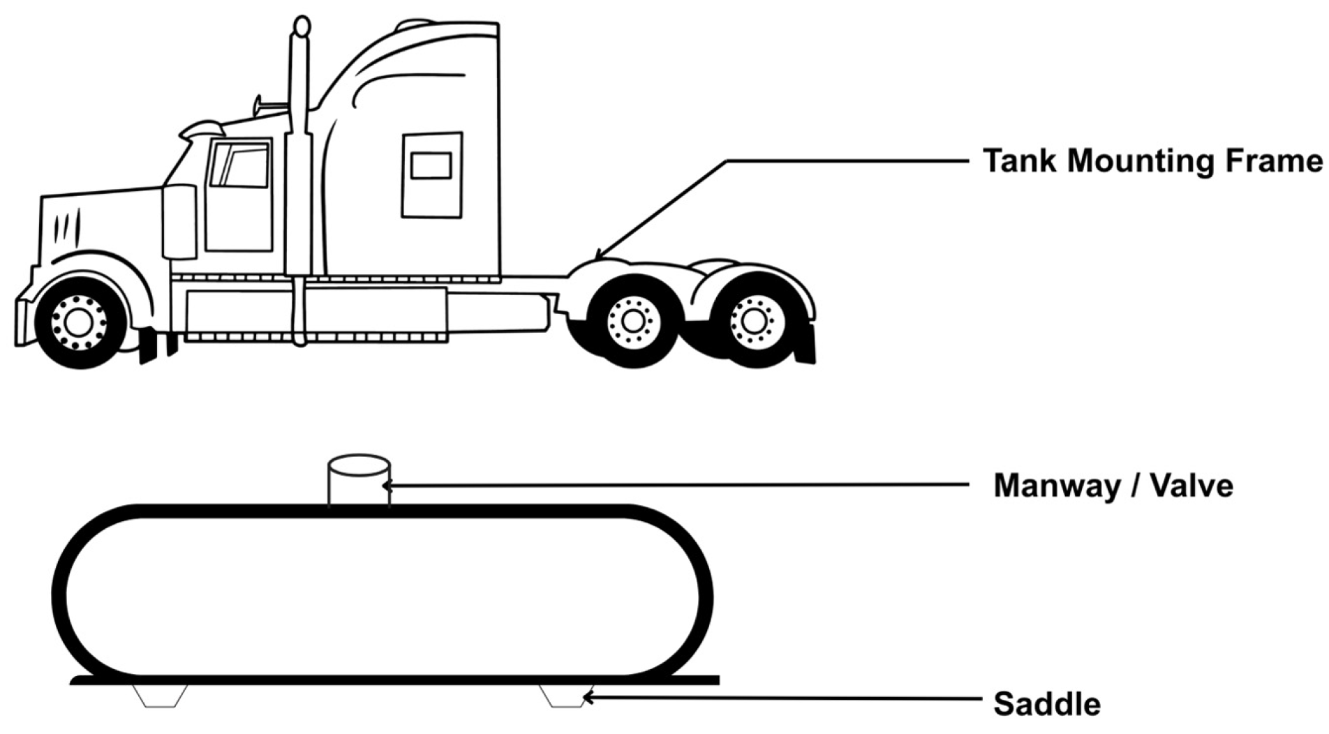
The overall aim and analysis in Sridhar and Kaisare’s study [10] centered on using a two-dimensional model to simulate the refilling of a hydrogen stainless-steel (SS) storage tank containing MOF-5 adsorbent under both room temperature and cryogenic conditions. This approach is considered novel in optimizing pipeline transport, one of the oldest and most widely used methods for gas distribution. However, several other logistical variables, discussed in this paper, are also known to affect the modeling of SS tanks in both transport and storage scenarios. Meeting the stringent industrial standards for stainless-steel fluid tank design can be particularly challenging. These include standards set by organizations such as EN and ISO, along with continuously evolving engineering requirements [12,13,14]. Many of these standards exist to ensure consistent safety during and after fabrication, especially in transport applications, such as when tanks are designed to be mounted on vehicles, as shown in Figure 2, a conceptual diagram that also serves as a simplified logistics and transport model: Figure 2 (top) shows a semi-truck with an empty chassis, highlighting the designated mounting frame for stainless-steel tanks, while Figure 2 (bottom) presents an empty cylindrical stainless-steel tank equipped with support saddles and a manway/valve for access. Together, these schematic figures model how tanks and vehicles are integrated, ensuring stability, accessibility, and compliance with transport safety standards.
On the other hand, these standards provide comprehensive guidelines for the design of atmospheric fluid storage systems, while also promoting uniformity in the selection of appropriate stainless-steel materials [2,10,15]. These materials can be evaluated based on their strength parameters and structural behavior under static pressure, both through manual testing and advanced simulations such as ANSYS 2024 R2 modeling [12,15]. Furthermore, the standards address not only material durability but also strict quality requirements to ensure safe operation during transport and storage, even in extreme conditions, such as cryogenic temperatures and hydrogen-rich environments [16].
These considerations are driving the development of critical logistics and transport models by many researchers, including Ansari et al. [17], Carkovs et al. [18], and Shammazov and Karyakina [19]. Reviewing these models while incorporating two laboratory-tested stainless-steel grades, 316 and 304L, is the central focus of this paper. In particular, the study aims to verify whether gases can be reliably stored or transported using specifically designed SS tanks [20]. Although several scholars, such as Emrani and Berrada [21] and Wang et al. [22], have attempted to address this question through modeling and experimental validation, this work expands on it by also investigating the effects of new heat treatment processes, specifically continuous annealing, on the elemental composition of stainless steel grades 316 and 304L used in tank design and fabrication. While numerous studies have examined either stainless-steel characterization [21] or logistics/transport models [3] in isolation, few have integrated these domains to show how material properties constrain logistics optimization. This study addresses that gap by combining experimental validation of 316/304L grades with logistics modeling frameworks, thereby linking micro-scale material behavior with macro-scale supply chain performance. Recent advances in smart logistics and digital-twin-based cryogenic systems [23,24] further motivate this integration.

2. Materials and Methods

2.1. Material Selection and Process

This study analyzes two stainless steel grades, 316 and 304L. Grade 316 was produced using a vacuum induction furnace at 1250 °C, held for 16 h, followed by open die forging. Grade 304L was also produced via vacuum induction melting but was processed at 1300 °C, followed by hot rolling at 1140 °C. These procedures were selected to provide a broad process overview regarding the chemical compositions of stainless-steel materials commonly used in structural tank design. Both grades then underwent an isothermal annealing at 700 °C for 1 h in a bench furnace, followed by air cooling. The purpose of this treatment was to examine the effects of transient temperature exposure on the chemical composition of the samples, particularly in light of the unclear oxidation mechanisms in Fe-Cr-Mn austenitic stainless steels with high chromium content following exposure to elevated temperatures and subsequent air cooling [22].
This investigation is motivated by the ongoing challenges in stainless-steel applications, which have led to increasingly complex compositions designed to yield new, high-performance components [25]. The elemental compositions were compared against two certified calibration blocks, as well as against compositions found in stainless steel tank materials discussed in this study. It is important to note that both 316 and 304L stainless steel grades are susceptible to sensitization, a condition that can lead to intergranular corrosion (IGC) and intergranular stress corrosion cracking (IGSCC) in corrosive environments. These vulnerabilities may cause premature failure of fabricated tanks during pre-commissioning or operational service periods [26,27]. Although further experimentation on intergranular corrosion conditions and mechanical properties is planned, such testing could not be completed within the timeframe of this study.
The bulk stainless-steel materials used consisted of one industrial hot-forged (316) and one hot-rolled (304L) sample, as shown in Figure 3.
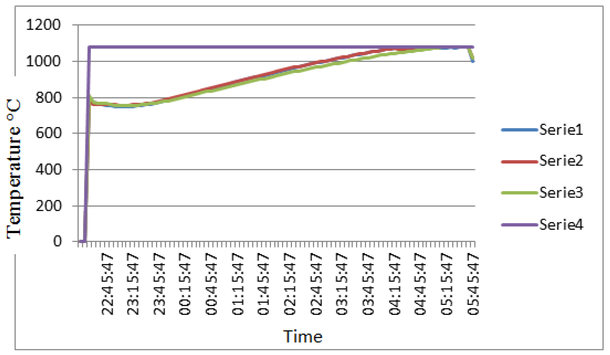
The respective diameters of the bulk materials were 369 mm for 316 and 50 mm for 304L. Both were initially fully annealed for 1.5 h at 1040 °C, as shown in Figure 4.
In Figure 4, the furnace initially maintained a minimum temperature of 750 °C before the materials were loaded. The target temperature was set to 1080 °C (Series 4), with the holding time programmed to begin automatically once the internal heating elements, Series 3, Series 2, and Series 1, reached 1040 °C. The total holding time was 1.5 h. The timer began at 04:05:47, and the materials were removed from the furnace at 05:35:47. This was immediately followed by water quenching in a water tank. The transfer time from the furnace to the water tank was less than 20 s.
Multiple specimens (20 mm × 20 mm) were extracted from the longitudinal direction of each bulk material at 0.5 radius and then subjected to metallographic preparation for analysis, as illustrated in Figure 5.
Before conducting elemental characterization of the samples using a scanning electron microscope (Zeiss Ultra 55 FEG-SEM, Oberkochen, Germany) equipped with energy-dispersive X-ray spectroscopy (EDX, Oxford Instruments INCA, Oxford, UK), two certified calibration blocks, coin-grade standards of AISI Type 304L (UNS S30403) and 316 (UNS S31600), were used to establish the expected chemical composition of the specimens. This initial analysis was performed using a Niton XL2 X-ray fluorescence (XRF) spectrometer (Thermo Fisher, Waltham, MA, USA), which is capable of detecting up to thirty elements, as shown in Figure 6a.
The reading duration using the Niton XL2 XRF analyzer was set to a minimum of 4 s per spot for each calibration coin. The results obtained from the certified calibration blocks are presented in Table 2.
As previously indicated, isothermal annealing at 700 °C for 1 h in a bench furnace is performed on the parent material samples, Figure 6b. The as-received 316 and 304L bulk stainless-steel samples were heat treated at a constant temperature of 700 °C and subsequently air-cooled, with the aim of modifying their metallurgical and mechanical properties. Although the mechanical property results are not included in this paper, they will be presented in a subsequent study. Prior to loading, the furnace was preheated, and the stainless-steel samples were inserted using a pair of tongs. After the heat treatment, the samples were also removed using tongs. Unlike the typical use of castable mounting resins, the test specimens (20 mm × 20 mm blocks) were mounted using screws on a sample holder fixed to a rotating disc and prepared according to ASTM standards [28] for further analysis. Both 316 and 304L samples were etched using an etchant composed of 50 mL ethyl alcohol and 50 mL hydrochloric acid (aqua regia). The sample labels and designations are provided in Table 3.

2.2. Methodology

The methodology employed in this study integrates both experimental analysis and a systematic literature review. The experimental analysis focuses on the chemical and elemental compositions of stainless-steel grades 316 and 304L, materials widely used in the design and fabrication of stainless-steel (SS) tanks. This dual approach not only provides experimental evidence but also situates the findings within the broader research landscape by identifying knowledge gaps, avoiding redundancy, and highlighting emerging areas. For the literature review, a systematic protocol was adopted to ensure rigor and transparency. Literature searches were conducted on Scopus, Web of Science, and Google Scholar, covering all publications available up to March 2025. Search terms were developed by listing alternative expressions and keywords related to logistics models, transport models, and stainless-steel tanks (Table 4).
Boolean operators such as “AND” and “OR” were applied to refine search strings (e.g., “logistics AND transport” or “stainless steel AND tank”). Studies were included if they were peer-reviewed, written in English, and directly relevant to logistics or transport models in stainless-steel tanks. Eligible works contained empirical data, theoretical frameworks, or case studies that aligned with the experimental focus of this research. Studies were excluded if they focused primarily on high-speed steel (HSS) in the context of cutting tool design, were non-English, inaccessible in full text, or otherwise outside the scope of stainless-steel fluid storage tanks.
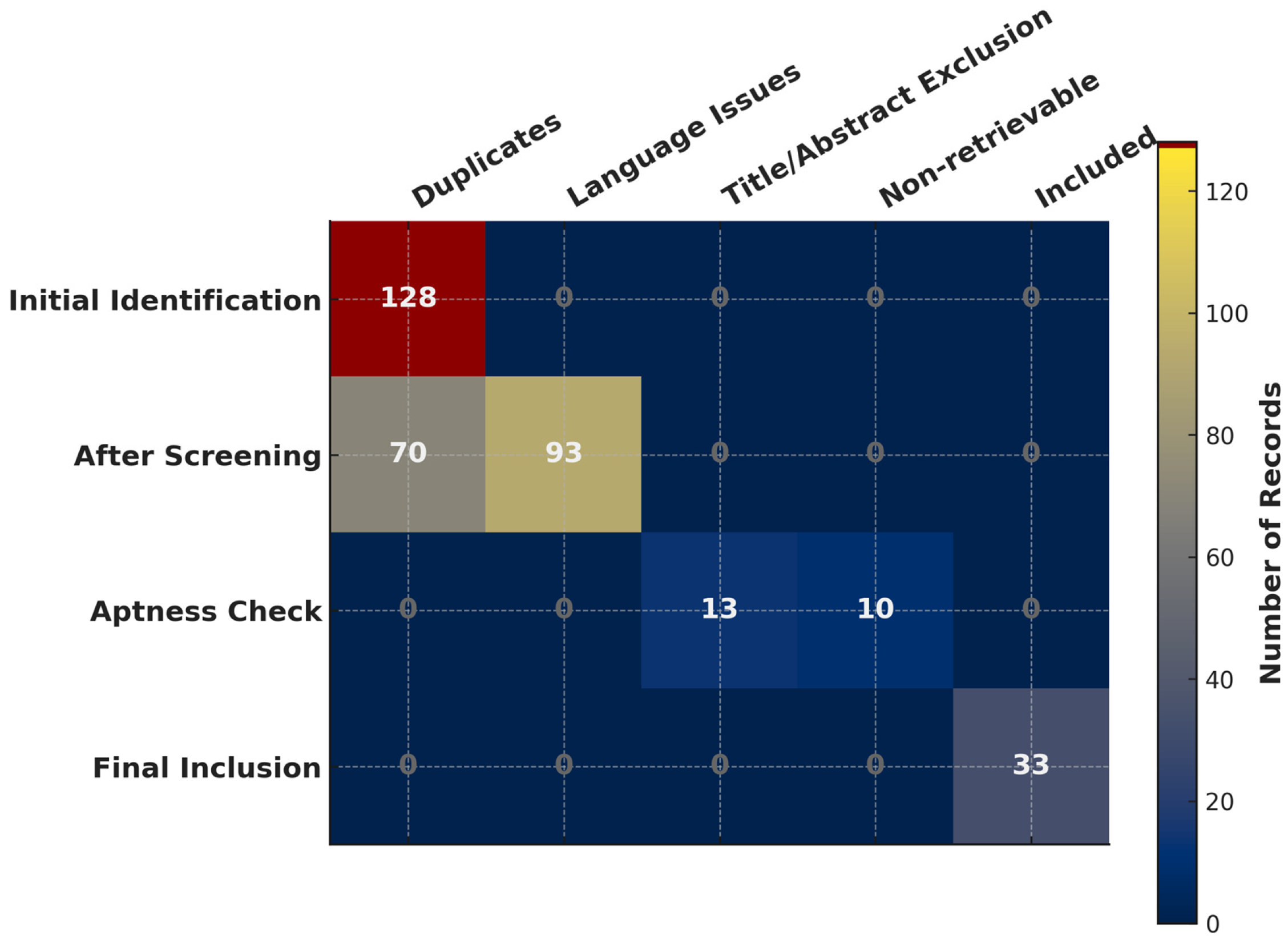
The search initially identified many unrelated articles. After identifying and removing 128 duplicates, the remaining records were screened. 23 articles were removed based on titles, abstracts, and non-retrievable. Ultimately, 33 peer-reviewed articles were retained for synthesis.
Within this final selection, two studies (Sridhar and Kaisare; Lisowski and Czyżycki) stood out prominently due to their methodological and applied significance. Sridhar and Kaisare [10] provided a critical analysis of transport models for the refueling of MOF-5-based hydrogen adsorption systems, offering a framework directly relevant to the optimization of gas transport efficiency in storage applications. Lisowski and Czyżycki [11], on the other hand, presented a detailed study on the transport and storage of LNG in container tanks, supplying empirical evidence that bridges theoretical modeling with real-world stainless-steel tank applications. These works were highlighted as they provided strong conceptual and applied foundations for the synthesis presented in this study. While foundational works such as those of Sridhar and Kaisare [10] and Lisowski and Czyżycki [11] provide critical baselines for structural and thermal modeling of stainless-steel tanks, more recent research extends these frameworks by embedding smart logistics, IoT monitoring, sustainability, and optimization-driven design.
Table 5 summarizes selected 2024 contributions that exemplify these advances and highlight their relevance for stainless-steel fluid storage tank logistics.
To minimize bias, the selected studies were critically compared against established frameworks such as the Finite Element Method (FEM) to validate their relevance and applicability. Conflicting findings were reconciled by prioritizing studies that evaluated thermal impacts through time-series designs, conducted numerical analyses of stainless-steel tanks, or examined fluid flow in stainless-steel storage systems. The experimental component complemented this review by analyzing the impact of heat (temperature) on the elemental compositions of stainless-steel grades 316 and 304L using energy-dispersive X-ray spectroscopy (EDS) mapping and comparing results with X-ray fluorescence (XRF) spectroscopy. Based on these combined approaches, the study addressed two key research questions:
(a)
What variables in the modeling of logistics and transport should be considered to optimize stainless-steel fluid storage tank design?
(b)
What effects does an isothermal annealing at 700 °C for 1 h in a bench furnace have on the elemental compositions of stainless-steel grades 316 and 304L?
To systematically structure and present the literature screening and synthesis process, we adopted an Evidence Gap Map (EGM) approach. EGMs provide a matrix-based visualization of where evidence exists and where gaps remain, rather than a flowchart of article selection. In this study, the rows represent stages of the review process (identification, screening, eligibility, inclusion), while the columns indicate reasons for exclusion or successful inclusion. The density of studies within each cell highlights concentrations of evidence and areas where research is lacking. The EGM diagram illustrating the inclusion and exclusion process during article selection is presented in Figure 7.
All schematic figures presented in this paper were developed by the author using Python’s Matplotlib library (version 3.11.4) and related vector-drawing tools. This approach was adopted because it ensures clarity, reproducibility, and complete control over the level of abstraction required for the study. Unlike detailed CAD models or factory blueprints, which often introduce unnecessary complexity, the Python-generated schematics are deliberately simplified to highlight only the essential design features relevant to the discussion. They are intended as conceptual visual aids that support the explanation of logistics, flow behavior, and thermodynamic considerations, rather than as detailed engineering drawings. For instance, Figure 2 provides original conceptual illustrations highlighting logistics and transport models of stainless-steel fluid storage tanks, including chassis mounting, tank support saddles, and flow control components. Likewise, Figure 1 illustrates a conceptual schematic of a stainless-steel vessel, showing a CIP spray ball, nitrogen vent, tangential return, and bottom drain, which emphasizes hygienic drainability, cleaning efficiency, and thermal control. By using custom-built schematics, the study maintains consistency across figures, avoids reliance on proprietary sources, and enhances the ability to tailor the illustrations to the research objectives.

Integration of Framework

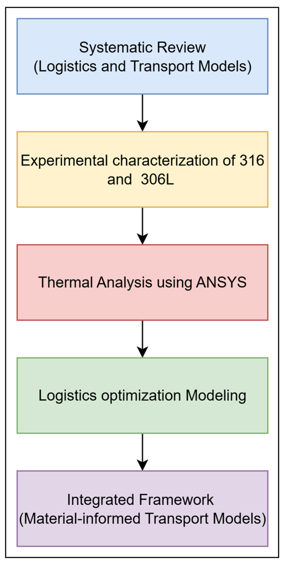
To unify the review, experimental, and modeling strands, a workflow schematic was developed, as shown in Figure 8. This diagram illustrates how the three methodological components converge: (i) the systematic review defines the scope of logistics models, (ii) experimental results supply validated material inputs, and (iii) simulations link these properties to logistics optimization. Together, this integrated workflow ensures that logistics frameworks are not abstract but grounded in stainless steel’s engineering realities.

2.3. Statistical and Uncertainty Analysis

All replicated EDS and XRF measurements were subjected to descriptive statistical treatment. For each element, mean values, standard deviations, and 95% confidence intervals (based on Student’s t-distribution for small sample sizes) were calculated. Group-level contrasts between specimen sets (A vs. B) were quantified using Hedges’ g to assess the magnitude of observed differences [31]. Outliers that exceeded instrument resolution or suggested spectral overlap (e.g., anomalous carbon and europium readings) were excluded from inference and are discussed transparently in the Limitations section.
For modeling work, uncertainty in material parameters, such as elastic modulus, thermal expansion coefficient, and yield strength, was propagated into both finite element and logistics simulations. Local sensitivity analysis was applied to identify dominant contributors to output variability, while Monte Carlo sampling was used to generate distributions of predicted quantities (e.g., maximum von Mises stress, insulation heat ingress, refueling costs). Model outputs are reported with mean values and 95% confidence intervals to ensure comparability with experimental uncertainty estimates.

Acquisition Parameters (EDS)

Accelerating voltage: 15 kV (primary) with confirmatory low-kV checks at 5 kV for light-element artefacts.
  • Beam current: ∼1 nA (Faraday-cup referenced).
  • Working distance/take-off angle: ~10 mm/~35°.
  • Live time per spectrum: 60–100 s; 3–5 repeat spectra per spot; 3 spots per sample.
  • Detector: silicon drift detector (SDD); energy resolution ~125–135 eV at Mn Kα.
For quantification and deconvolution, spectra were background-corrected (model-based) and quantified with ZAF/(ρz) corrections. Line overlaps (e.g., Cr Kβ/Mn Kα, Mo L lines near light-element region) were resolved using the software’s peak deconvolution; fits were checked manually against residuals. Calibration was verified daily with a multielement reference standard.
For reporting, detection limits, and uncertainty, elemental results are now reported in wt.% and at%. Typical EDS detection limits in this configuration were ~0.1–0.3 wt.% for mid-Z (atomic number) elements and ~0.5–1.0 wt.% for light elements (e.g., C). Expanded uncertainty (≈95%) combines repeatability, calibration, and counting statistics, yielding ±0.2–0.3 wt.% for major constituents (Cr, Ni) and ±0.5–1.0 wt.% for minor/light elements (Mn, Mo, Cu, C). Values below LOD are flagged as “< LOD” rather than zero.
For quality checks & outlier handling, to test whether high carbon arose from measurement artefacts, we (i) re-acquired spectra at 5 kV, (ii) repeated measurements on fresh, unpainted mounting areas, and (iii) inspected time-series spectra for contamination growth. The isolated C = 7.1 wt.% and high Mn instances were not reproducible under these controls and are attributed to surface contamination and/or peak-fit cross-talk; they are excluded from quantitative tables and discussed in the Limitations Section. Full parameter sets and replicate statistics (mean ± SD; 95% CI) are provided in the tables in the Results Section.

3. Computational Analysis and Validation

3.1. Variables in Logistics of Transport Modeling

In engineering, it is well established that cases typically possess one or more attributes or characteristics, commonly referred to as variables. These variables represent measurable properties that can take on different values across different cases [11]. This principle is evident in the works of Sridhar and Kaisare [10] and Lisowski and Czyżycki [11], where the structural attributes of tanks are a focal point. Sridhar and Kaisare [10] designed two tank systems: the end-flow system and the flow-through system. Although they differ in design, both systems share similarities, particularly in their structural and functional aspects. This dual-tank approach is also reflected in Lisowski and Czyżycki [11], highlighting the importance of comparing analogous cases. More recent studies, such as those by An et al. [23] on digital twin-based cryogenic logistics and Srinivasan et al. [24] on optimization of LNG tank transport, extend this principle by embedding these variables into computational models for predictive simulations.
In the study by Sridhar and Kaisare [10], hydrogen gas is introduced into a fixed bed, where it is either adsorbed or stored in interparticle pores. In contrast, the flow-through system allows for continuous hydrogen flow, with a dedicated inlet and outlet. While one may debate the specific modeling assumptions, it is evident that the authors considered key variables in the tank design, such as size calculations, material selection (see Table 1), and customization based on compatibility. Similarly, Al-Mohannadi et al. [29] emphasize the role of materials engineering and thermal stability in LNG tank logistics, underscoring that variable selection must include both structural and thermal performance criteria.
A similar emphasis on structural detailing is observed in Lisowski and Czyżycki [11], where the tank design is meticulously sectioned and labeled as follows:
  • Inner container;
  • Inner supports (synthetic materials);
  • Outer container;
  • Insulation;
  • Radiation shields;
  • Vacuum;
  • Outer supports;
  • Container frame;
  • Accessories.
The detailed structural components serve to illustrate the complexity and variability of stainless-steel tank systems in both experimental and applied research contexts. Newer frameworks, such as those introduced by Fariña et al. [30], incorporate sustainability-oriented logistics variables—carbon footprint, insulation efficiency, and lifecycle cost—into transport modeling, thereby expanding the scope of variables beyond traditional structural and thermal considerations.
In other words, what variables should be considered in modeling the logistics of transport to ensure optimization in stainless-steel (SS) fluid storage tanks? Similar to the approach of Sridhar and Kaisare [10], the work of Lisowski and Czyżycki [11] also emphasizes key variables in tank modeling. Specifically, they focus on:
(a)
The structural configuration of the designed stainless-steel vessel;
(b)
Thermal performance calculations of mobile tanks intended for the transport and storage of liquefied natural gas (LNG).
Lisowski and Czyżycki [11] introduced novel cryogenic tank designs, including both mobile and stationary vessels. Their mobile cryogenic container is engineered for the transport of LNG and other liquefied gases under extreme conditions, capable of withstanding temperatures as low as –196 °C (variable c). Additionally, two logistics solutions are outlined: a container that can be fully transported and detached from the vehicle, allowing it to remain on-site at the workplace, and a reloading solution where LNG is transferred from a mobile tank to a simplified container or fixed tank at the workplace.
These solutions also address the facility location problem (variable d), which is concerned with determining the optimal spatial configuration of a facility network to maximize service levels while minimizing cost [17]. This problem, highlighted in Lisowski and Czyżycki [11], is a critical component in transport logistics modeling. Although the simplified container and mobile tanks designed by Lisowski and Czyżycki [11] were not physically tested in transportation scenarios, their designs demonstrate professional engineering rigor. The tanks are built to meet stringent safety standards, particularly in their ability to tolerate cryogenic temperatures such as –196 °C. As with Sridhar and Kaisare [10], it is assumed that essential variables, including material selection, were carefully considered in the design process.
As previously noted, Ansari et al. [17] argue that facility location is one of the most crucial variables in transport logistics modeling. They emphasize that the core issues in such models often involve multiple cost components, including transportation costs, fixed facility opening costs, and variable operating costs. In discrete modeling settings, the underlying network consists of demand points and potential facility locations [11,17]. Furthermore, Ansari et al. [17] classify these as incapacitated facility location problems, which can be analyzed using both one-dimensional and two-dimensional models.
All logistics modeling challenges presented in their work are addressed through the Continuous Approximation (CA) method, which is recognized as an efficient and effective approach for modeling complex logistics problems.

3.2. Modeling for Logistics of Transport

Various modeling techniques have been proposed and implemented in this study to address logistics and transport problems associated with stainless-steel (SS) storage tanks. One such approach is the CA modeling technique, which is particularly applicable to the facility location proposals presented in Lisowski and Czyżycki [11]. This modeling approach can be classified as a one-dimensional Uncapacitated Facility Location (UFL) problem, an area that has been extensively reviewed and recommended by many researchers, including Ansari et al. [17].
Ansari et al. [17] assert that the straightforward structure of the one-dimensional UFL model is effective in illustrating the underlying principles of location-based continuous approximation. This model is relevant for practical infrastructure system design challenges, such as the planning of distribution centers, a category into which Lisowski and Czyżycki’s [11] proposal fits. According to Ansari et al. [17], the problem is defined as follows [17]:
  • Let t ϵ T≔ [ t 0 , T] represent the location range.
  • Let d(t) denote the product demand density at each location t and let D(t) represent the cumulative demand from t0 to t.
  • Facilities are built at locations t = f(t), … t N , each associated with opening cost f(t).
  • Once facilities are in place, each demand point is served by its closest facility.
  • The transportation cost to serve each unit demand at the location t is modeled as the product of the distance to its nearest facility and a constant scalar c, i.e.,
Costt  = c . t t i where t i is the closest point to t.
The total transportation cost is represented graphically as the shaded area [17]. For notational convenience, Ansari et al. define midpoint boundaries for each facility region as: t i   t i + t i + 1 2 , i = 1 , , N 1 ,   t 0   = t 0 and t N   = T.
The objective of the model is to determine the optimal facility locations t 1 , , t N that minimize total cost, which includes both the fixed facility opening costs and the transportation costs to serve demand across the network. This modeling approach provides a flexible and insightful method for tackling real-world logistics problems and is particularly relevant when optimizing the layout and operation of stainless-steel fluid storage tank systems in distributed supply networks as follows [17]:
t 1 t 2 t N ϵ T m i n i = 1 N   f t i + c t i 1 t t i t t i d t d t  
The influence area of facility i (i.e., the area that facility i serves) is defined as: Ti [ t i   1 ,   t i   ), and its size given by: As ( t ) = t i + 1 t i   , i   = 1,… N. Accordingly, the total cost (previously expressed as Equation (3)) can be modified as [17]:
t 1 t 2 t N ϵ T m i n i = 1 N   T i   f ( t i ) A s ( t ) + c A s t 4 d ( t i   ) d t ,  
where   t i   ϵ   T i satisfies the condition that 1 4 [ t i   t i 1 ] 2  d ( t i   ) represents the shaded area under the curve over the interval Ti. Ansari et al. [17] assume that functions d(t) (demand density) and f(t) (facility opening cost) vary slowly over the domain T. Therefore, without significant loss of accuracy:
  • Demand d ( t i   ) can be approximated by d(t).
  • The discrete area function As( t ) can be replaced by a continuous service area function A(t). This leads to the continuous approximation (CA) of Equation (4) as:
{ A ( t ) } t ϵ T m i n T   f ( t ) A ( t ) + c A ( t ) 4 d ( t ) d t .
To extend the CA scheme to two-dimensional space Ansari et al. [17] formulate the total cost function as:
A t t ϵ T m i n T   f t A t + c m c A t d t d t ,
Here, the Scalar cm represents the average transportation distance coefficient within the service zone. This coefficient depends on the distance metric and the assumed geometry of the influence areas, as reviewed extensively in the literature [17].
Using a Euclidean distance metric, the value of cm is:
  • 0.376 for circular areas;
  • 0.377 for hexagonal;
  • 0.382 for square;
  • 0.403 for triangular zones.
This suggests that the effect of influence area geometry on total cost is relatively minor, provided the area does not become overly elongated, which aligns with the geometry of service areas in the tank designs discussed by Lisowski and Czyżycki [11].
Nevertheless, in real-time scenarios, any transport logistics model typically operates under random demand and within a stochastic environment [18]. Additionally, the timing of product refilling, for instance, is also a random variable. This implies that, for a quantitative analysis of product replenishment, one must account not only for the stock levels predicted by deterministic dynamic systems but also for the possible random deviations from those idealized projections [18]. To address this, Carkovs et al. [18] proposed a deterministic model that assumes random product demand occurring at random time intervals. However, in the context of Sridhar & Kaisare [10] and Lisowski & Czyżycki [11], such a deterministic model approach is insufficient. Instead, a stochastic model is more appropriate. This is because the demand for the designed stainless-steel (SS) tanks, assuming they are to be manufactured and sold, is inherently uncertain and cannot be predicted with precision. In such cases, demand must be modeled using probability distributions, such as normal, Poisson, or uniform distributions [17]. As previously noted in the introduction, both Sridhar & Kaisare [10] and Lisowski & Czyżycki [11] emphasize the complexity and specialized logistics solutions required for gas transportation. These solutions require advanced transportation models that can accommodate such uncertainties.
On one hand, Lisowski & Czyżycki [11] modeled the SS mobile tank for the transport and storage of liquefied natural gas (LNG) with a focus on thermal calculations, ensuring the gas can be stored for extended periods. However, residual gas in the interstitial space between the tank walls can still conduct heat. The extent of this heat conduction depends on several factors, including heat exchange under cryogenic conditions and calculations involving thermal insulation and structural supports, using finite element method (FEM) modeling.
Furthermore, since heat conduction due to radiation and residual gas may interact reciprocally under cryogenic conditions, Lisowski & Czyżycki [11] argue that this interaction cannot be neglected. In other words, this constitutes a random deviation from the idealized behavior, which must be quantitatively estimated [10,11,18]. To model the residual gas conduction, the first step is the application of the Knudsen number (Kn). When Kn ≈ 1, the residual gas can no longer be modeled as a continuous medium [11]. Instead, the Corruccini formula, which has been extensively validated and reviewed in the literature, is used as the preferred approach [11]:
q g r   =   Y + 1 Y 1 a R 8 π M T p 1 2 P T 2 T 1 ,  
Y = c p / c V
a = a 1 a 2 a 2 a 1 ( 1 a 2 ) A 1 / A 2 ,  
where
  • c p represents the specific heat of air at constant pressure [J/(kg K)];
  • c V represents the specific heat of air at constant pressure volume [J/(kg K)];
  • α 1 , α 2 represent heat transfer coefficients for the surface of the inner tank and the outer tank;
  • A1, A2 represent an area of inner tank walls and outer tank walls [m2];
  • R represents the gas constant [J/(mol K)];
  • M represents the molar mass of the residual gas [kg/mol];
  • T p represents temperature in the pressure measurement point (on the outer tank) [K];
  • P represents the pressure of the residual gas [Pa];
  • T2, T1 represent the temperature of outer wall of inner tank and outer shield of inner tank insulation [K].
On the other hand, heat insulation modeling was conducted to estimate the usability of insulation materials in the construction of LNG tank containers [11]. This represents yet another random deviation from an idealized variable that must be accounted for [10,11,18]. Several types of insulation materials were selected for the simulation-based study, which involved determining the average heat fluxes to the LNG under various random environmental conditions [11,18]. The insulation materials analyzed by Lisowski and Czyżycki [11] were primarily based on aerogel, a substance widely reviewed and recommended by numerous scholars due to its exceptional thermal performance. To evaluate their effectiveness, finite element method (FEM) calculations were performed using the SolidWorks (2024 Student version) Simulation program. The results of the analysis include temperature distribution and heat flux within one of the tanks (Type 1) [11].
Nevertheless, heat leakage was also calculated using a formula previously outlined by several scholars [11]:
L =   86400 · Q c · A h · F ,  
where
  • Qc represents average heat flux on the outer surface of the tank [W/m2];
  • A represents an area of the outer surface of the tank [m2];
  • h represents the latent heat of vaporization [J/ k g ];
  • F represents the total mass of LNG in the tank [ k g ].
The overall simulation results demonstrated extended storage durations for the simplified stainless-steel (SS) containers, comparable to those of the stationary SS tanks. As a result, stationary tanks are found to be easier to transport when empty [11]. These two findings align with and help fulfill the primary objectives of this study.
In contrast, three isotherm models, namely, Unilan, Tóth, and modified Dubinin–Astakhov (DA), were used by Sridhar and Kaisare [10] to fit the experimental data for hydrogen adsorption, focusing on their impact on the transport (refueling) behavior of the adsorbent bed. For both the flow-through and end-flow batching systems, the choice of isotherm model had the most significant influence on predicting refueling performance [10].
While Figure 9a,b illustrate the CAD model of the LNG storage tank and its cross-section, Figure 9c,d illustrate the mesh model and boundary conditions of the LNG storage tank during steady-state thermal analysis. Notwithstanding, the heat of adsorption for the three isotherm models is presented in Figure 10. For the Unilan model, the Clausius–Clapeyron relation, as previously studied and reviewed by other scholars, is applied. This relationship is expressed as follows [10]:
H = E m a x   1 x s 1 exp 1 x s R T x s 1 exp x s R T
where
  • x = n / n m a x and
  • s =   E m a x E m i n .
For the Dubinin–Astakhov isotherm model, which is widely used for microporous materials and has been previously studied and reviewed by other scholars, the equation is given as follows [10]:
n a = n m a x e x p R T α + β T l n p o p m
where
  • α represents the enthalpic factor;
  • β represents the entropic factor;
  • po represents the saturation pressure of the bulk gas;
  • p represents the operating pressure.
Figure 9. (a) CAD model of the LNG storage tank, (b) cross-section of the tank, (c) uniform mesh of the tank, and (d) Steady-State Thermal setup with boundary conditions for the LNG tank.
Eng 06 00275 g009
Figure 10. Steady-state thermal analysis of LNG storage tank.
Eng 06 00275 g010
And for the Tóth, which is an empirical model possibly developed from the theory of heterogeneous adsorption, modeling low- to high-pressure adsorption involves a quasi-Gaussian energy distribution at the adsorption site [10]. According to Sridhar and Kaisare [10], the definite volume of hydrogen adsorbed for the model is expressed as follows:
n a = n m a x b 0 exp q T T p 1 + b 0 exp q T T p n 1 n
where
  • p represents the equilibrium pressure (Pa) and the heterogeneous parameter.
  • n represents n0 + αT, depending on temperature.
  • b 0 ,   q T ,   α ,   n 0 are parameters that are factored into the experimental data of the hydrogen adsorption on the cubic metal–organic framework compound (MOF-5). In conclusion, Sridhar, and Kaisare [10] believe that making a proper choice among the adsorption isotherm models is important. The effect of temperature on the physical properties of gas, adsorbent, and walls is also crucial for consideration.

3.3. Finite Element Modeling

The FEM of the stainless-steel fluid storage tank was constructed in ANSYS using 10-node quadratic tetrahedral solid elements (SOLID187). The baseline mesh consisted of ~145,000 elements and ~185,000 nodes, with a minimum element quality of 0.72 (Jacobian ratio), exceeding the accepted threshold of 0.6 for stability in cryogenic tank modeling [12]. Mesh refinement studies were carried out at ~95 k, ~145 k, and ~220 k elements. Convergence was confirmed as maximum von Mises stresses differed by only 2.3% between the medium and fine meshes, while predicted maximum heat flux varied by <1.8%. Based on this, the medium mesh (~145 k elements) was adopted for subsequent simulations as a balance between accuracy and computational efficiency [15].
Solver tolerances were set to 1 × 10⁻⁶ for thermal residuals and 1 × 10⁻⁴ for displacement residuals, consistent with accepted finite element practices in LNG tank modeling [22]. Model predictions of conductive heat ingress (37.7 W/m2) were benchmarked against a 1-D Fourier conduction solution, showing a deviation of 3.9%. In addition, model outputs for boil-off trends and localized stresses were qualitatively consistent with published LNG tank analyses [3,4,22]. These steps confirm that the simulation is mesh-independent, solver-converged, and validated against both analytical benchmarks and literature data.
The process begins with the construction of the tank geometry, followed by meshing with quadratic tetrahedral elements. Mesh refinement and convergence checks were conducted to ensure accuracy, after which solver tolerances were applied for both thermal and structural simulations. The final stage involved validation of model outputs against analytical conduction theory and published LNG tank benchmarks [3,4,12,15,22]. This workflow ensures numerical transparency and provides a robust framework for linking stainless-steel properties to logistics-oriented transport models.

Case Study with an Example of the LNG Storage Tank in Logistics

The LNG tank is designed with a total storage capacity of 50,000 m3 and features a robust, multilayered construction optimized for thermal insulation and structural stability, as shown in Table 6.
The tank has an overall length of 70 m, with an inner diameter of 25 m and an outer diameter of 28 m, providing ample space for insulation layers and vacuum gaps. Both the inner and outer tank walls are constructed with a uniform thickness of 40 mm, ensuring consistent structural integrity. Positioned between these walls is a 1.25 m thick aerogel insulation layer, renowned for its extremely low thermal conductivity, which provides excellent resistance to heat ingress. Additionally, a 160 mm vacuum gap separates the aerogel layer from the outer wall, further enhancing insulation by minimizing both convective and conductive heat transfer. This advanced tank design ensures the safe and efficient storage of cryogenic LNG under extreme temperature differentials.
Figure 10 presents the results of a steady-state thermal analysis conducted on the LNG storage tank to evaluate the distribution of total heat flux across the tank’s structure.
The analysis was performed at 5 s into the simulation, revealing a maximum heat flux of 37.724 W/m2 and a minimum approaching zero (9.0119 × 10⁻¹⁴ W/m2), indicating excellent thermal insulation performance. As illustrated in the color map and vector field, the highest heat flux occurs at the supporting rings and interface zones, which act as thermal bridges, allowing for greater heat penetration. In contrast, the aerogel insulation and vacuum gap substantially reduce heat transfer across most of the tank’s surface, as evidenced by the predominance of low heat flux regions (blue and green zones). The direction and magnitude of heat flow are visualized through vector arrows, clearly depicting heat ingress from the external environment toward the inner tank. These results confirm the effectiveness of the thermal design in minimizing heat gain and maintaining the cryogenic conditions required for liquefied natural gas (LNG) storage.
The maximum heat flux value (37.724 W/m2) is consistent with established ranges reported in the literature, such as the cryogenic LNG transport studies of Lisowski and Czyżycki [11], where comparable thermal losses were modeled, and the benchmarks outlined by Boiler et al. [32], who highlighted the influence of insulation architecture and structural discontinuities on boil-off rates. The alignment of our results with these prior studies provides confidence that the simulation approach is valid and anchored in recognized thermal behavior of stainless-steel storage systems.
As recent studies emphasize, temperature-dependent material and insulation properties are critical to accurate tank modeling [2,3,16]. Table 7 summarizes the key thermophysical values of stainless steels 304L/316, aerogel insulation, and support materials, which were adopted for the present analysis.
Values for stainless steels are taken from the ASME Boiler and Pressure Vessel Code [32]. Tank-level thermal performance trends are supported by Wang et al. [2,3], and toughness degradation is consistent with hydrogen embrittlement data in 316 stainless steel [16]. Aerogel values are representative and consistent with recent thermophysical studies on advanced aerogels [9].

3.4. Continuous Approximation (UFL)—Numerical Example and Sensitivity

We model an LNG/H2 distribution corridor of length L = 200 km with uniform demand density λ (kg day−1 km−1). Let C t be the per-kg-km transport cost (fuel, labor, vehicle), and F the daily fixed cost per facility (CAPEX amortization + OPEX). If facilities are evenly spaced with spacing s, the number of facilities is n = L/s. For a line corridor, the average haul distance to the nearest facility is s/4, so the daily transport cost is [17]:
C h a u l =   C t ( λ L ) ( s / 4 )
The facility cost is C f a c = (L/s) F. Total daily cost is:
C ( s )   = ( L / s )   F + C t λ L ( s / 4 )
Minimizing C(s) yields the classical CA spacing:
s *   =   ( 4 F / ( C t λ ) ) ,   s *   = L / s * .
For the Baseline instantiation (LNG/H2 corridor), we adopt representative values consistent with mid-scale LNG/H2 distribution (logistics planning) [10,24]:
  • Corridor length L  = 200 km.
  • Demand density λ = 500 kg day−1 km−1 (total 100,000 kg day−1).
  • Transport cost cₜ  =   0.02 USD (kg·km)−1.
  • Facility fixed cost F  = 2000 USD day−1.
For Optimal spacing and cost: s* = ( ( 4 × 2000 ) / ( 0.02 × 500 ) ) = ( 800 ) ≈ 28.3 km, n* = 200/28.3 ≈ 7.
  • Facility cost ≈ 14,000 USD/day.
  • Transport cost ≈ 14,142 USD/day.
  • Total ≈ 28,142 USD/day.
For the one-factor sensitivity (±25%), we vary one parameter at a time around the baseline to illustrate how spacing and cost shift, as shown in Table 8.
Following stochastic extensions in transport logistics [18], we varied facility cost, transport cost, and demand density by ±25%. The optimal spacing follows s* F / ( C t λ )   . Higher facility cost widens spacing (fewer sites), while higher transport cost or higher demand density tightens spacing (more sites). This convex trade-off between facility and haul cost aligns with LNG supply chain challenges recently highlighted by Srinivasan et al. [24].
As noted in hydrogen transport models [10], corridor-level spacing directly constrains tank sizing and refill cadence. More frequent refills (due to higher demand or haul costs) place stricter requirements on insulation performance, pressure rise limits, and load cycling in stainless-steel LNG/H2 tanks.

4. Experimental Results and Analysis

4.1. Elemental Compositions of Stainless Steels (EDS Mapping)

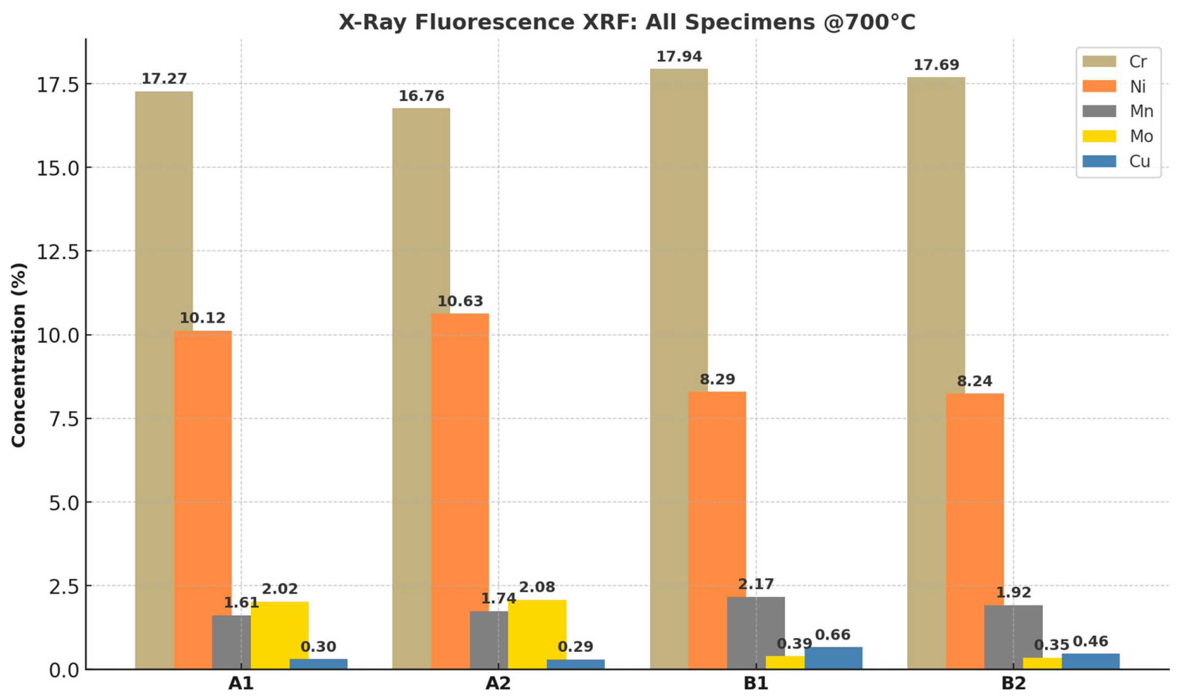
Figure 11 shows the EDS-mapped compositions of samples A1, A2, B1, and B2, representing water-quenched and air-cooled states. All samples retained high chromium and nickel contents, consistent with their roles in corrosion resistance and formability. Sample A1 displayed a significantly higher molybdenum content (≈2.5 wt.%), in line with the UNS S31600 standard. Spectrum 3 detected silicon at 0.6 wt.%, within the expected ≤1.0 wt.% range. However, Figure 11b revealed an anomalously high carbon reading (7.1 wt.%), and Figure 11b,c showed manganese contents of 2.5 wt.%, slightly exceeding the ≤2.0 wt.% limit.
The elevated molybdenum content in sample A1 confirms grade-specific alloying typical of 316 SS and its resistance to hydrogen embrittlement, consistent with prior literature. The anomalous carbon and manganese values are attributed to EDS resolution limitations (≈ approximately 130 eV), resulting in signal overlap and inaccurate quantification. EDS mapping confirms that the studied SS grades maintain expected alloying compositions critical for corrosion resistance and mechanical reliability. However, care must be taken in interpreting anomalous EDS values due to their limited resolution.

4.2. Elemental Compositions of Stainless Steels (X-Ray Fluorescence)

Figure 12 and Figure 13 display XRF-derived elemental weight percentages for samples A1–B2. Chromium levels were consistent across samples: 17.27% (A1), 16.76% (A2), 17.94% (B1), and 17.69% (B2). These values align closely with expected ranges for 316 (16–18 wt.%) and 304L (18–20 wt.%). All elements fell within reference limits except copper, which was detected in all samples. B1 exhibited the highest Cu content (0.669 wt.%), exceeding the ≤0.3 wt.% limit.
The consistency of chromium contents confirms alloy integrity under thermal treatments. The observed copper excess, although exceeding the specification, remains acceptable within the ±2σ confidence interval, reflecting natural variability and sample-size effects in XRF quantification. XRF analysis validates that the SS grades largely meet expected elemental specifications, with minor copper enrichment considered statistically permissible. Increasing the sample size would further reduce the standard error and improve confidence in the population means.

4.3. XRF Statistical Analysis

XRF statistical analysis was employed to evaluate the elemental composition and homogeneity of 304L and 316 stainless steels, enabling quantitative comparison of alloying element distributions and their influence on material consistency and performance. Table 9 summarizes elemental composition across all specimens, highlighting central tendencies and variability, while Table 10 compares groups A and B to assess compositional differences using Hedges’g effect size.
The observed compositional differences between specimen groups have direct implications for stainless-steel tank performance in fluid storage and logistics contexts. The lower Ni and Mo levels detected in Group B are significant, as both elements enhance corrosion resistance and cryogenic toughness [32,33]; their reduction may limit long-term durability under LNG or hydrogen service. Conversely, higher Mn and Cu contents can improve strength and deoxidation [11], but also increase susceptibility to localized corrosion in chloride-rich environments [32]. The slightly elevated Cr values in Group B remain within specification and continue to provide support for development. Collectively, these findings highlight that small but statistically significant variations in alloy chemistry can alter key input parameters for finite element and logistics models, influencing predictions of tank integrity, insulation performance, and lifecycle maintenance requirements [10,11,23]. This underscores the necessity of integrating compositional verification into logistics planning and model validation for stainless-steel tanks operating in demanding cryogenic supply chains [24,29,30].
The verified elemental compositions of stainless steels 316 and 304L after 700 °C annealing are summarized in Table 11.
Results are presented in both wt.% and at%, with uncertainties reported as ±SD and 95% confidence intervals. Values below the detection limit are marked as <LOD. As expected, Cr and Ni form the primary alloying elements, with Mo enriched in 316 relative to 304L. Conversely, 304L exhibits slightly higher Mn and Cu. These systematic differences are statistically meaningful, as confirmed by effect size calculations (Hedges’ g), and have implications for corrosion resistance and cryogenic performance.

4.4. Europium Detection in 304L (EDS Mapping)

Figure 14 shows that Europium (Eu) was unexpectedly detected in sample B1 (304L water-quenched) at 3.1 ± 0.8 wt.%.
The presence of Europium is significant because rare-earth elements are known to modify the elastic modulus and potentially influence the toughness of austenitic stainless steels. Its detection warrants additional mechanical testing.
The discovery of Europium suggests novel alloying or contamination pathways that may alter mechanical performance. Future work should include tensile and impact testing at room temperature and cryogenic conditions to assess the structural reliability of 316 and 304L in demanding applications.

5. Discussion

5.1. Technical Interaction of Stainless-Steel Properties with Logistics Modeling

A key dimension of stainless-steel fluid storage tank logistics lies in the interplay between material properties and transport models. The mechanical strength, density, and elastic modulus of stainless-steel grades 316 and 304L directly influence payload optimization and structural stability, requiring logistics models to account for weight distribution, stress tolerance, and deformation under dynamic loads [10,11]. Thermal properties, such as thermal conductivity, thermal expansion coefficient, and specific heat capacity, are particularly critical in cryogenic applications, where heat ingress has a significant impact on boil-off rates and overall energy efficiency [32].
Furthermore, the corrosion resistance of stainless steel reduces lifecycle maintenance costs, which must be incorporated into reliability-based and cost-optimization models [11,24]. Risk-oriented transport frameworks rely on an accurate representation of these material behaviors, particularly in long-distance LNG transport, where corrosion, fatigue, or thermal cycling can compromise structural safety [23,29]. By embedding these physical parameters into finite element or computational fluid dynamics simulations, logistics models can more accurately reflect operational realities, linking tank performance to transport outcomes [10,30].
This material–model integration ensures that logistics frameworks are not applied in abstraction but are instead grounded in the engineering characteristics of stainless steel, thereby strengthening the relevance of transport models to the domain of fluid storage tank design and operation.

5.2. Limitations

This study has several limitations that must be acknowledged. First, although EDS and XRF analyses confirmed the expected high Cr/Ni backbone and Mo content in 316 and 304L stainless steels, anomalous readings were detected in a few cases. The unusually high carbon value (7.1 wt.%) and isolated europium detection (3.1 wt.%) in one 304L sample) are considered unreliable artifacts of instrument resolution, spectral overlap, or contamination. To avoid misinterpretation, these values have been excluded from the main analysis and are discussed only as methodological outliers. Future work with higher-resolution techniques such as wavelength-dispersive spectroscopy (WDS), electron probe microanalysis (EPMA), or longer-dwell XRF is recommended to refine trace-element certainty.
Second, the FEM presented here is intentionally simplified to illustrate how experimentally derived properties of stainless steel (elastic modulus, thermal conductivity, expansion coefficients) can be integrated into logistics-relevant structural models. While benchmarking against literature has been incorporated in the revised version, more advanced validation against experimental deformation or cryogenic cycling data will be needed to strengthen predictive confidence.
Third, the CA modeling discussion remains preliminary. Although we introduced a simplified case study to demonstrate the method’s applicability to LNG logistics, further development is necessary to couple CA outputs with probabilistic refueling schedules, demand fluctuations, and facility-siting decisions.
Finally, while this study integrates literature review, material characterization, and modeling into a unified framework, it does not aim to deliver exhaustive coverage of all logistics models. Instead, the intention is to demonstrate how materials science constraints can and should be coupled with transport optimization frameworks. These limitations point toward future research directions where more advanced metrology, rigorous validation, and large-scale logistics simulations can build upon the foundation presented here.

5.3. Future Research Directions

While this review has synthesized existing logistics and transport models for stainless-steel fluid storage tanks, many of the frameworks are well-established and conventional. To enhance innovation in this domain, future research should explore the integration of emerging technologies. One promising avenue is the use of digital twins, which can create real-time, virtual representations of stainless-steel tanks, allowing for continuous monitoring of thermal stresses, material performance, and transport dynamics under varying conditions. Coupled with IoT-based real-time monitoring systems, digital twins could enable predictive maintenance strategies, thereby minimizing risks associated with fluid storage and transport.
Another critical direction is the incorporation of AI-driven predictive logistics. Machine learning algorithms can optimize supply chains by forecasting demand fluctuations, predicting potential failure points in storage systems, and improving routing efficiency for hazardous materials. Additionally, sustainability-oriented models that assess carbon footprints, energy consumption, and circular economy practices in the logistics of cryogenic storage are urgently needed.

6. Conclusions

Stainless steel, particularly grades 316 and 304L, continues to stand out as a robust material for fluid storage and transport, combining corrosion resistance, weldability, and thermal stability within established codes and standards. Tank layouts that incorporate features such as CIP spray balls, nitrogen vents, tangential returns, and bottom drains provide hygienic drainability, uniform refill distribution, and thermal control in fabrication-friendly designs. Representative 316L properties, including density, heat capacity, thermal conductivity, elastic modulus, and thermal expansion, offer a solid basis for heat transfer, fluid–structure interaction, and stress analyses that underpin tank sizing, lifecycle prediction, and safe operation across LNG, hydrogen, petroleum, and broader cryogenic applications.
Credible planning of stainless-steel storage assets requires bridging component-level physics with network-scale logistics. CFD and FEM simulations capture heat ingress, stress development, and thermal–structural coupling, while Continuous Approximation models guide facility siting, service zone design, and cost trade-offs. LNG case studies emphasize how insulation architectures (e.g., aerogel + vacuum) and structural discontinuities (supports, reinforcing rings) shape boil-off rates and safety margins. At the supply chain scale, variability in demand and refill intervals points to the need for probabilistic rather than deterministic models. Adsorption systems such as H2 on MOF-5 further illustrate that isotherm selection (e.g., Unilan, Tóth, Dubinin–Astakhov) must be linked with realistic wall and adsorbent properties to ensure accurate refueling predictions.
Material verification adds another layer of assurance to tank performance under extreme conditions. Replicated EDS analyses confirmed the Cr/Ni backbone and grade-consistent Mo content in 316, with outliers (e.g., elevated C or Mn) attributed to EDS spectral overlap and resolution limits, while XRF validation confirmed alloy integrity (Cr ~17–18 wt.%) and minor Cu enrichment within engineering tolerances. Together, these techniques demonstrate that stainless steels retain design-grade chemistry after heat treatment, ensuring corrosion resistance and thermal resilience. By embedding these validated material inputs into FEM and logistics simulations, predictive models remain anchored in engineering reality.
Recent advances in the literature further strengthen this foundation by incorporating digital integration, IoT-based monitoring, and decarbonization metrics into logistics frameworks. Digital twins, sensor-driven predictive control, and sustainability-linked optimization approaches modernize classical models, opening opportunities for next-generation stainless-steel tank systems. The integrated pathway presented here, physics-based simulation, logistics modeling, and compositional verification, offers a coherent framework for designing tanks that are safe, cleanable, thermally efficient, and future-ready. Moving forward, expanded metrology (XRF, WDS/EPMA, high-resolution EDS) and adoption of fully stochastic refilling and multifacility siting models will enhance predictive capability and resilience across LNG, hydrogen, and other cryogenic supply networks.

Author Contributions

Conceptualization, J.E. and A.S.; methodology, J.E.; software, J.E.; validation, J.E., M.N.R. and M.F.; formal analysis, J.E.; investigation, J.E.; resources, A.S.; data curation, M.N.R.; writing—original draft preparation, J.E.; writing—review and editing, A.S., J.D. and M.N.R.; visualization, J.E.; supervision, A.S., J.D. and P.B.; project administration, A.S.; funding acquisition, P.B. All authors have read and agreed to the published version of the manuscript.

Funding

This research was financially supported by the European Union under the REFRESH—Research Excellence For Region Sustainability and High-tech Industries project (No. CZ.10.03.01/00/22_003/0000048) via the Operational Programme Just Transition. It was also supported by the project Students Grant Competition SP2025/065 titled “Research, Development, and Innovation in the Field of Transport and Logistics 2025,” financed by the Ministry of Education, Youth and Sports and the Faculty of Mechanical Engineering.

Institutional Review Board Statement

Not applicable.

Informed Consent Statement

Not applicable.

Data Availability Statement

The data presented in this paper can be made available on request from the corresponding author. The data are not publicly available because they are part of ongoing research.

Acknowledgments

The authors would like to thank the Faculty of Mechanical Engineering of Vysoka skola banska-Technical University of Ostrava (VSB-TUO) for their support.

Conflicts of Interest

The authors declare no conflicts of interest.

References

  1. Verma, A.; Shankar, R.; Shaik, A.M.; Reddy, B.V.S.; Sastry, C.C.; Shaik, N.; Abouel Nasr, E. Comprehensive design and analysis of a 300L steel fuel tank for heavy off-road vehicles: Numerical and experimental insights. Front. Mech. Eng. 2024, 10, 1360590. [Google Scholar] [CrossRef]
  2. Wang, Z.; Wang, Y.; Afshan, S.; Hjalmarsson, J. A review of metallic tanks for H2 storage with a view to application in future green shipping. Int. J. Hydrogen Energy 2021, 46, 6151–6179. [Google Scholar] [CrossRef]
  3. Wang, X.; Xu, Y.; Wang, S.; Xu, Q.; Ho, T.C. Comprehensive study on boil-off gas generation from LNG road tankers under simultaneous impacts of heat leakage and transportation vibration. Fuel 2020, 275, 117876. [Google Scholar] [CrossRef]
  4. Lee, D.Y.; Jo, J.S.; Nyongesa, A.J.; Lee, W.J. Fatigue analysis of a 40 ft LNG ISO tank container. Materials 2023, 16, 428. [Google Scholar] [CrossRef]
  5. Bojinov, M.; Chang, L.; Saario, T.; Que, Z. Corrosion of 316L stainless steel produced by laser powder bed fusion and powder metallurgy in pressurized water reactor primary coolant. Materialia 2024, 34, 102055. [Google Scholar] [CrossRef]
  6. Contreras-Fortes, J.; Rodríguez-García, M.I.; Sales, D.L.; Sánchez-Miranda, R.; Almagro, J.F.; Turias, I. A machine learning approach for modelling cold-rolling curves for various stainless steels. Materials 2023, 17, 147. [Google Scholar] [CrossRef] [PubMed]
  7. Alshoaibi, A.M.; Bashiri, A.H. Fatigue crack growth studies under mixed-mode loading in AISI 316 stainless steel. Appl. Sci. 2023, 13, 9446. [Google Scholar] [CrossRef]
  8. Krivtsun, I.; Khoshnaw, F.; Polishko, G.; Schwab, S.; Selin, R. (Eds.) Welding and Related Technologies: Proceedings of the VIIth International Conference on Welding and Related Technologies (WRT 2024, 7–10 October 2024, Yaremche, Ukraine); CRC Press: Boca Raton, FL, USA, 2025. [Google Scholar] [CrossRef]
  9. Godshall, G.F.; Rau, D.A.; Williams, C.B.; Moore, R.B. Additive manufacturing of poly (phenylene sulfide) aerogels via simultaneous material extrusion and thermally induced phase separation. Adv. Mater. 2024, 36, 2307881. [Google Scholar] [CrossRef] [PubMed]
  10. Sridhar, P.; Kaisare, N.S. A critical analysis of transport models for refueling of MOF-5 based hydrogen adsorption system. J. Ind. Eng. Chem. 2020, 85, 170–180. [Google Scholar] [CrossRef]
  11. Lisowski, E.; Czyżycki, W. Transport and storage of LNG in container tanks. J. KONES 2011, 18, 193–201. [Google Scholar]
  12. Ejeh, C.J.; Akhabue, G.P.; Agyeibi, I. Effect of transient temperature on 304 stainless steel LPG tank structure using numerical simulation approach. SN Appl. Sci. 2019, 1, 1690. [Google Scholar] [CrossRef]
  13. Wan, C.; Shi, C.; Zhu, S.; Fang, S.; Qiu, L.; Shi, G.; Wang, K. Comprehensive design and preliminary experiments of liquid hydrogen storage tank for trucks. Int. J. Refrig. 2024, 169, 279–293. [Google Scholar] [CrossRef]
  14. Wiberg, E.; Wiberg, N. Inorganic Chemistry; Academic Press: Cambridge, MA, USA, 2001. [Google Scholar]
  15. Divyasri, K.S.; Hema, M.N.; Manish, R.K.; Mirdula, R.; Pandiaraj, S.; Subiksha, M.; Balakumar, P. Study of structural behaviour of SS 316 water tank using ANSYS Workbench under hydrostatic pressure. Int. J. Adv. Eng. Manag. 2022, 4, 324–330. [Google Scholar] [CrossRef]
  16. Fukunaga, A. Hydrogen embrittlement behaviors during SSRT tests in gaseous hydrogen for cold-worked type 316 austenitic stainless steel and iron-based superalloy A286 used in hydrogen refueling station. Eng. Fail. Anal. 2024, 160, 108158. [Google Scholar] [CrossRef]
  17. Ansari, S.; Başdere, M.; Li, X.; Ouyang, Y.; Smilowitz, K. Advancements in continuous approximation models for logistics and transportation systems: 1996–2016. Transp. Res. Part B 2018, 107, 229–252. [Google Scholar] [CrossRef]
  18. Carkovs, J.; Matvejevs, A.; Matvejevs, A.; Kubzdela, A. Stochastic modeling for transport logistics. Procedia Comput. Sci. 2019, 149, 457–462. [Google Scholar] [CrossRef]
  19. Shammazov, I.; Karyakina, E. The LNG flow simulation in stationary conditions through a pipeline with various types of insulating coating. Fluids 2023, 8, 68. [Google Scholar] [CrossRef]
  20. Friel, J.J.; Lyman, C.E. Tutorial review: X-ray mapping in electron-beam instruments. Microsc. Microanal. 2006, 12, 2–25. [Google Scholar] [CrossRef] [PubMed]
  21. Emrani, A.; Berrada, A. Structural behavior and flow characteristics assessment of gravity energy storage system: Modeling and experimental validation. J. Energy Storage 2023, 72, 108277. [Google Scholar] [CrossRef]
  22. Wang, Z.; Qian, C.; Li, W. Study on impact process of a large LNG tank container for trains. Appl. Sci. 2023, 13, 1351. [Google Scholar] [CrossRef]
  23. An, N.Y.; Yang, J.H.; Song, E.; Hwang, S.H.; Byun, H.G.; Park, S. Digital twin-based hydrogen refueling station (HRS) safety model: CNN-based decision-making and 3D simulation. Sustainability 2024, 16, 9482. [Google Scholar] [CrossRef]
  24. Srinivasan, R.; Singh, S.P.; Deshpande, D.; Saripalli, S.D.; Venkataramanan, V.S.; Nagrale, S.; Karimi, I.A. Liquefied Natural Gas (LNG) Supply Chains: Recent Advances and Future Opportunities. Ind. Eng. Chem. Res. 2024, 63, 6481–6503. [Google Scholar] [CrossRef]
  25. Rao, B.S.C.; Madeswaran, R.; Chandramohan, R. In-fabrication and pre-service care on stainless steel pressure vessels. Int. J. Press. Vessel. Pip. 1997, 73, 53–57. [Google Scholar] [CrossRef]
  26. Su, M.; Zhao, J.; Gu, C. Investigation of the high-temperature oxidation behavior of Fe-14Cr-9Mn-2.5 Ni austenitic stainless steel in N2-21 vol% O2 environment. Corros. Sci. 2023, 220, 111294. [Google Scholar] [CrossRef]
  27. Li, T.; Qu, S.; Zang, Q.; Dong, C.; Fu, C.; Zhang, Z. Leakage failure analysis of a 60 m3 LNG storage tank. Eng. Fail. Anal. 2023, 153, 107591. [Google Scholar] [CrossRef]
  28. Drake, D.M. Best practices for metallography in a powder testing laboratory. Adv. Mater. Process. 2025, 183, 17–20. [Google Scholar] [CrossRef]
  29. Al-Mohannadi, A.A.; Ertogral, K.; Erkoc, M. Alternative Fuels in Sustainable Logistics—Applications, Challenges, and Solutions. Sustainability 2024, 16, 8484. [Google Scholar] [CrossRef]
  30. Fariña, E.A.; Panait, M.; Lago-Cabo, J.M.; Fernández-González, R. Energy Analysis of Standardized Shipping Containers for Housing. Inventions 2024, 9, 106. [Google Scholar] [CrossRef]
  31. Bitar, M.; Friederici, V.; Imgrund, P.; Brose, C.; Bruinink, A. In vitro bioactivity of micro metal injection moulded stainless steel with defined surface features. Eur. Cells Mater. 2012, 23, 333–347. [Google Scholar] [CrossRef]
  32. American Society of Mechanical Engineers. ASME Boiler and Pressure Vessel Code Section II, Materials, Part D Properties (Metric); BPVC Committee on Materials, Ed.; Standard No. BPVC-IID-2017; ASME: New York, NY, USA, 2017. [Google Scholar]
  33. Wells, S.; Thomas, B.G. Uncertainty quantification in modeling mold heat transfer in steel continuous slab casting with CON1D. Steel Res. Int. 2024, 95, 2400118. [Google Scholar] [CrossRef]
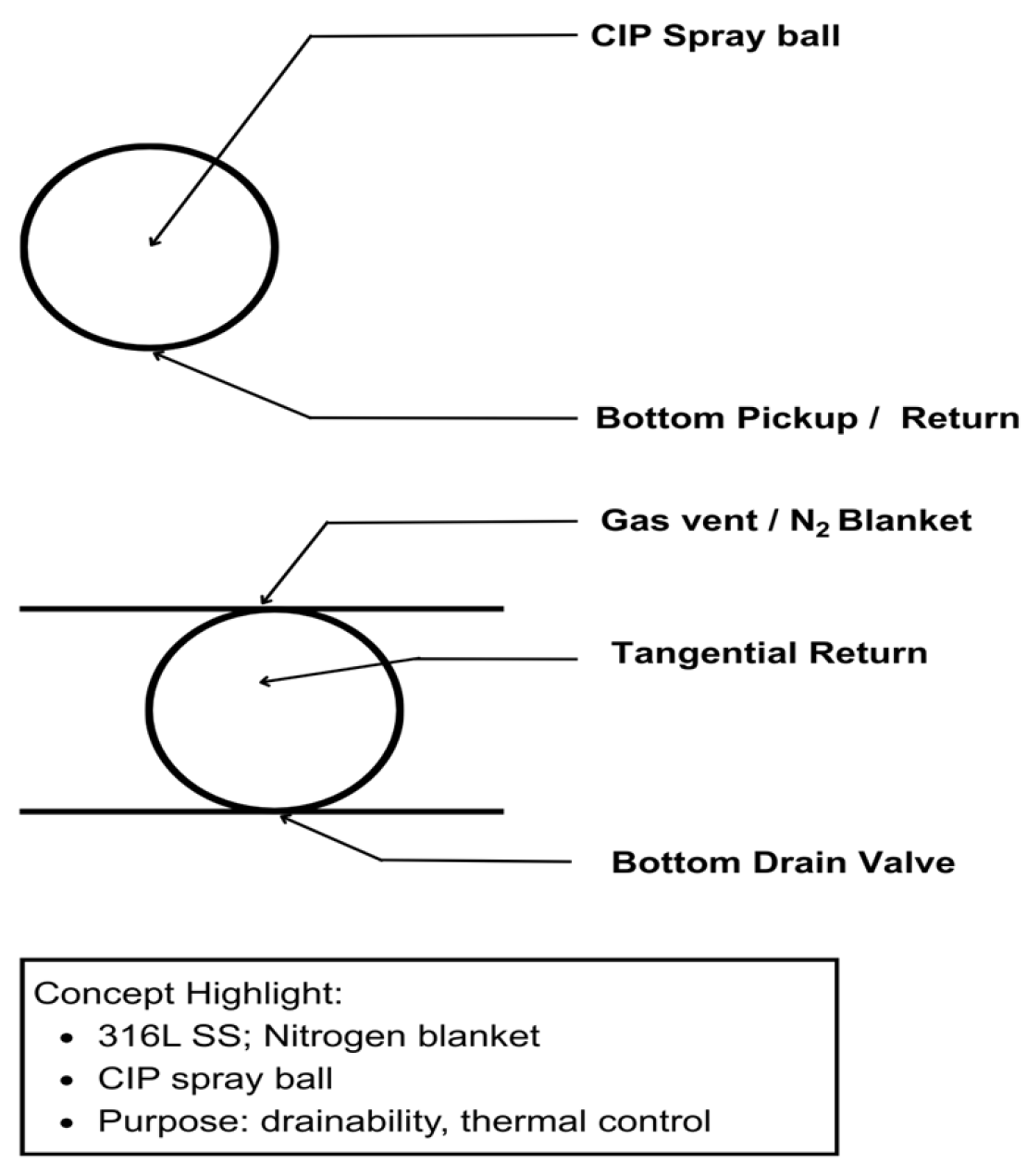
Figure 1. Conceptual stainless-steel vessel schematic showing CIP spray ball, nitrogen vent, tangential return, and bottom drain, emphasizing drainability, cleaning efficiency, and thermal control.
Eng 06 00275 g001
Figure 2. Conceptual diagram of a logistics and transport model for stainless-steel tank systems, highlighting critical components including the tank mounting frame for secure chassis integration, the manway/valve for operational access and refueling, and the saddle supports that distribute loads and minimize vibration stresses during transit.
Eng 06 00275 g002
Figure 3. Presents photographs of stainless-steel bulk materials, specifically grades 316 (left) and 304L (right). These 3D images were captured directly from the factory immediately after the first annealing stage, highlighting the distinct surface appearance of the alloys at this point in production.
Eng 06 00275 g003
Figure 4. The first Annealing Temperature curve of the stainless-steel materials 316 and 304L.
Eng 06 00275 g004
Figure 5. From left to right: geometric configuration of the specimens (20 mm × 20 mm) before and after polishing (center), and schematic illustration (right) showing the red-marked spot where samples were extracted from the bulk materials, at 0.5 radius along the longitudinal direction.
Eng 06 00275 g005
Figure 6. (a): Niton XL2 XRF Analyzer used for elemental analysis of the stainless-steel samples; (b) Bench furnace used for isothermal annealing at 700 °C for 1 h (photo sourced from the operating and instruction manual).
Eng 06 00275 g006
Figure 7. The EGM shows the literature review process. Rows correspond to different stages of article screening, while columns represent reasons for exclusion or inclusion. Shaded cells indicate the relative density of studies, showing where evidence exists and where gaps remain.
Eng 06 00275 g007
Figure 8. Workflow schematic illustrating the integration of systematic review, experimental characterization, and simulation/logistics modeling into a unified framework. The diagram highlights how literature evidence and material data converge into validated models for stainless-steel fluid storage tank logistics.
Eng 06 00275 g008
Figure 11. (a) 316 annealed at 1040 °C followed by water quenching, (b) 316 isothermal annealing at 700 °C for 1 h in a bench furnace, air cooling, (c) 304L annealed at 1040 °C followed by water quenching, and (d) isothermal annealing at 700 °C for 1 h in a bench furnace with air cooling.
Eng 06 00275 g011
Figure 12. Elemental weight percentage results of all the SS grades derived from X-ray fluorescence (XRF). (a) 316 annealed at 1040 °C followed by water quenching, (b) 316 isothermal annealing at 700 °C, (c) 304L annealed at 1040 °C followed by water quenching, and (d) 304L isothermal annealing at 700 °C.
Eng 06 00275 g012
Figure 13. Elemental weight percentage of all the SS sample grades derived from X-ray fluorescence.
Eng 06 00275 g013
Figure 14. EDS mapping Sample 304L annealed at 1040 °C followed by water quenching.
Eng 06 00275 g014
Table 2. Chemical compositions, w% (≤): calibration blocks.
AISI (UNS)Fe*CuCSiMnPSCrNiMo
316 (UNS S31600)-0.30.081.02.000.0450.03016.0–18.010.0–14.02.0–3.0
304L (UNS S30403)-0.30.031.02.000.0450.03018.0–20.08.0–12.00.40
Fe* constant.
Table 3. The sample labels and designations.
SampleAISI 316304L
As received, water quenchedA1B1
Heat-treated and air-cooledA2B2
Table 4. Alternative Expressions and Keywords for Logistics Models, Transport Models, and Stainless-steel Tanks.
Search AssistsLogistics Model Transport Model Stainless-Steel Tanks
Alternative expressionsVariables
Influencing factors
Gas transport
Gas flow
Fluid Transfer rate
Temperature
Heat exchange
Thermally induced.
Cryogenic
KeywordsOptimization
Variables
Gas storage and or Delivery
Gas transport
Flow-through system.
Location
Materials and experimental validation
Chemical or elemental compositions
Designed tanks.
Finite element method (FEM)
Table 5. Recent contributions (2024) to logistics and transport modeling and their implications for stainless-steel fluid storage tanks.
ReferenceFocus/ContributionKey InnovationRelevance to SS Tank Logistics
An et al. (2024) [23]Digital twin–based hydrogen refueling station safety model using CNN + 3D simulationIntegration of AI-driven decision-making with real-time digital twinsDemonstrates how digital twins and deep learning can be used for tank safety assessment and predictive modeling in hydrogen and cryogenic storage systems
Srinivasan et al. (2024) [24]Review of LNG supply chains: advances and opportunitiesComprehensive mapping of LNG logistics networks, highlighting optimization and decarbonizationExtends traditional models by embedding sustainability and network-wide efficiency, directly relevant to SS tanks for LNG transport
Al-Mohannadi et al. (2024) [29]Alternative fuels in sustainable logisticsIdentification of challenges and solutions for integrating alternative fuelsShows how fuel choices interact with logistics frameworks, relevant for SS tanks used in LNG/H2 transitions
Fariña et al. (2024) [30]Energy analysis of standardized shipping containersQuantitative assessment of thermal and energy performance in modular containersIllustrates how containerized designs and energy trade-offs can be applied to SS tank insulation and transport optimization
Table 6. The tank dimensions used for the case study.
Tank CapacityLength of the TankInner DiameterOuter DiameterInner Tank ThicknessOuter Tank ThicknessAerogel Layer ThicknessVacuum Gap Between Aerogel Layer and Outer Layer
50,000 m370 m25 m28 m40 mm40 mm1.25 m160 mm
Table 7. Temperature-dependent properties of stainless steels 304L and 316, aerogel insulation, and supports.
MaterialProperty293 K77 KNotes/Source
304L SSElastic modulus (GPa)~193~210Slight increase at cryogenic T [32]
304L SSThermal conductivity (W/m·K)~16~8Decreases with falling T [3,32]
304L SSCharpy toughness (J)~200<50Sharp reduction, embrittlement [16]
316 SSThermal expansion (µm/m·K)~16~9Reduced at cryogenic T [32]
316 SSSpecific heat (J/kg·K)~500~310Lower heat capacity at low T [32]
AerogelThermal conductivity (W/m·K)~0.020~0.012Consistent with cryogenic aerogel behavior [9]
GFRP supportsThermal conductivity (W/m·K)~0.3~0.12Reduced parasitic heat ingress [3]
Table 8. One-factor sensitivity (±25%).
ScenarioParameter Changes* (km)n* (≈)Facility Cost (USD/Day)Transport Cost (USD/Day)Total (USD/Day)
Baseline28.3714,00014,14228,142
Higher facility costF = 2500 (+25%)31.6615,00015,81130,811
Lower facility costF = 1500 (−25%)24.5812,00012,24824,248
Higher transport costcₜ = 0.025 (+25%)25.3816,00015,81131,811
Lower transport costcₜ = 0.015 (−25%)32.7612,00012,24724,247
Higher demand densityλ = 625 (+25%)25.3816,00015,81131,811
Lower demand densityλ =375 (−25%)32.7612,00012,24724,247
* means constant.
Table 9. Descriptive Statistics (All Specimens, n = 4).
ElementMean (wt.%)SD95% CIn
Cr17.420.5216.59–18.244
Ni9.321.247.35–11.294
Mn1.860.241.47–2.254
Mo1.260.92−0.20–2.724
Cu0.430.170.15–0.704
Replicated XRF measurements across specimens A1, A2, B1, and B2 yielded the above mean compositions (±SD, with 95% CI). These intervals quantify variability and confirm that Cr, Ni, and Mn remain within expected engineering ranges, while Mo and Cu exhibit higher dispersion.
Table 10. Group Comparisons (A vs. B Specimens, n = 2 each).
ElementGroup A MeanGroup B MeanDifference (B−A)Hedges’ gEffect Size
Cr17.0217.82+0.80+1.61Large
Ni10.388.27−2.11−4.71Very large
Mn1.682.05+0.37+1.50Large
Mo2.050.47−1.58−7.30Very large
Cu0.300.56+0.27+1.51Large
Grouped comparisons (A = A1 − A2; B = B1 − B2) reveal systematic differences between the two sets. Notably, Ni and Mo are substantially higher in Group A, while Mn and Cu are higher in Group B, with Cr slightly elevated. Effect sizes (Hedges’ g) confirm that these differences are statistically large to very large.
Table 11. Representative EDS/XRF compositions of stainless steels 316 and 304L after 700 °C annealing (mean of replicate spectra). Results reported in wt.% and at%; uncertainties given as ±SD with 95% confidence intervals. Values below the detection limit are marked <LOD.
Element316 (wt.%)316 (at%)304L (wt.%)304L (at%)Typical 95% CI (wt.%)LOD (wt.%)
Cr17.6 ± 0.518.917.2 ± 0.418.416.8–18.40.1
Ni10.1 ± 0.69.18.3 ± 0.57.57.5–10.80.2
Mn1.7 ± 0.21.92.0 ± 0.32.31.5–2.30.2
Mo2.0 ± 0.31.10.5 ± 0.10.30.3–2.30.3
Cu0.3 ± 0.10.20.6 ± 0.10.40.2–0.70.3
C<LOD<LOD<LOD<LOD0.5
Disclaimer/Publisher’s Note: The statements, opinions and data contained in all publications are solely those of the individual author(s) and contributor(s) and not of MDPI and/or the editor(s). MDPI and/or the editor(s) disclaim responsibility for any injury to people or property resulting from any ideas, methods, instructions or products referred to in the content.