1. Introduction
There is a need for energy resource augmentation and, at the same time, carbon emissions reduction. Electric vehicles have recently attracted the attention of automakers due to constraints on non-renewable energy sources and concerns over global warming. Switched Reluctance Motors (SRMs) provide an alternative to DC and AC motors. As opposed to DC and AC motor structures, which involve careful construction with rare earth materials, the SRM presents a simple structure since its construction does not involve brushes, rotor conductors, or magnets. It is therefore attractive for applications in automotive drives that require high performance. SRMs are preferred over DC and induction motors due to their high power density, high reliability, considerable construction cost, fault tolerance, and fast dynamic response. SRMs depend on sensing the energized stator pole for alignment with the rotor. Due to these exceptional properties, the SRM is finding industrial acceptance in control applications with considerable performance in dusty and harsh environments of high temperatures. Presently, high-power SRM drives are being developed for electric vehicles with promising features of suitable torque–speed ranges, efficiency, and power density [
1,
2].
In SRMs, the independence of the phase windings presents the possibility of independent current control per phase as a function of the rotor position [
3]. Theoretically, the rectangular waveform of the phase currents demands that power converters be utilized for the management of unidirectional and bidirectional currents per phase. To achieve efficient SRM performance, it is important that a suitable converter topology be selected [
4,
5,
6,
7,
8,
9]. Just like the permanent magnet synchronous motors (PMSMs), a suitable converter topology is needed before a direct connection is made between SRMs and the voltage supply. One of the most popular topologies for SRM drives is the Asymmetric Half-Bridge (AHB) converter [
10,
11,
12]. An AHB is designed with two switches and two freewheeling diodes for independent phase connections. However, in two-level converters, the standard conventional AHB converter is limited below given speed ranges and applications of low power demands [
3,
13,
14]. In [
3], the fault implications due to failure of the inner switches is addressed through current inversion. The method is, however, complicated and involves several redundant power semiconductor switches. The sizing of the split capacitors is also not addressed. Additionally, the rising-induced electromotive force during operation limits the current from reaching the base value at certain speeds. Therefore, wide-range and high-speed applications would require modified options of the AHB to guarantee excellent SRM performance. Currently, electric vehicle designs increase the DC-link voltage to a vary between 650 V and 900 V from the standard 400 V. Consequently, the converter voltage rating has to be increased. Disadvantages of semiconductor devices with higher power ratings include higher costs, increased size, and lower overall efficiency due to the slower response. To solve the listed challenges, multilevel converter topologies have been developed as an alternative [
15]. An improvement to [
15] is proposed in [
3]. In [
15], an NPC-AHB is presented for fault tolerance operation of the SRM. However, essential parts of voltage amplitudes are lost during failures due to open-circuit faults. The performance of the two topologies are compared for applications of high power and high voltages. The machine windings are still controllable even under multiple failure modes through other healthy switches. However, the topology demands a high number of power semiconductor devices to guarantee fault tolerance capability. The NPC topology proposed in [
15] performs satisfactorily for fault-tolerant operations. However, only half of the switches are able to withstand the effect of full DC-link voltage. An analytical comparison between an asymmetric MMC and a five-level NPC is presented in [
16]. Thus, by modifying the DC-link voltage to a multilevel configuration with an additional boost capability, the converter topology guarantees excellent overall performance [
16,
17].
Industrial applications have generally demanded for the design of fault-tolerant power converters. It is important that operations proceed safely in the event of one or more semiconductor device failures. For highly sensitive and safe critical industrial operations, fault-tolerant capabilities of the power converters must be taken into account. In [
18,
19,
20,
21], various power converters with fault-tolerant capabilities are discussed with regard to the speed control of industrial equipment. In the last decade, researchers have proposed various topologies for converter fault operations. In [
22], auxiliary diodes, mechanical switches, and two controlled insulated gate bipolar transistors (IGBTs) are utilized in independent isolation and with replacement of the faulty power semiconductor devices. Redundant power semiconductor devices are launched immediately when there is a fault, which are then subsequently short-circuited following the switching operation. However, this topology incurs high costs due to the high number of auxiliary diodes and mechanical switches. A fault-tolerant topology based on a classical AHB converter is proposed in [
23] for the control of a four-phase SRM. The author exploits the independent feature of the phases by connecting static switches out of sequence in the phases. The proposed method cannot be extended to odd-numbered SRM phases. Two of the AHB topologies coupled with various numbers of solid-state relays are proposed in [
24]. The converter cannot be scaled for more than three phase operations. To solve for the high number of power semiconductor devices and scalability, [
25] presents a fault-tolerant converter with a reduced number of switches and six-phase operation capability. However, the proposed topology presents poor faulty operations and cannot be utilized for more than six phases of SRMs.
Fault-tolerant solutions that do not involve auxiliary devices have also been studied. These solutions involve multilevel converter topologies such as the NPC-AHB and modular multilevel converters (MMCs). In this study, the DC-link voltage is not boosted. An NPC-AHB converter is developed in [
26]. The converter DC-link voltage is augmented with voltage-boosting capacitors. However, the proposed topology cannot be scaled to other SRM configurations apart from an 8/6 SRM system.
The contributions of this work include the design of a fault-tolerant multilevel converter with voltage boosting capacity for an in-wheel SRM system based on speed–torque characteristics. A 2D look-up table is utilized for different speed and loading conditions for the design of the in-wheel SRM. The proposed converter topology presents a combination and arrangement of a minimum number of power semiconductor switches feeding a direct-drive motor attached to a vehicle system for validation purposes. This article is arranged as follows: I. Introduction. II. Switched Reluctance Motor and the derivation of torque equations. III. Modeling of the EV and the in-wheel motor system. IV. The proposed converter topology and its operation modes under open-circuit fault scenarios. V. Simulation results.
2. Switched Reluctance Motor
Generally, fault tolerance capabilities of the SRM surpass those of other types of motors, thus guaranteeing high reliability for electric vehicle applications [
27]. Since there are no mutual couplings between the phases, as opposed to other types of motors, a fault on one phase of the SRM does not affect the operation of other phases. Fault isolation can be seamlessly achieved without affecting the other phases, due to magnetic independence of the phases. The SRM operates on the basis of variable reluctance. As current flows through the stator windings, individual phases are energized sequentially and torque is generated due to the movement of the rotor towards energized stator poles. Energized stator poles provide paths of minimum reluctance when aligned with the rotor pole. The torque generated is a function of the square of phase current and rotor position. Continuous torque is guaranteed through the synchronization of excited stator phases and rotor position.
The magnetic characteristic of the SRM is highly nonlinear, making its mathematical model complex. If the mutual inductance is neglected, for individual phase loops, voltage per phase is defined as
where
and
are the phase current, phase resistance, rotor position, and flux linkage, respectively. As the speed of the SRM increases, an induced emf develops and starts to oppose the change in phase current. Considering that the induced emf increases with the increase in speed, Equation (1) becomes
The last term on the right of Equation (2) corresponds to the induced emf as a function of rotor speed
. Therefore, to maintain the phase current values at high-speed operations, the supply voltage should be maintained at higher values beyond the rising emf magnitudes. This paper addresses this challenge by implementing a modified multilevel converter to help impose high values of DC-link voltage. Additionally, higher voltage values during phase excitation and de-excitation instances ensure minimum commutation periods between the phases. There is also a possibility of minimizing negative torque across the phases. For lower voltages, and therefore lower speeds, multilevel converters can help lower the switching frequency, thereby improving efficiency [
3].
The total torque developed is a summation of individual phase torques developed for every time instant. The relationship between the torque
and developed power
can be defined as
Therefore, the torque
T from Equation (3) simplifies to
where
is the stored magnetic energy and
is the output of mechanical power.
Substituting Equation (5) into Equation (4) yields the SRM torque as follows:
Equation (8) implies that the torque is also a function of rotor position and its value is independent of the direction of the phase current.
The magnetic characteristics of each phase of the SRM is independent of the other and this implies that the motor system can continue to operate even in the presence of partial faults in the converter unit. However, it is noted that the converter faults lead to undesirable speed variations and increased torque ripples.
4. The Proposed Converter Topology
The most conventional and reliably used converter is the AHB [
28]. This can be attributed to independent phase control and the three-level voltages it provides. However, the voltage levels are limited to 3 and it does not provide fault-tolerant capabilities. These limitations can be solved through the application of multilevel power converters. Several fault-tolerant converter topologies have been proposed by researchers in recent times. One of the most popular converters in fault tolerance research is the Neutral-Point-Clamped Asymmetric Half-Bridge Converter [
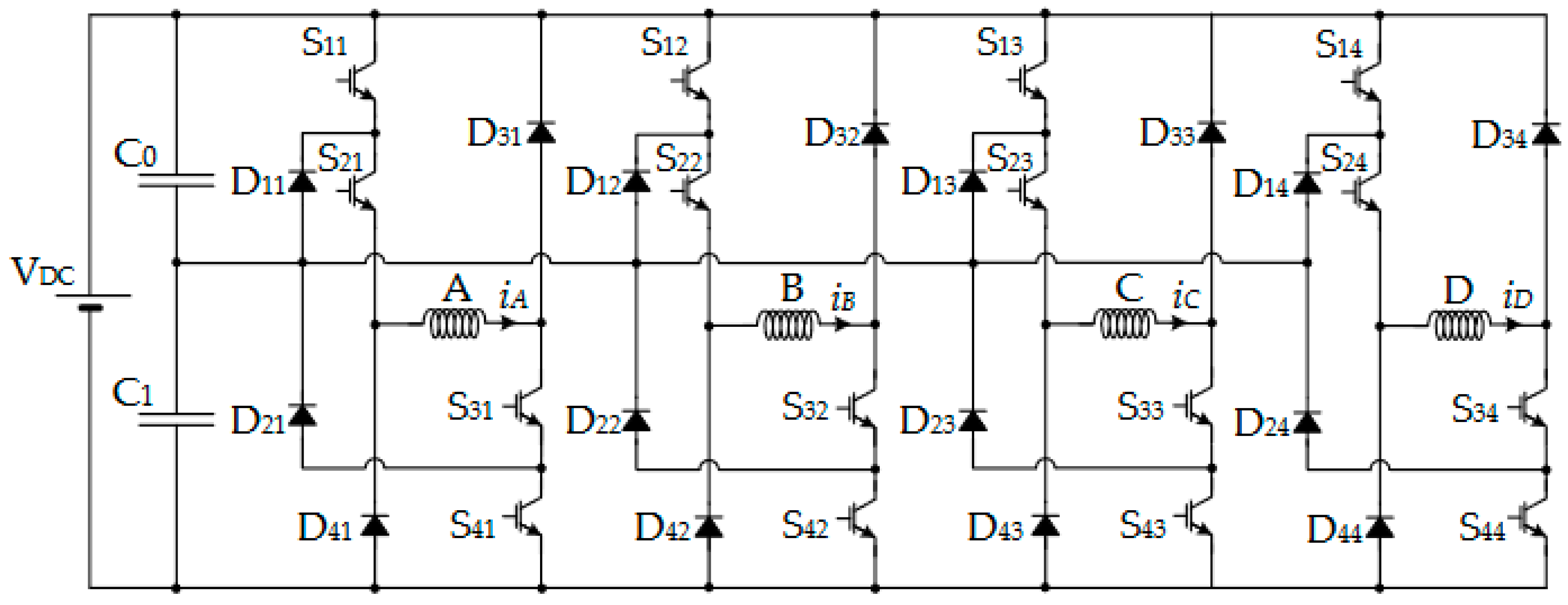
29]. A commonly used NPC-AHB converter structure is shown in
Figure 1 [
29]. This topology allows the application of more than three voltage levels to the windings.
This topology presents excellent demagnetization and magnetization characteristics. The DC-link capacitors store the demagnetization energy during phase de-energization; hence, the time taken for the current to fall decreases. These characteristics provide an extension of the positive torque range for the subsequent smaller operation in the region of negative torque. Besides increasing the DC-link voltage, the energy stored in the split capacitors feeds the incoming phases, thereby allowing the current to build up faster. This in turn causes the output power of the motor to increase. However, the conventional NPC-AHB converter topology presents undesirable behavior when the inner switches are subjected to open-circuit faults. In [
30], branch isolation of the affected leg is used through the utilization of several relays. The additional auxiliary switches and the power semiconductors introduce losses into the system, thus decreasing the system efficiency.
Sizing of the boosting capacitors
Sizing the DC-link boosting capacitors is highly significant in achieving overall efficiency and a wide range of operation speeds. Higher capacitance ensures that higher values of boosting voltages are provided to rapidly build up the current and then decrease it. Consequently, the base speed is increased. Maximum boost voltage levels are achieved through intricate sizing of the capacitors. Higher boosting voltages, however, imply an increased voltage rating of the semiconductor devices. Increased voltage ratings of the semiconductor devices in turn result in a slower response and higher costs of implementation. A smaller capacitance can be used to solve the challenges of cost and overall efficiency. However, undesirable performance will be presented when the motor operates beyond the base speed regions.
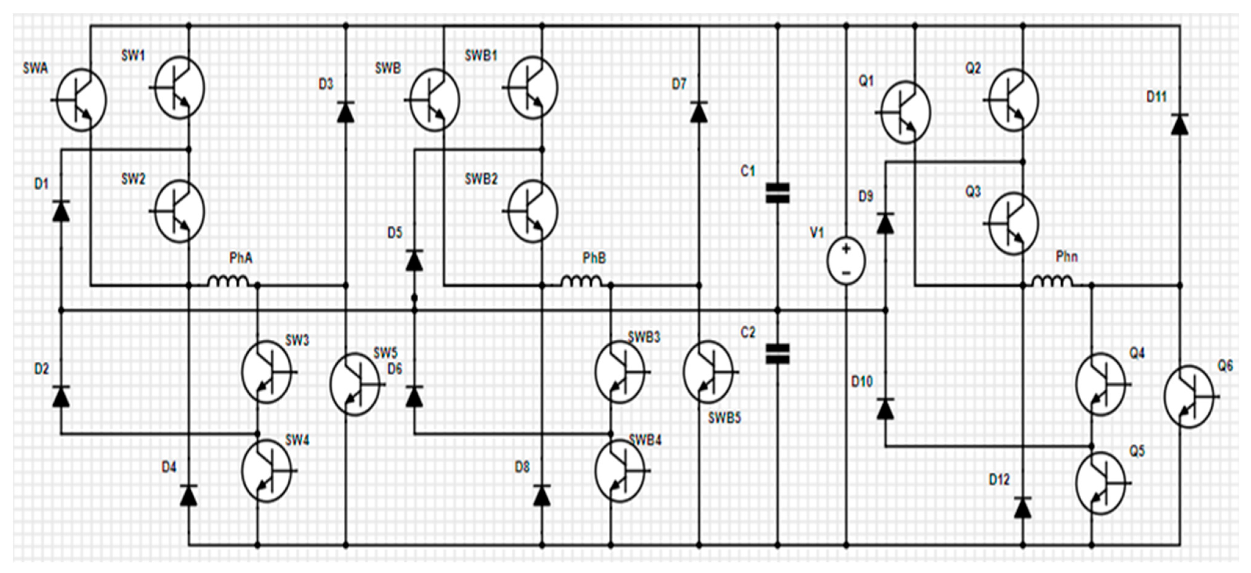
In this paper, the proposed multilevel converter is shown in
Figure 2. DC-link capacitors are connected after every two phases for voltage boosting and also proper demagnetization. The number of switches is reduced to 5 as opposed to 8 per phase. The capacitor values are chosen according to the capacitor sizing procedure covered in [
31].
where
is the initial current value in the phase winding,
is the DC-link voltage, and
is the sampling frequency. In this paper, the proposed multilevel converter was applied to control an 8/6 in-wheel SRM system but can be easily extended towards other SRM configurations.
4.1. Fault-Free Operation Mode
Considering phase A, and applicable to all other phases, the first voltage level, +
is achieved when switches SW1, SW2, SW3, and SW4/SW5 are turned ON. The capacitors help boost the quick development of the phase current to the reference current value. This in turn increases the power output of the SRM. The second voltage level
has the following switches ON within the loop of the upper capacitor: SW1, SW2, and SW3. The switches SWA and SWB to SWn are always OFF in motoring mode and provide the necessary redundancy. Moreover, with additional diode arrangements, the switches can be used for regeneration.
The third level,
is achieved when SW1, SW2, and SWA are ON, while SW3 and SW4 are OFF. The fourth level,
is attained through the turning ON of SW3 within the loop of the lower capacitor. Switches SW1, SW2, and SW4 are OFF for this level. The fifth level,
is realized when all the switches are OFF and the demagnetization current flows through the diodes, charging the capacitors in the process.
4.2. Fault-Tolerant Operation Mode
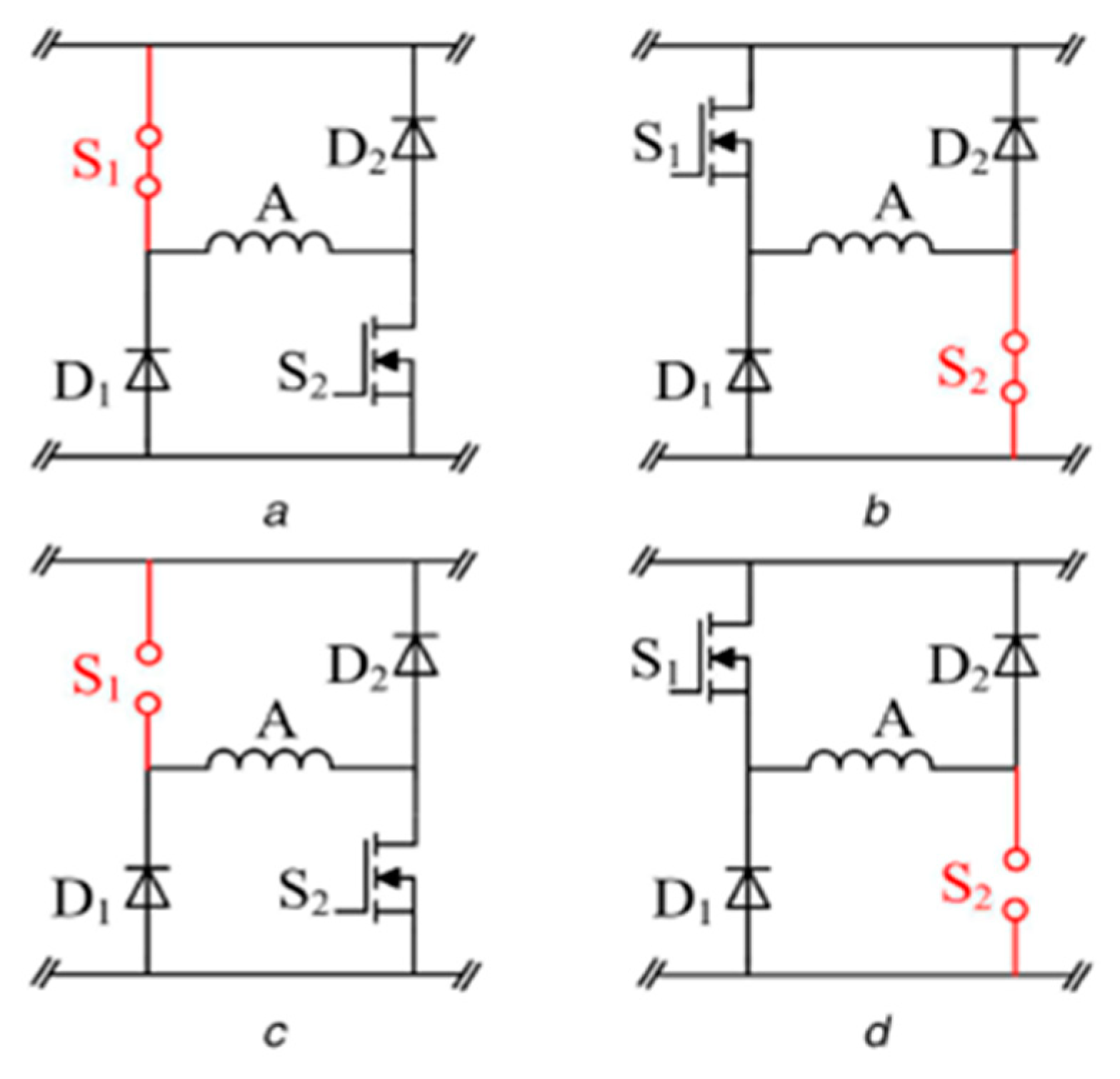
Power semiconductor failure affects the overall performance of the SRM motor. The common converter faults are the open-circuit and short-circuit faults, as depicted in
Figure 3 [
30]. An open-circuit fault can be introduced either in the outer or inner switches. The direct motor drive performance is investigated for open-circuit faults in the inner and outer power semiconductors. The open-circuit fault considered in this paper entails a loss of the whole power semiconductor from the converter leg. For the operation of the proposed converter under fault, the voltage balance is realized according to the method in [
30,
31].
5. Simulation Results
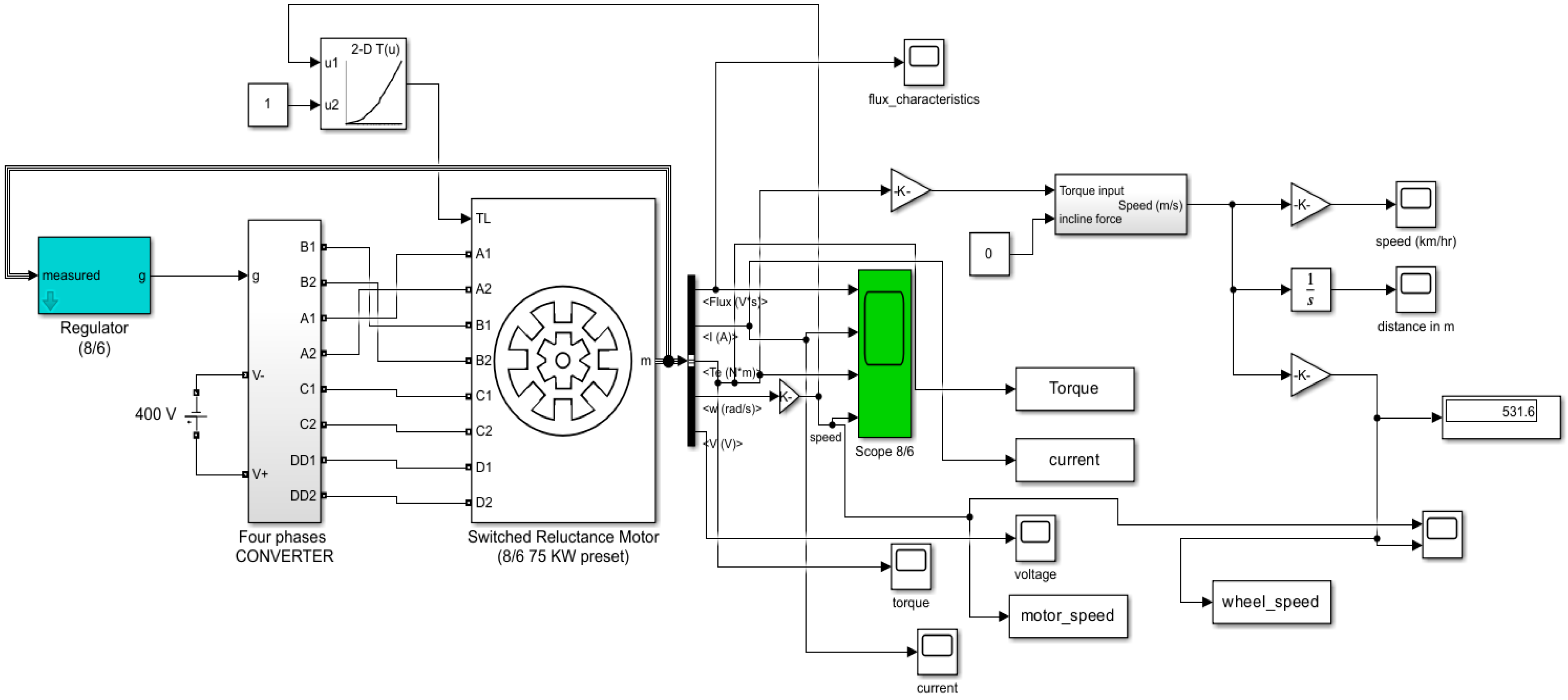
Figure 4 shows the Simulink block diagram with the proposed topology and the vehicle model.
For the EV model, the following parameters were used for simulations in Matlab/Simulink 2023b.
Wheel radius, r () = 0.3;
Vehicle mass, m () = 300;
Aerodynamic drag coefficient = 0.4;
Air mass density,
.
The proposed modified NPC-AHB topology feeds an 8/6 in-wheel SRM and is supplied by a 400 V DC source connected to 100
capacitors. The converter is implemented using IGBT devices in parallel with a series RC snubber resistance of 200 ohms and internal resistance of 0.001 ohms. The snubber capacitance is set to 0.1
, while the inductance is set to 0.
The direct motor drive speed and wheel speed are plotted in
Figure 5 for validation of the direct motor drive method. With motor torque as the input, the vehicle wheel system attached to the motor is able to smoothly track the direct motor speed under normal operations.
5.1. Performance Evaluation of a Conventional NPC-AHB Converter Topology
A conventional NPC-AHB was subjected to an open-circuit fault on the inner and outer power semiconductor switches.
Figure 6 shows the performance of the conventional NPC-AHB topology when both the inner and outer power semiconductor are lost through an open-circuit.
Due to the OC fault in the inner and outer power semiconductor devices, the in-wheel drive system and the vehicle experience prolonged transient periods, as shown in
Figure 6. Simulations for longer periods were performed for the OC scenario. It can be observed from
Figure 5 that tracking the in-wheel rpm is not realizable at higher speeds with a loss of more than two inner power semiconductors in one or more phases. In
Figure 7, flux is lost in one of the phases associated with the introduced fault at the beginning of the simulations.
Although no torque ripple mitigation method was used, higher torque ripples, according to
Figure 8, are experienced for the conventional NPC-AHB topology as compared to the torque output under the proposed converter topology.
The current behavior of
Figure 9 shows that the reference current is sustained for other phases even though the fault-associated phase has no current flow. Only three phases are registered out of the available four. The reference current was set to 50 A and a hysteresis controller was implemented for the control. The realization and maintenance of a higher starting current can be attributed to DC-link split capacitors.
5.2. Performance Evaluation of the Proposed Converter Topology
Fault-tolerant operation was realized through the combination and arrangement of power semiconductor devices in such a way that redundancy ensured system operation even under a loss of up to four devices, as depicted in
Figure 10,
Figure 11,
Figure 12 and
Figure 13.
6. Discussion and Comparative Analysis
The proposed topology was able to maintain current through all the phases even under a loss of semiconductor devices, as shown in
Figure 10. The current is also controlled well within the limits. The torque behavior in
Figure 11 shows better torque performance even under faulty operations for the proposed converter topology. The flux characteristics are presented in
Figure 12 for all the phases despite the presence of an OC fault.
The vehicle wheel is able to seamlessly track the speed of the direct-drive motor with the proposed converter topology, as shown in
Figure 13. A smooth transition is also observed as compared to those in
Figure 6 when OC fault scenarios are introduced in the inner power semiconductor devices.
Conventionally, the Asymmetric Half-Bridge (AHB) rectifier is the most commonly and reliably used [
28]. This can be attributed to independent phase control and the three-level voltages it provides. However, the voltage levels are limited to 3 and it does not provide fault-tolerant capabilities. The conventional NPC-AHB converter topology has been used in [
29,
30] for fault-tolerant purposes. The conventional NPC-AHB converter topology presents undesirable behavior when the inner switches are subjected to open-circuit faults. In this study, simulations were performed with the conventional NPC-AHB topology under open-circuit faults. It can be observed that the affected phase is lost, as shown in
Figure 7 and
Figure 9. In
Figure 8, a more negative torque is also registered for the conventional topology as compared to the torque output (
Figure 10) from the proposed topology. Finally, in
Figure 6, for the conventional NPC-AHB, tracking the in-wheel speed is not realizable at higher speeds with a loss of more than two inner power semiconductors in one or more phases.
Figure 13 shows that even with a loss of more than two inner power semiconductors, tracking the in-wheel speed is still possible even as the speed increases for the proposed topology.
7. Conclusions
Generally, increasing the induced electromotive force during SRM operation limits the current from reaching the base value at certain speeds. Therefore, wide-range and high-speed applications would require modified options of the AHB to guarantee excellent SRM performance in EVs. Higher capacitances have been utilized in recent developments for higher DC-link voltages. However, this calls for higher-voltage-rated semiconductor devices. The disadvantages of semiconductor devices with higher power ratings include higher costs, increased size, and lower overall efficiency due to a slower response. Currently, electric vehicle designs increase the DC-link voltage to a variation between 650 V and 900 V from the standard 400 V. Consequently, the converter voltage rating has to be increased. Further, EVs operate in harsh environments, which could potentially lead to converter faults and various electronic failure modes. To solve these challenges, a multilevel converter topology has been developed in this study as a potential application to SRM-driven electric vehicles. The proposed converter topology has been tested for open-circuit faults, and its performance has been investigated for torque and enhancements in performance at higher speeds.
A modified NPC-AHB was used to investigate the speed tracking of an in-wheel SRM with that of an electric vehicle wheel system. The proposed topology was tested for open-circuit faults in MATLAB/Simulink 2023b by removing the switches just before simulation. The removal of up to four switches represents a failure mode of the power semiconductors. The associated SRM winding to the removed semiconductors could not be magnetized, forcing the in-wheel drive to operate under the loss of given phases. Higher torque ripples were registered under circumstances of a lost phase. The vehicle speed is not able to track the in-wheel speed, as the speed increases further for the conventional NPC-AHB under open-circuit faults. For the proposed converter configuration, the loss of the inner or outer, or both, power semiconductors did not have any effect on the winding current interruptions and speed tracking of the in-wheel. Future work will involve experimental validation of the proposed topology. Additionally, speed controller and torque ripple mitigation strategies will be investigated for the proposed converter topology in various fault scenarios, including short-circuit scenarios.


