Article

Degradation Behavior of Glue-On Three-Dimensional Printed Plastic Horseshoes in Equine Stables

1
National Institute of Technology, Asahikawa College, 2-2-1-6 Shunko-dai, Asahikawa 071-8142, Japan
2
Japan Blood Horse Breeders’ Association, 517 Tahara, Shizunai, Shinhidaka 056-0144, Japan
3
National Institute of Technology, Tomakomai College, 443 Nishikioka, Tomakomai 059-1275, Japan
*
Author to whom correspondence should be addressed.
Eng 2023, 4(4), 2991-3006; https://doi.org/10.3390/eng4040168
Submission received: 3 November 2023 / Revised: 30 November 2023 / Accepted: 6 December 2023 / Published: 11 December 2023

Abstract

:
Hoof and leg problems in racehorses can cause serious injuries and decrease their value. Although therapeutic shoeing using special horseshoes can increase the effectiveness of veterinary care, it is labor-intensive and burdensome for farriers. A three-dimensional (3D) printed horseshoe fabricated by additive manufacturing has high design flexibility for use in special horseshoes. However, the mechanical properties of 3D printed plastics for use as horseshoes remain unclear. In this study, a proposed 3D printed plastic was subjected to degradation tests under the simulated equine growth environment, and changes in strength during the period of use were investigated. It was found that the strength of polylactic acid and polycarbonate, which are commonly used for 3D printing, was not significantly affected by the environment.

1. Introduction

Horseshoes are mainly shoed on racehorses to protect their hooves. Horseshoes are made by a farrier who forges a steel or aluminum alloy bar to fit each hoof. However, the ageing of farriers and shortage of workers in the near future are concerns in this field. Although off-the-shelf horseshoes made by press-forming or machining are often used, modifications by farriers are still needed to conform to the hoof shape. Lightweight soft-plastic horseshoes are also used for shock relief and treatment of hoof injuries. Plastic horseshoes are standardized industrial products with standardized sizes. Compared to general metal horseshoes, polyurethane, which is the most common material used for plastic horseshoes, is more difficult to modify during post-processing, posing difficulties in fitting into the hoof shape. Therefore, it is necessary to shape the hoof to fit into plastic horseshoes instead of normal hoof trimming. Another problem is the increasing cost of plastic horseshoes, which are more expensive than aluminum alloy horseshoes. Moreover, steel plates and wires are embedded within polyurethane horseshoes to improve their abrasion resistance, which is lower than that of metal horseshoes. Mischler and Hofmann [1] studied the wear behavior of commercial plastic horseshoes made of two polyurethane materials with different hardness values.
High loads, impact forces, and small repetitive loads acting on the horse’s limbs and hooves are major causes of injury. Horseshoeing for the purpose of shock mitigation and injury treatment is referred to as therapeutic shoeing [2]. There are several types of special horseshoes, such as roller-motion and rail shoes to promote breakover, and egg-bar horseshoes to distribute load and control sinking of the heel. The type of specialty horseshoe should be appropriately selected according to disease type. The effects of horseshoeing on the limbs and hooves of horses have been examined mechanically. Panagiotopoulou et al. [3] used finite element analysis to calculate the equivalent stress in the phalanges of the forelimb during walking, where higher stress was noted with a horseshoe. Tanaka et al. [4] corrected the contracted club foot of a thoroughbred by horseshoeing with a hinged aluminum horseshoe to increase the hoof size. O’Grady [5] reviewed studies on therapeutic shoeing. Horses that require therapeutic shoeing often have hoof problems that make nailing difficult. In such cases, the horseshoe is glued on the hoof using an acrylic adhesive that has been adjusted to have a short curing time and high toughness. However, the movements of the hoof-heel of metal horseshoes are restricted because the adhesive is applied to the entire hoof surface to prevent the shoe from being thrown, thereby negatively affecting hoof movements [6]. Hoof movement includes the deformation of the hoof during landing and serves an important function for the horse as it reduces landing shock and promotes blood flow, similar to a pump. The effect of horseshoeing on hoof movement has been studied by hoof-displacement-measurement experiments and finite element simulations. Bellenzani et al. [7] measured the strain of a bare foot at various running speeds. Reilly et al. [8] demonstrated the distortion of the lower hoof wall with nailing when hooves were glued with horseshoes for a long period. Hinterhofer et al. [9] applied cyclic vertical loads to simulate walking and used markers attached to the hoof to examine the effect of shoeing on hoof deformation using image analysis, noting that nailing obstructed the deformation of both the hoof wall and sole. Brunsting et al. [10] measured the heel displacement with a split-toe shoe, indicating that this special horseshoe did not interfere with hoof movements, as represented by similar displacement values with a bare foot. Although special horseshoes effectively treat diseases, their complicated shape, time-consuming manufacturing, and high cost are problems that ought to be addressed.
The application of three-dimensional (3D) printing as a manufacturing method for plastic parts with complex shapes is rapidly expanding. In particular, 3D printing is suitable for high-mix low-volume production with few shape restrictions because it can manufacture parts from the shape data designed by 3D computer-aided design (CAD) software without the use of molds [11]. 3D printers are classified based on the material used, namely metal powder or resin. Resin 3D printers include fused deposition modeling, optical fabrication, and an inkjet. The fused deposition modeling method is less expensive than other methods, and a wide variety of 3D printers and materials are readily available for this method owing to its widespread use over the past decade. In this method, a molten plastic filament is extruded and laminated on a heated platform. The price of the equipment for this technique has dropped drastically, to several hundreds of dollars since the patent’s expiration. Sood et al. [12] investigated the effect of printing parameters, such as layer thickness, orientation, and line width, on the tensile and impact strength. Dawoud et al. [13] evaluated the effect of the raster angle on the tensile, flexural, and impact strength.
By taking advantage of the ability of 3D printers to manufacture complex-shaped parts with high precision and without technical skills, the authors previously studied the application of 3D printing for the low-cost production of specialty plastic horseshoes [14]. The use of 3D printed horseshoes (3DPS) eliminates the disadvantages associated with the traditional use of specialty horseshoes. While a pair of commercially available urethane horseshoes costs about USD 60, the cost of the 3DPS material is about USD 20. Once a 3D model is made, any number of intricately shaped horseshoes can be printed with no trouble and easily replaced when damaged. The strength and wear resistance of 3DPS made of polylactic acid (PLA) and polyamide 6 were examined under room conditions [14]. It was found that the 3DPS did not fracture, even under a static compression load of 15,000 N, which is considered the maximum load applied to a hoof during galloping [15]. As such, a minimal negative effect on hoof movement is expected because Young’s modulus of the 3DPS is approximately equal to that of the hoof wall. Leonardi et al. [16] mounted a 3D printed PLA scaffold to a surgically resected hoof to compensate for a hoof defect for keratoma treatment. Although 3D printed tacks have been partially commercialized, their mechanical properties are rarely considered. In particular, mechanical properties are essential for outdoor use. The equine growth environment differs from that of the laboratory. Moreover, a 3DPS is strongly affected by the moisture of the bedding and track. In particular, the strength of plastic parts decreases when moisture is absorbed. Furthermore, PLA, which is often used in 3D printing, is biodegradable, reducing its strength. Goto et al. [17] investigated the relationship between the crystallization rate and degradation speed of PLA in water. Although Yaguchi et al. [18] previously investigated the decrease in strength of PLA specimens embedded in soil, the study focused on long periods with uncontrolled soil moisture content. Here, the degradation test considered the time period for horseshoe replacement as well as the soil moisture content of the equine growth environment.
In this study, special horseshoes were manufactured via 3D printing, and their dimensional accuracy, manufacturing time, and cost were evaluated. Subsequently, the fabricated 3DPS was glued on the hooves of thoroughbreds, and their damage after use was evaluated. An equine growth environment was reproduced in the laboratory, and the strength of the degraded plastic was evaluated via static tensile tests to investigate the strength reduction behavior of the 3DPS in detail.

2. Damage of the 3DPS after Use

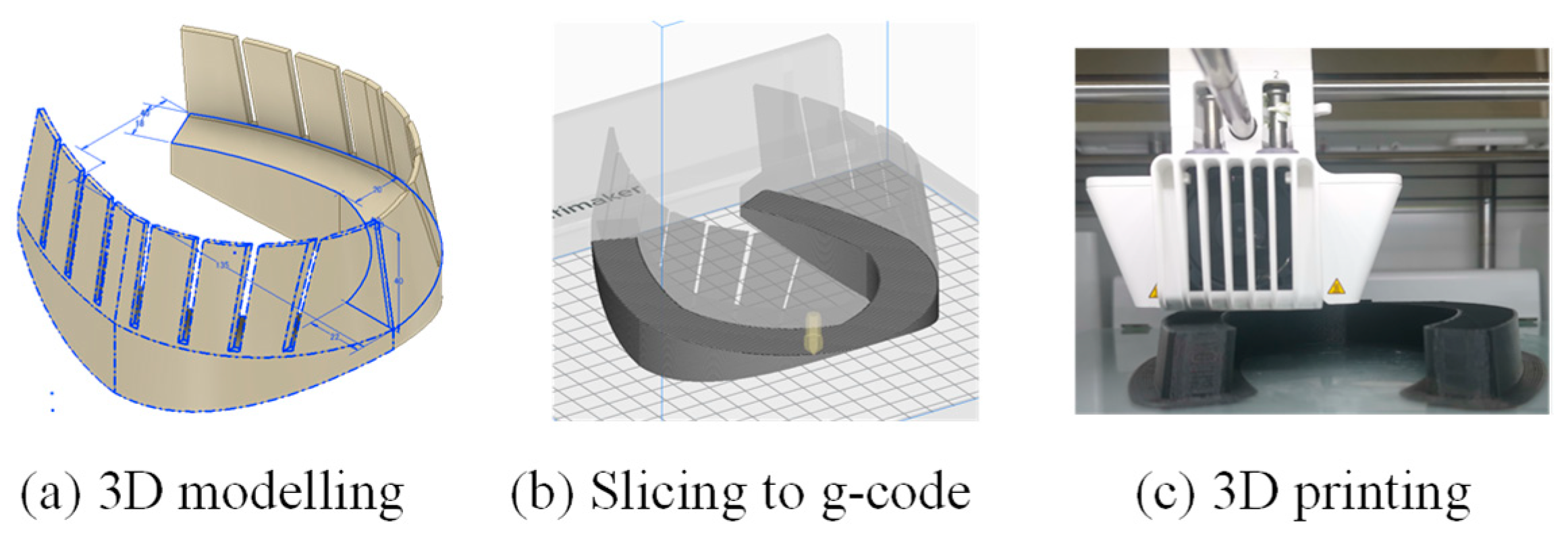
2.1. 3D Printing of the Glue-On Horseshoe

The 3D printing procedures of the 3DPS are illustrated in Figure 1. Three-dimensional CAD software was used to design the horseshoe. The 3D data from the 3D CAD software was converted into G-code, which is a format that can be used as the input for a 3D printer, using slicer software. The important parameters that affect the strength of the horseshoe, such as infill density and layer thickness, were determined by the slicer software. The 3DPS was shoed using a specialized glue for horseshoeing. Using this approach, anyone can print a horseshoe with a complex shape. Moreover, this increases the convenience of replacing damaged shoes, because multiple horseshoes of the same shape can be printed.

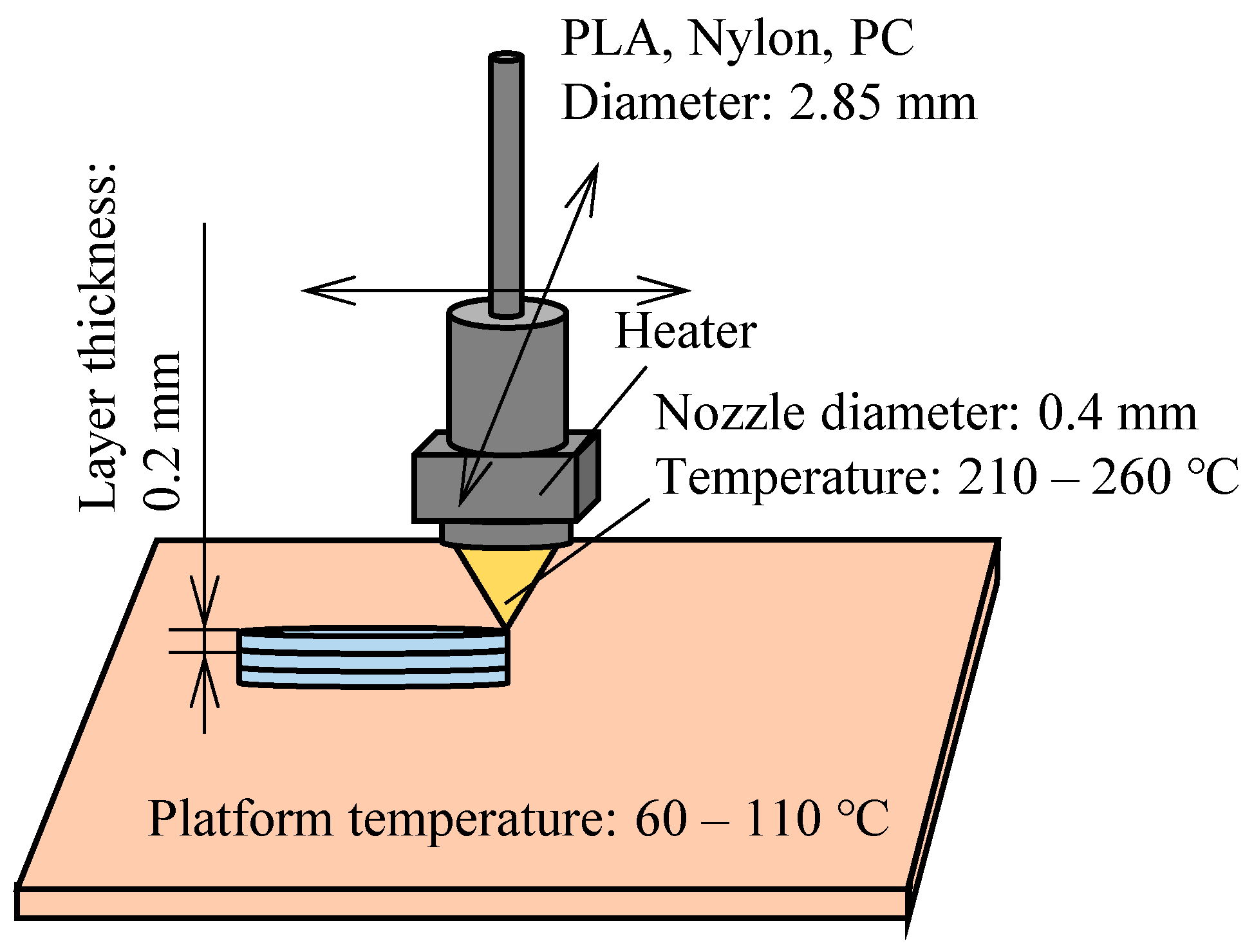
2.2. Conditions for the 3D Printing of the 3DPS

The conditions for the printing of the 3DPS are shown in Figure 2. Ulimaker S3 was employed for the 3D printing in this study. Different kinds of plastic filaments with a diameter of 2.85 mm were extruded through a heated nozzle with a tip diameter of 0.4 mm at 210–260 °C, and the molten plastic was laminated on a platform at 60–100 °C. The nozzle speed was 75–90 mm/s. The printing time of the general horseshoes was approximately 4 h to achieve an infill density of 100%.

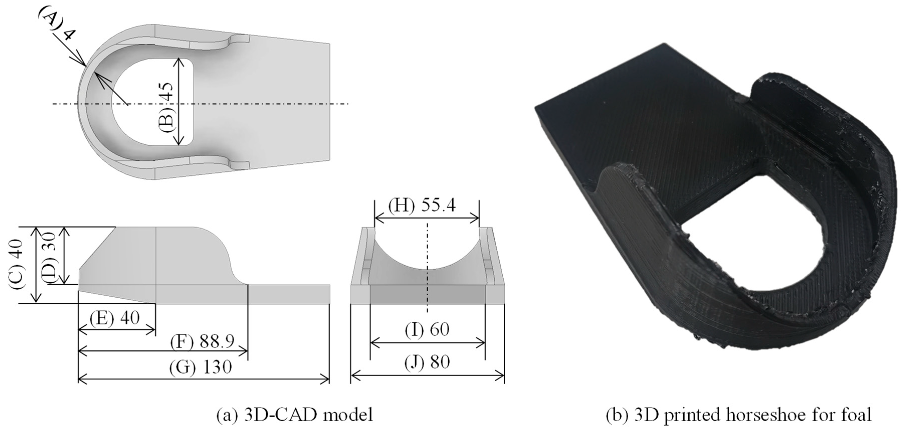
2.3. Dimensions of the 3DPS

The 3D CAD model of the 3DPS design, based on a limb-conformation correction horseshoe for a foal, and the 3DPS made of PLA are shown in Figure 3. The difference in the dimensions between the 3D model and the 3DPS is shown in Table 1. The tolerance of each dimension is approximately 2.5%, indicating the highly precise production of the 3DPS.

2.4. Damage of the Glued-On 3DPS after Use

The 3DPS was glued on a thoroughbred and used for two weeks, as shown in Figure 4. The following experiments were approved by the animal experiments committee at the Japan Racing Association, Hidaka Training and Research Center. The 3DPS was glued on the hooves of a yearling horse using an adhesive (Equilox I). This adhesive is an acrylic adhesive with a short curing time of approximately 10 min and a hardness close to that of the hoof wall after curing; it is used for bonding metallic horseshoes and for repairing hoof walls. After 14 days of use, the 3DPS exhibited severe deformation, abrasion, and staining. From the preliminary test results, the 3DPS made of PLA and acrylonitrile butadiene styrene was fractured in approximately 7 days. The adhesive did not detach from the hoof wall and the 3DPS was fractured, indicating that the adhesive strength was sufficient. This suggests that the strength of the 3DPS was only maintained for approximately 2 weeks due to the degradation during use. Therefore, degradation tests of the plastic used under an equine growth environment, i.e., an environment exposed to moisture, were conducted to clarify a suitable plastic material for the 3DPS.

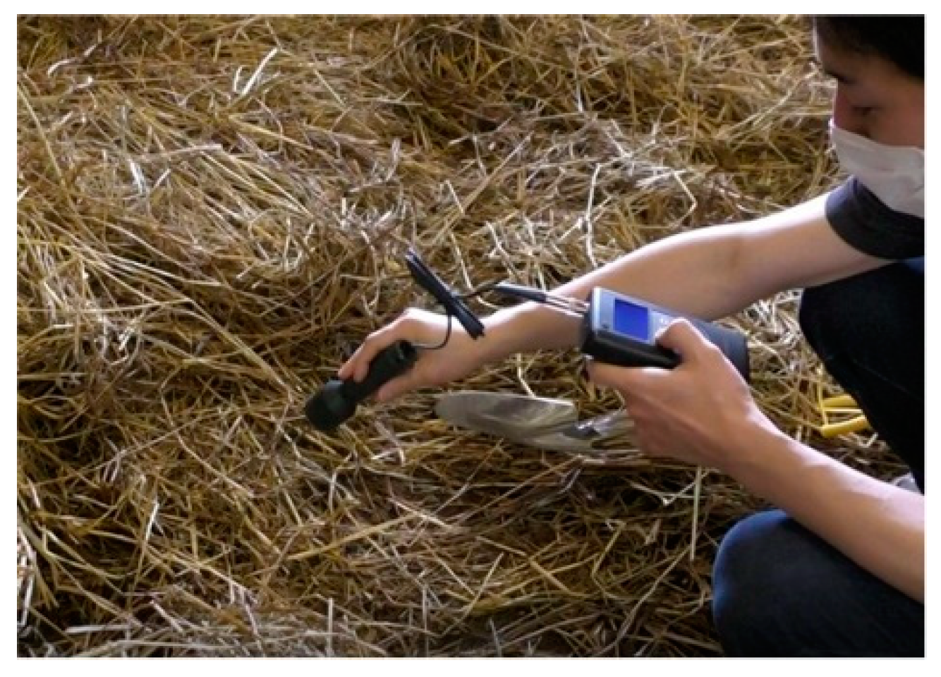
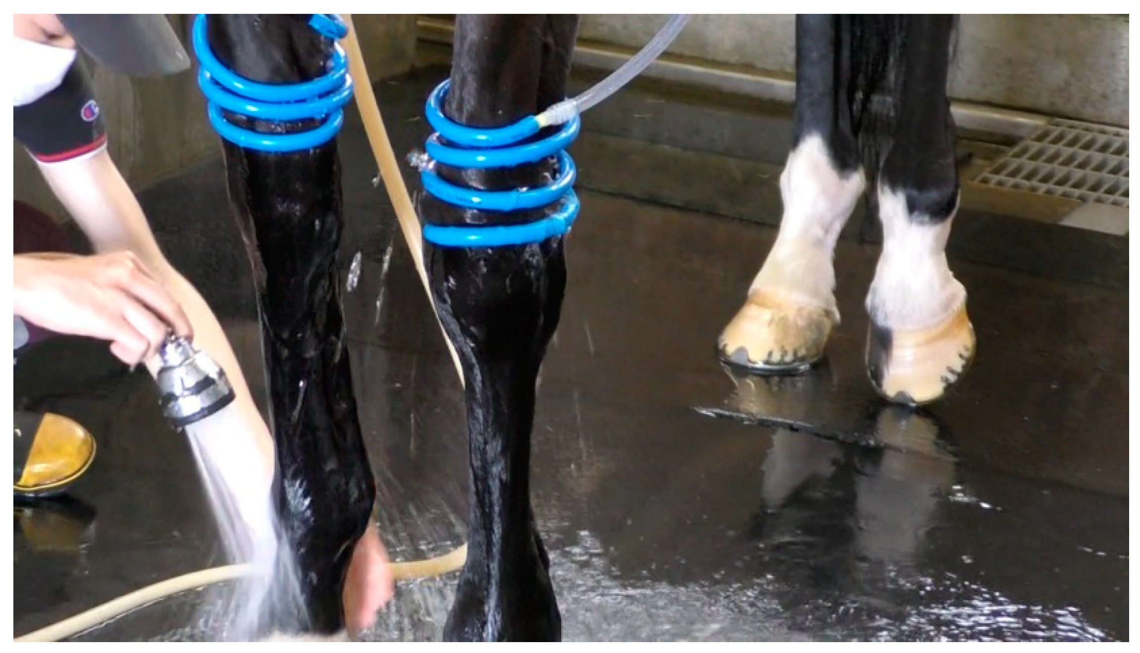
3. Investigation of the Equine Growth Environment

The equine growth environment was investigated, and degradation tests under a simulated growth environment in the laboratory were conducted to clarify the degradation behavior of the 3DPS during use. First, the environmental conditions in the stables and an arena were measured to examine the behavior of the horseshoes when exposed to water under the equine growth environment. The temperature and soil moisture of the stables and arena were measured at the Sapporo Racecourse Horse Riding Center, managed by the Japan Racing Association. The soil moisture was measured 10 times at each point using a moisture meter MC-7828OIL, as shown in Figure 5. This measuring equipment calculated the soil moisture content by measuring the electrical conductivity between two pins. The results of the environmental measurements in the stables and arena are shown in Table 2. The arena was sprinkled with water the day before, resulting in favorable conditions for exercise. The moisture content of the stables was measured before and after the straw was replaced. The straw used for one day had the highest moisture content, approximately 60%, which was simulated in the laboratory.
After exercise, the body of the horse was washed with a small amount warm water with a temperature of approximately 34.5 °C. The blue hose shown in Figure 6 was used to pour water over the legs for 30 min to reduce the temperature. The body of the horse was naturally dried outdoors; however, its hooves may not have been completely dried in this process.

4. Degradation Test Methods of the 3D Printed Plastic in the Laboratory

4.1. Simulation of the Equine Growth Environment

First, straw was used to simulate the stable environment in the laboratory, and the moisture content was measured. Dry straw with a weight of 219.0 g was spread to a thickness of 60 mm in a plastic case with a length of 238 mm, width of 358 mm, and height of 240 mm. Water was added until the moisture content reached approximately 60%. The relationship between the moisture content of the straw and measurement time is shown in Figure 7. The water content decreased to 35% in the first 10 h, demonstrating the difficulty in maintaining the moisture content for the 21-day continuous test using straw.
The straw dried quickly, which posed a difficulty in controlling the moisture content. As such, the specimens were degraded by embedding them in a pH-adjusted soil. The degradation test condition of the 3D printed plastic parts by embedding them in soil is shown in Figure 8. Approximately 15 L of soil was placed in a planter with a diameter of 400 mm, filled with water to achieve a moisture level of 60% ± 5%, and lime added to achieve a pH of 8–8.5. The specimens were completely covered with soil. The soil moisture was measured once a day, and approximately 250 mL water was added when the average moisture was below 55%. Based on the period of use of the horseshoe, one specimen was embedded per day for 21 days, and all tensile tests were performed on the same day. The relationship between the soil moisture and measurement time is shown in Figure 9. The water content at 60% ± 5% was maintained by adding water several times.
The specimens were submerged in water for 30 min and dried for 23.5 h for 21 days. The submergence test simulated the cooling of the horse’s legs, as shown in Figure 10. A plastic case with a size of 475 mm × 369 mm was filled with water, and the specimens were completely submerged in it. The number of specimens submerged in water was increased thrice a day. All tensile tests were conducted on the same day as the soil-embedding test. A thermometer (CENTER 300, Center Technology Corp., New Taipei City, Taiwan) was used to measure the water temperature.

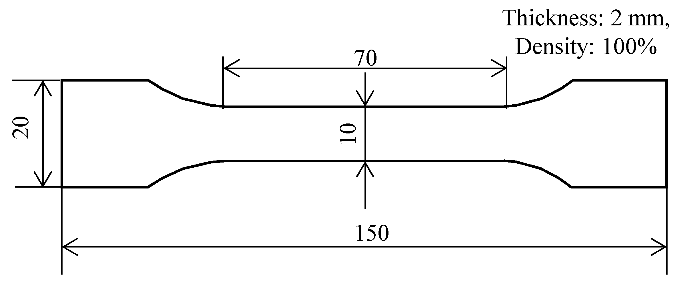
4.2. 3D Printing Conditions of the Tensile Specimens

The dimensions of the static tensile specimen are shown in Figure 11. PLA, polyamide (Nylon), and polycarbonate (PC) filaments were used and possess the characteristics of minimal errors, high abrasion resistance, and high strength, respectively. These three materials can be printed on low-cost 3D printers because the nozzle temperature is below 260 °C. PLA and PC have ester bonds, and Nylon has amide bonds, which react with water and hydrolyse, respectively. Ester-bonded resins react with strong alkali, causing degradation and cloudiness, whereas weak alkali, such as the soil in this experiment, do not cause problems. In contrast, nylon has a high chemical resistance to alkalinity. The layer thickness was 0.3 mm, and other conditions were the same as those presented in Section 2. The tensile specimen was designed based on JIS K 7152. It was printed with a total length of 150 mm, parallel-section length of 70 mm, parallel-section width of 10 mm, and thickness of 2.0 mm.
A universal testing machine (SVZ-200NB-R3, maximum load: 2 kN) was used for the tensile tests, as shown in Figure 12. The tensile speed was set to 10 mm/min, and the test was terminated after fracture. The specimen placed under room conditions for 21 days was also examined for comparison with the results of the soil-embedding and submergence tests.

5. Results of the Degradation Tests of the 3D Printed Plastic

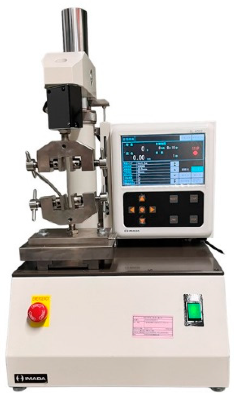
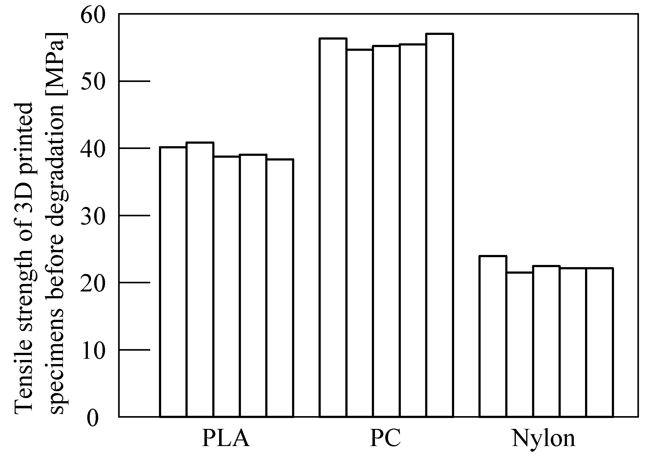
5.1. Tensile Strength of the 3D Printed Specimens
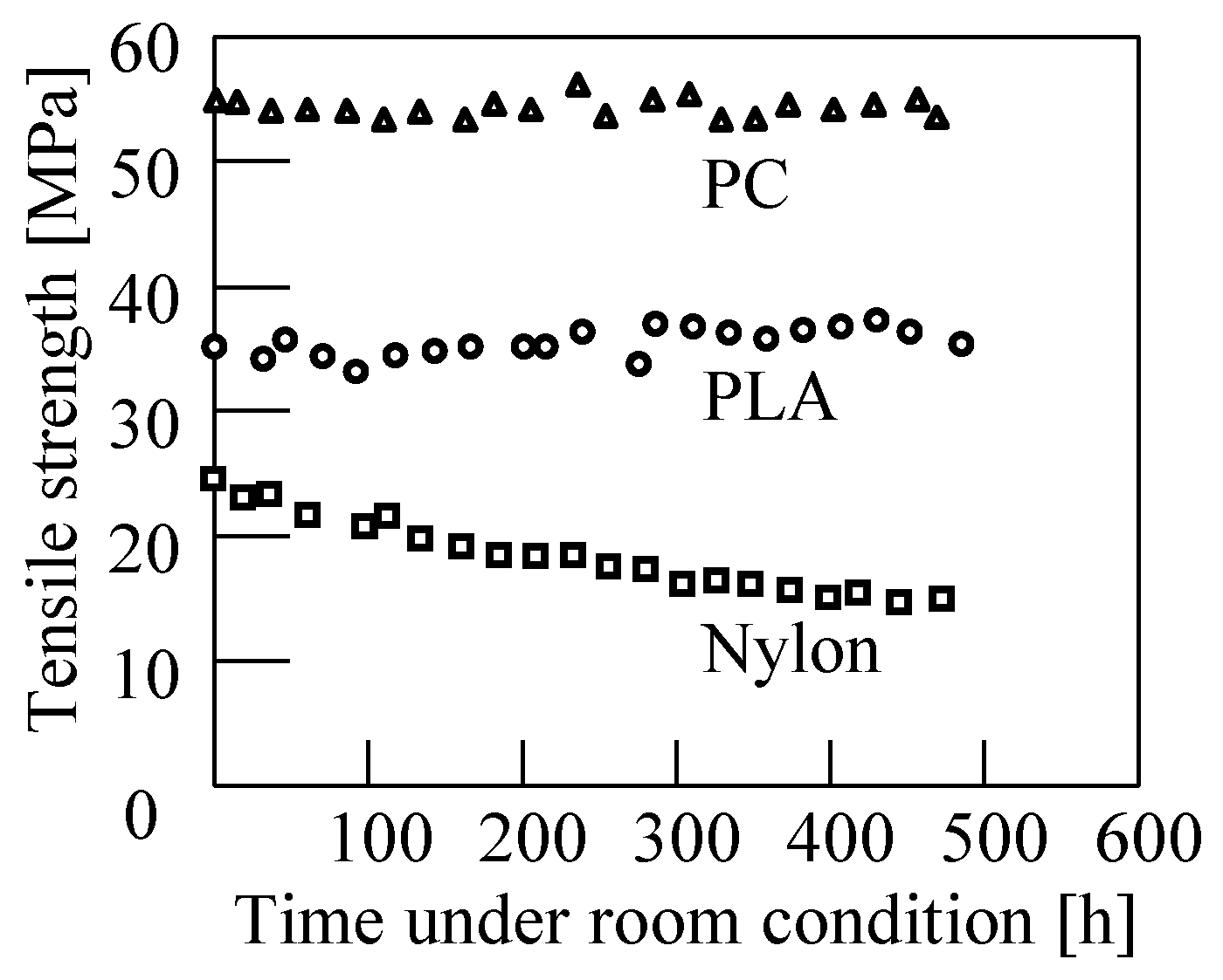
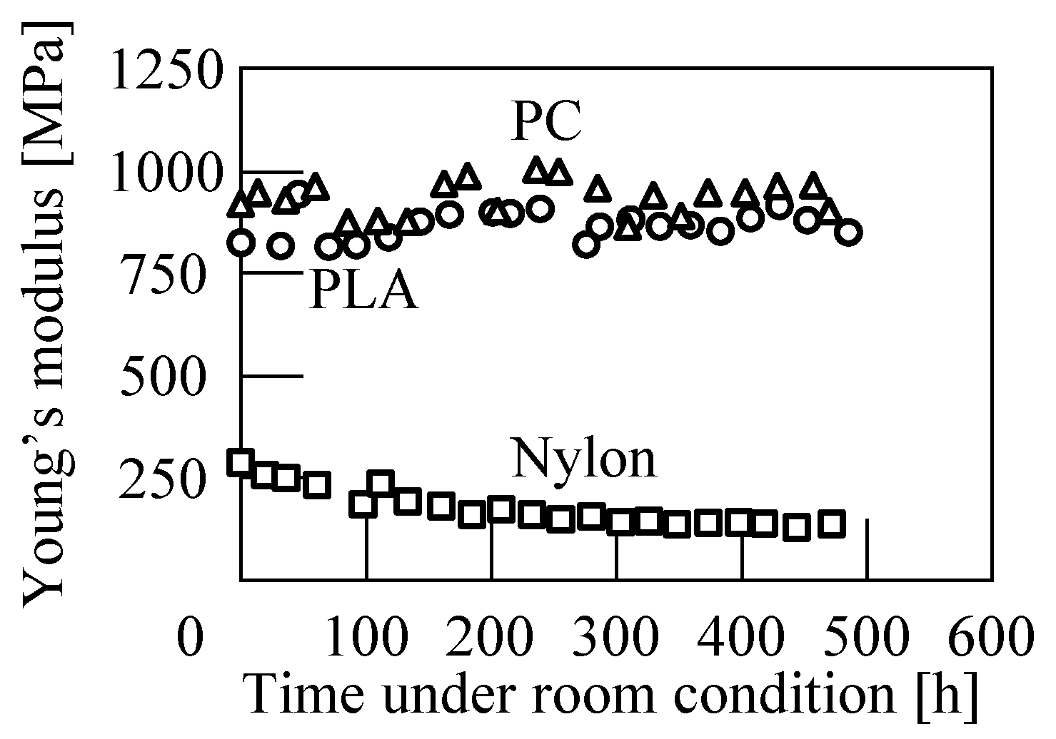
The tensile strength of the 3D printed specimens before degradation is shown in Figure 13. Five tensile tests were performed on each material. The difference between the maximum and minimum tensile strengths of PLA, PC, and nylon was approximately 2.5 MPa, which is ascribed to variations during printing.

5.2. Room Condtions

As plastic is degraded by the moisture in air, the specimens were placed under room conditions for up to 21 days. The variations in the stress–strain relationship under room conditions is shown in Figure 14. The slope of the PLA specimen in the elastic region on the 10th day was larger than that on the 1st day and did not change considerably thereafter. The PC specimen maintained its strength in this period. The maximum stress of the nylon specimen decreased on the 10th day, followed by a slight decrease after the 10th day. Approximately half of the changes were observed from the 1st day to the 10th day.
The relationships between the tensile strength and Young’s modulus and time under room conditions are given in Figure 15 and Figure 16, respectively. The Young’s modulus is calculated by the following equation:
E = σ 0.025 σ 0.005 ε 0.025 ε 0.005
where σ0.025 and σ0.005 are the tensile stress at the strain of ε0.025 and ε0.005, respectively. Almost no changes were noted in the tensile strength of the PLA and PC specimens, whereas the strength of the nylon specimen gradually decreased to 10 MPa on the 21st day. The Young’s modulus of the nylon specimens also decreased to approximately 150 MPa. Thus, the mechanical properties of nylon are affected by the moisture in the air.

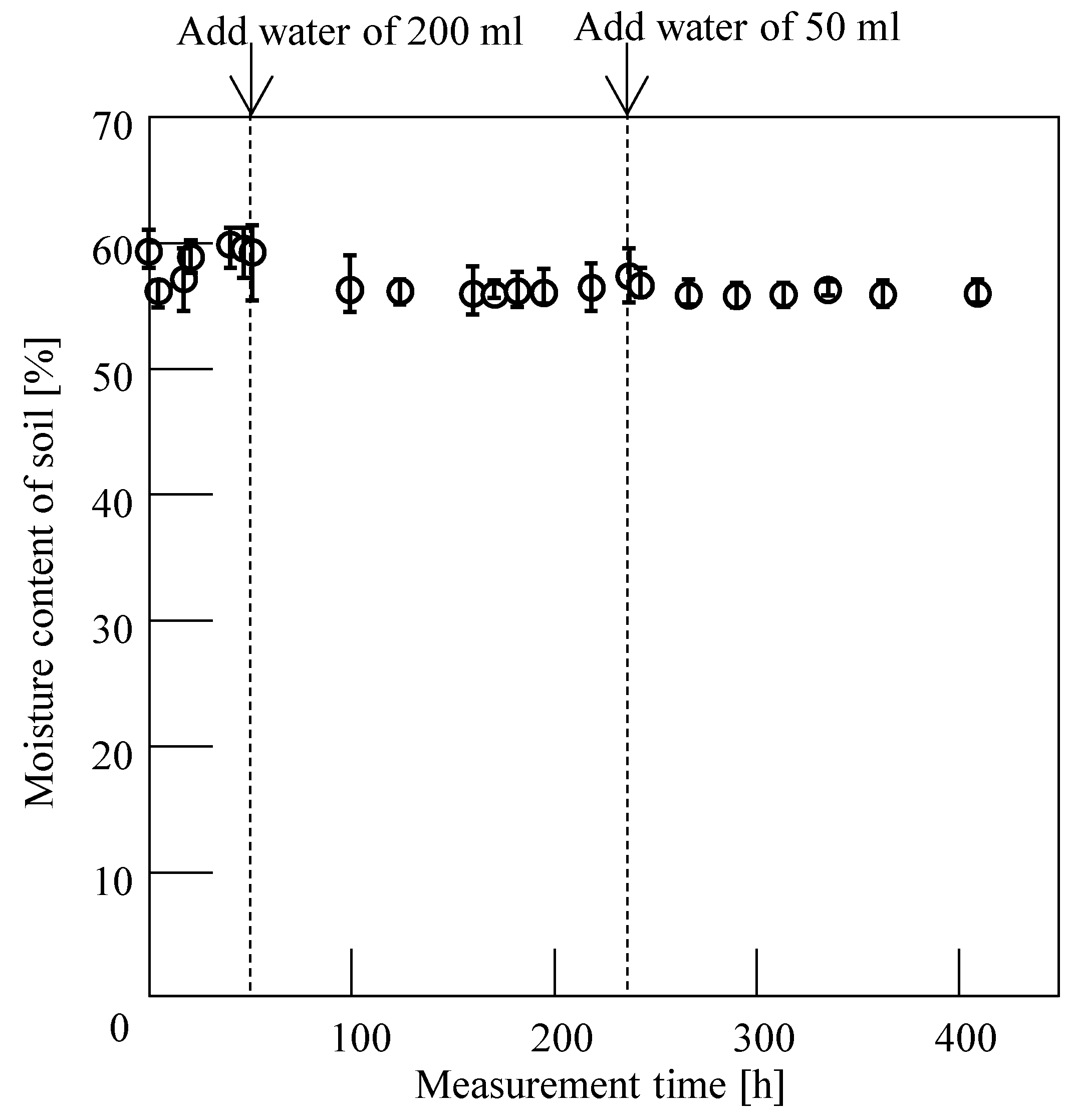
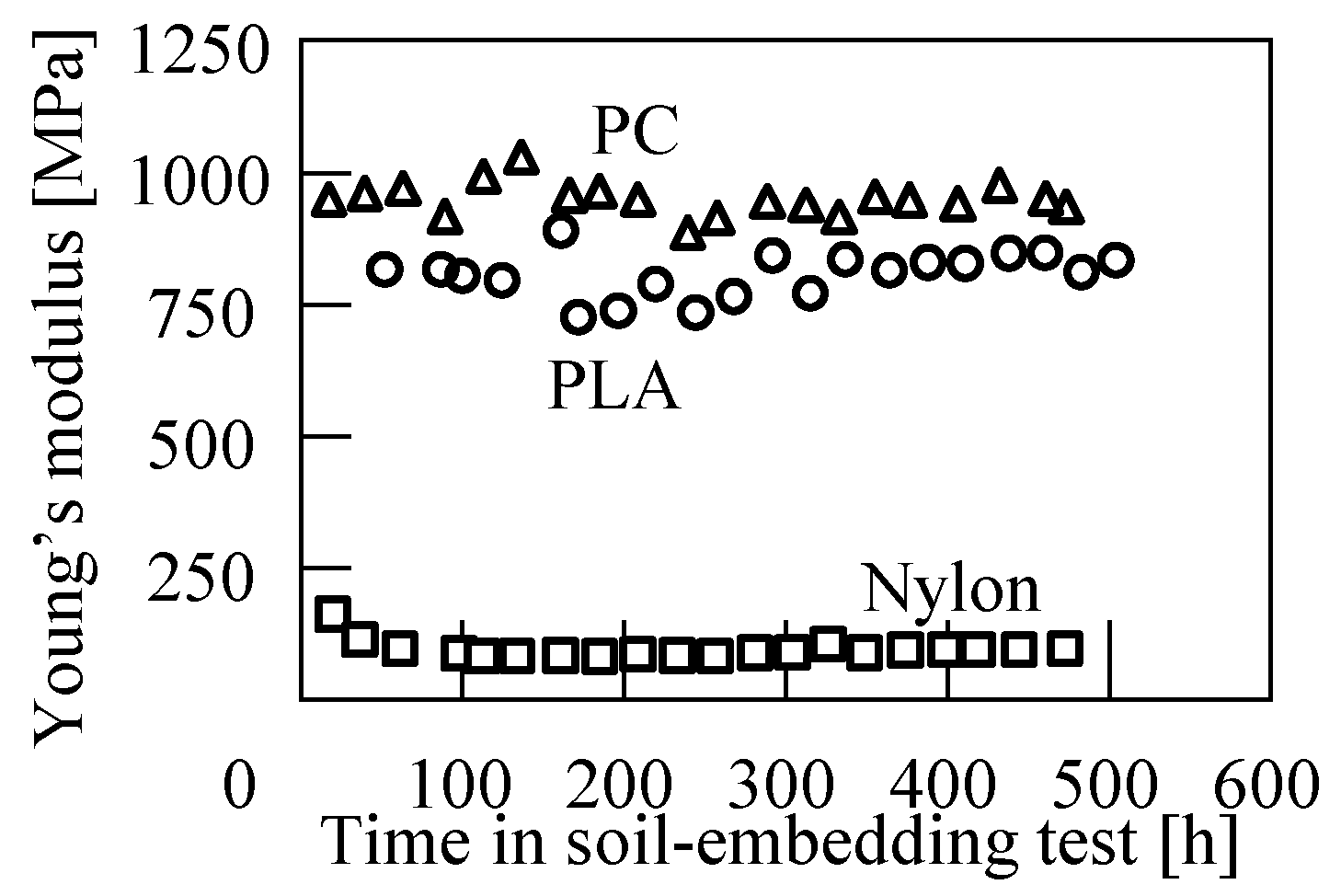
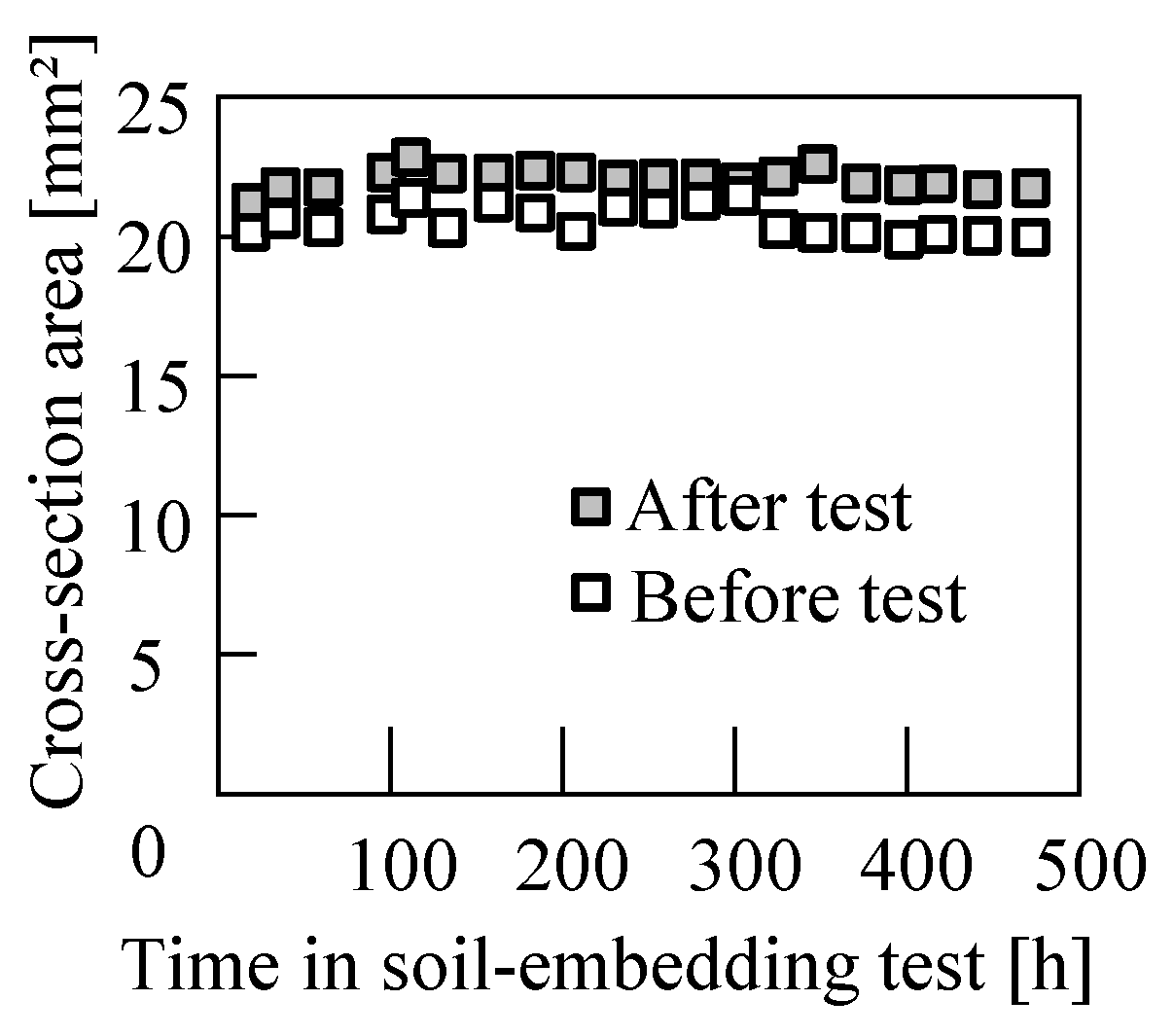
5.3. Soil-Embedding Test

The variation in the stress–strain relationship in the soil-embedding test is given in Figure 17. The stress of the nylon specimen decreased on the 10th day followed by a minimal decrease in the stress between the 10th and 21st days.
The relationship between tensile strength and time is shown in Figure 18. Although slight changes in strength were observed owing to variations in the PLA and PC specimens, as shown in Section 5.1, the strength did not change during the test period. The tensile strength of the nylon specimen drastically decreased by approximately 6 MPa from the 1st to the 4th day, followed by minimal changes.
The relationship between Young’s modulus and time in the soil-embedding test is shown in Figure 19. No changes were observed in both the PLA and PC specimens. Meanwhile, the Young’s modulus of the nylon specimen decreased greatly on the 1st day and then gradually decreased until the 3rd day. There was no significant change noted after the 4th day.
The relationship between the variations in the cross-section area of the nylon specimens and time in the soil-embedding test is shown in Figure 20. The cross-sectional area of the specimen after the soil-embedding test is higher than that before the test. The specimen expanded owing to absorption of the moisture from the soil.

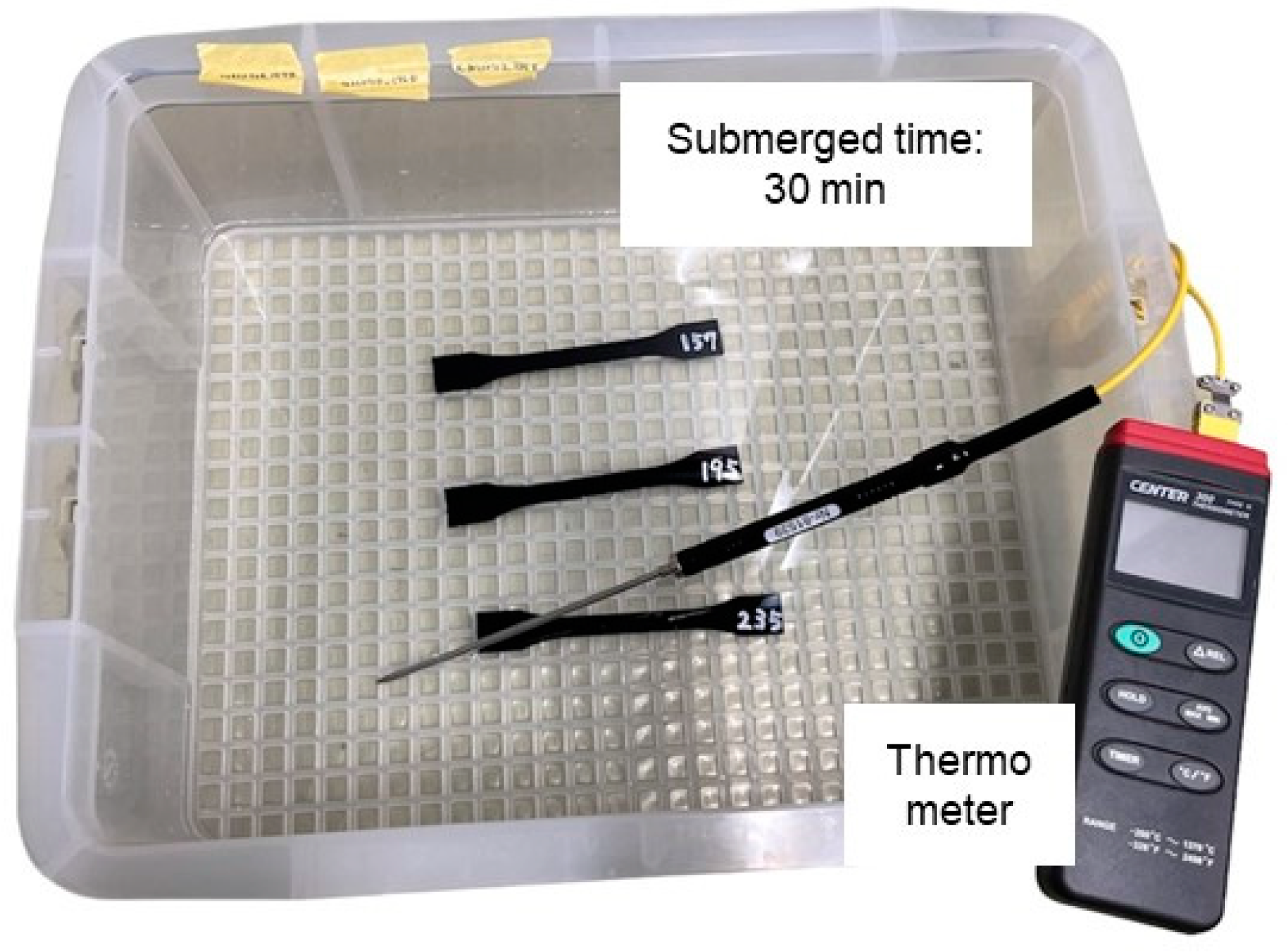
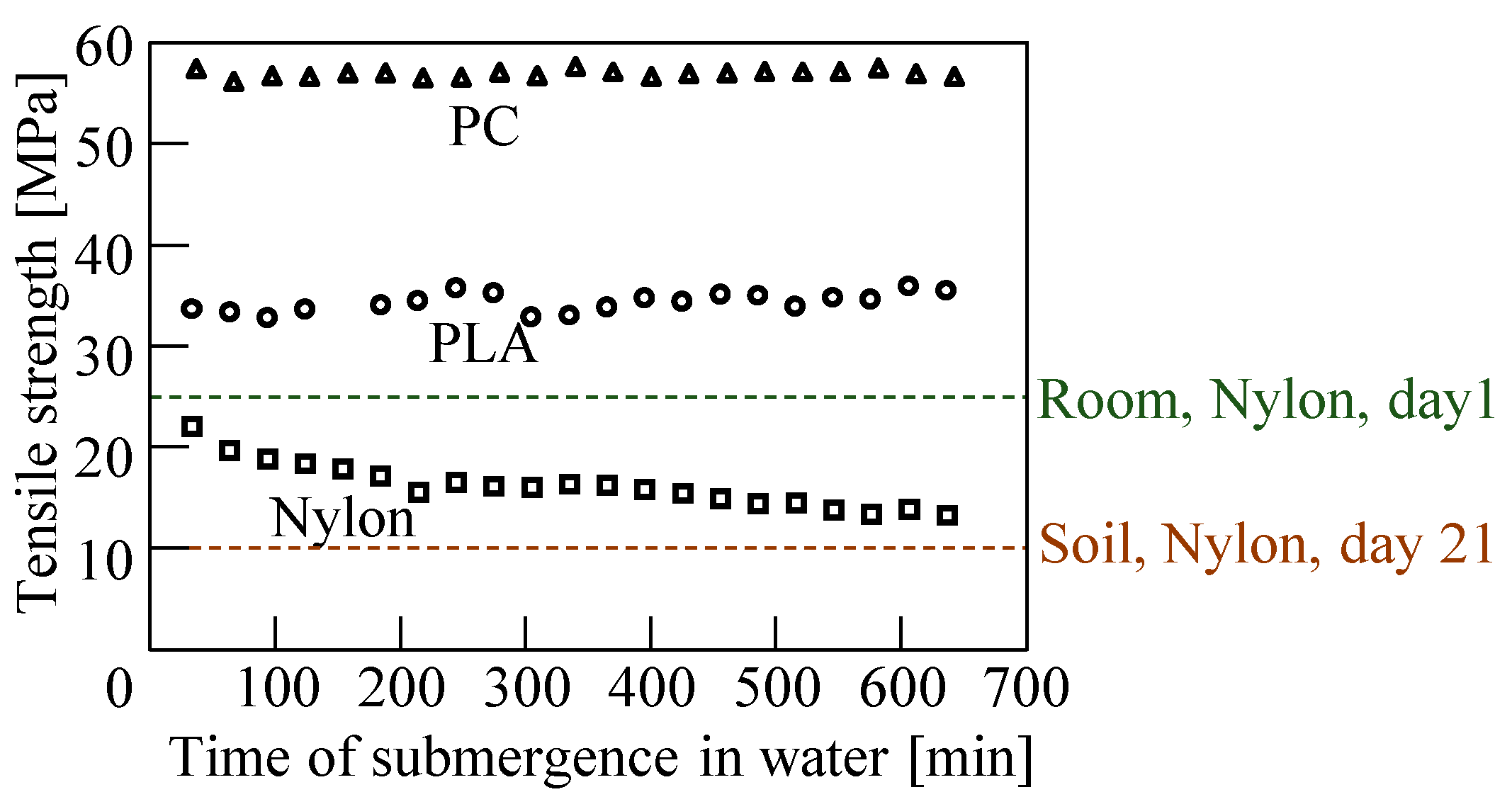
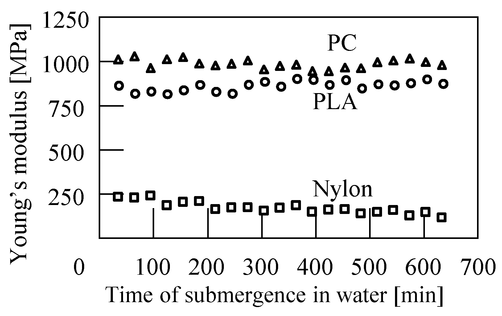
5.4. Submergence Test

The relationship between the tensile strength and time of submergence in water is shown in Figure 21. The water temperatures during the test were 21.4–24.2 °C, 21.5–23.3 °C, and 14.9–18.1 °C for PLA, nylon, and PC, respectively. Although minimal changes in the strength were observed in the PLA specimen, these changes were within the variations of the specimens, as clarified in Section 5.1. The tensile strength of the nylon specimen decreased by approximately 6.5 MPa from the 1st day to the 7th day and then gradually decreased by approximately 3 MPa until the end of the test.
The relationship between the Young’s modulus and time of submergence in water is shown in Figure 22. The Young’s modulus of the nylon specimen slowly decreased. The decrease in tensile strength and Young’s modulus was small compared to that of the soil-embedding test in Section 5.3. Therefore, the effect of soil moisture on the mechanical properties was greater than the effect of cooling.
The variations in the stress–strain relationship in the submergence test of the nylon specimen are given in Figure 23. The tensile test was performed thrice per day, resulting in minimal variations. The maximum stress of the nylon specimens decreased by approximately 40% on the 10th day. Although the maximum stress decreased slightly after the 10th day, it was approximately half of the amount of change from the 1st day to the 10th day.

6. Discussions

Three types of engineering plastics, PLA, Nylon, and PC, were selected as materials for the specimens because they can be printed on a low-cost 3D printer. Although nylon has excellent abrasion resistance, the strength of the specimens in the soil embedding test decreased significantly. The cross-sectional area of the nylon tensile specimen increased by approximately 20%, as shown in Figure 20. Assuming uniform expansion across thickness and width, the rate of dimensional change was approximately 2%, and the water absorption rate of the nylon at that time was estimated to be approximately 6%. The tensile strength and the Young’s modulus both decrease gradually with an increase in water absorption below 4% and level off above 4–5%. The water absorption property of nylon is expressed as a function proportional to the square root of time. The strength change in degradation tests showed a similar trend [19], suggesting that the decrease in strength shown in Figure 18 was due to water absorption. Moreover, this expansion might have led to a decrease in the bonding strength when the 3DPS was glued on the hoof, because the difference owing to the expansion of the plastic horseshoe and glue caused stress. Although variation in the mechanical and chemical properties of the 3D printed parts by water diffusion was investigated [20], anomalous time-dependent water diffusion characteristics for 3DPS could be caused by small cracks and exposure to moisture under large cyclic stress, which will be investigated in the future.
PLA and PC had low water absorption (0.2~0.3%), and changes in mechanical properties were quite small. The results of the study showed that PLA was not a problem after three weeks of use, even in a moisture-rich environment such as a horse stable. PLA could be degraded by microorganisms in the soil, resulting in a decrease in strength, however, it was found that even in a moisture-rich environment such as a horse stall, the strength was not affected after three weeks of use. Therefore, PLA or PC should be selected as a material for 3DPS. Although PLA has high 3D printing accuracy and fewer failures, printed parts are sensitive to impact force; meanwhile, PC has high thermal shrinkage, which makes it easy to peel off from the platform during printing, resulting in more printing failures, whereas the static and impact strength is high. In other words, 3D-printed PLA and PC parts have opposite properties.
The choice of which materials to use for 3DPS should be based on the weight and locomotion of the target horse, the speed of 3D printing, which is faster with PLA, the price of the material, and the dimensional accuracy. The applicability of each material to a 3DPS according to their characteristics is shown in Table 3. For example, PLA should be used for a horse that has difficulty walking due to hoof disease and requires little exercise, or for a light-weight foal, while a PC 3DPS should be used for a yearling that requires a lot of exercise and weighs more than 300 kg. Although broodmares require less exercise, they can weigh more than 700 kg during gestation, so the use of a 3DPS made of PC is recommended.
In order to establish a design guideline for the 3DPS, it is necessary to estimate the loads applied to the 3DPS during shoeing and conduct strength tests other than static tensile tests. An occurrence of fatigue failure is a strong concern because the 3DPS is repeatedly loaded with forces that cause it to open and close in the horizontal direction, as well as compressive forces, just by walking. In addition, an evaluation of the durability of the 3DPS for shoeing of various horses’ weights and diseases, and testing without shoeing the 3DPS for comparison, is needed. The strength of the material used in this study limits the use of 3DPS to therapeutic shoeing, whereas the use of super engineering plastics such as CFRP has the potential to expand the application for racing. Horseshoes for racing are generally made of aluminum alloy, and if they could be replaced with plastic, the weight could be reduced to less than half, reducing the burden on the limb. However, cost, and the change in running form due to the change in weight of the horseshoes, should be taken into consideration. These subjects will be the target of our future work.

7. Conclusions

In this study, 3D printed tensile specimens made of three types of plastics were degraded under an equine growth environment simulated in the laboratory to clarify the suitability of plastic materials for the 3DPS. The mechanical properties were obtained from the tensile test, and the following results were obtained:
(1).
The influence of room conditions, soil, and submergence in water on the mechanical properties of the 3D printed parts made of PLA and PC was minimal. Therefore, the amount of moisture in an equine growth environment can be ignored in the strength calculation of the horseshoe.
(2).
Both the strength and the Young’s modulus of the nylon specimens decreased in all the tests. The most notable changes were noted in the soil-embedding test.
(3).
Under room conditions, the strength of the nylon specimens decreased owing to degradation. As such, it has limited use in horseshoes, since it is necessary to anticipate the strength drop in the design of horseshoe using this material.

Author Contributions

Validation, D.K.; Investigation, K.Y. and S.-i.I.; Resources, D.K.; Writing—original draft, Y.N.; Writing—review & editing, Y.N.; Project administration, Y.N. All authors have read and agreed to the published version of the manuscript.

Funding

The research leading to these results received funding from the Japan Racing Horse Association.

Institutional Review Board Statement

The experiments in this study were approved by the animal experiments committee in Japan Racing Association, Hidaka Training and Research Center.

Informed Consent Statement

Not applicable.

Data Availability Statement

Data are contained within the article.

Conflicts of Interest

The authors declare that they have no conflict of interest.

References

  1. Mischler, S.; Hofmann, M. Wear of polymer horseshoes: A field investigation. Wear 2003, 255, 1300–1305. [Google Scholar] [CrossRef]
  2. Werner, H.W. The importance of therapeutic farriery in equine practice. In Therapeutic Farriery, An Issue of Veterinary Clinics: Equine Practice, 1st ed.; O’Grady, S.E., Parks, A.H., Eds.; Elsevier: Philadelphia, PA, USA, 2012; pp. 263–281. [Google Scholar]
  3. Panagiotopoulou, O.; Rankin, J.W.; Gatesy, S.M.; Hutchinson, J.R. A preliminary case study of the effect of shoe-wearing on the biomechanics of a horse’s foot. PeerJ 2016, 4, e2164. [Google Scholar] [CrossRef] [PubMed]
  4. Tanaka, K.; Hiraga, A.; Takahashi, T.; Kuwano, A.; Morrison, S.E. Effects of aluminum hinged shoes on the structure of contracted feet in Thoroughbred yearlings. J. Equine Sci. 2015, 26, 67–71. [Google Scholar] [CrossRef]
  5. O’Grady, S.E. Farriery for the foal: A review part 2: Therapeutic farriery. Equine Vet. Educ. 2020, 32, 580–589. [Google Scholar] [CrossRef]
  6. Yoshihara, E.; Takahashi, T.; Otsuka, N.; Isayama, T.; Tomiyama, T.; Hiraga, A.; Wada, S. Heel movement in horses: Comparison between glued and nailed horse shoes at different speeds. Equine Vet. J. 2010, 42, 431–435. [Google Scholar] [CrossRef] [PubMed]
  7. Bellenzani, M.C.R.; Merritt, J.S.; Clarke, S.; Davies, H.M.S. Investigation of forelimb hoof wall strains and hoof shape in unshod horses exercised on a treadmill at various speeds and gaits. Am. J. Vet. Res. 2012, 73, 1735–1741. [Google Scholar] [CrossRef] [PubMed]
  8. Reilly, P.T.; Reilly, D.A.; Orsini, J. The long-term results of glue-on shoes on dorsal hoof wall distortion. J. Equine Vet. Sci. 2009, 29, 115–117. [Google Scholar] [CrossRef]
  9. Hinterhofer, C.; Weißbacher, N.; Buchner, H.H.F.; Peham, C.; Stanek, C. Motion analysis of hoof wall, sole and frog under cyclic load in vitro: Deformation of the equine hoof shod with regular horse shoe, straight bar shoe and bare hoof. Pferdeheilkunde 2006, 22, 314–319. [Google Scholar] [CrossRef]
  10. Brunsting, J.; Dumoulin, M.; Oosterlinck, M.; Haspeslagh, M.; Lefère, L.; Pille, F. Can the hoof be shod without limiting the heel movement? A comparative study between barefoot, shoeing with conventional shoes and a split-toe shoe. Vet. J. 2019, 246, 7–11. [Google Scholar] [CrossRef] [PubMed]
  11. Schubert, C.; van Langeveld, M.C.; Donoso, L.A. Innovations in 3D printing: A 3D overview from optics to organs. Br. J. Ophthalmol. 2014, 98, 159–161. [Google Scholar] [CrossRef] [PubMed]
  12. Sood, A.K.; Ohdar, A.K.; Mahapatra, S.S. Parametric appraisal of mechanical property of fused deposition modelling processed parts. Mater. Des. 2009, 31, 287–295. [Google Scholar] [CrossRef]
  13. Dawoud, M.; Taha, I.; Ebeid, S.J. Behaviour of ABS: An experimental study using FDM and injection moulding techniques. J. Manuf. Proc. 2016, 21, 39–45. [Google Scholar] [CrossRef]
  14. Nakagawa, Y.; Ikeda, S.; Takazawa, K.; Yoshino, M. 3D printing ni yoru jushi teitetsu no seizou totokusei hyouka. Hippophile 2020, 89, 1–10. [Google Scholar]
  15. Davies, Z.T.; Spence, A.J.; Wilson, A.M. External mechanical work in the galloping racehorse. Biol. Lett. 2019, 15, 20180709. [Google Scholar]
  16. Leonardi, F.; Angelone, M.; Biacca, C.; Battaglia, B.; Pecorari, L.; Conti, V.; Costa, G.L.; Ramoni, R.; Grolli, S. Platelet-rich plasma combined with a sterile 3D polylactic acid scaffold for postoperative management of complete hoof wall resection for keratoma in four horses. J. Equine Vet. Sci. 2020, 92, 103178. [Google Scholar] [CrossRef] [PubMed]
  17. Goto, T.; Kishita, M.; Sun, Y.; Sako, T.; Okajima, I. Degradation of Polylactic Acid Using sub-critical water for compost. Polymers 2020, 12, 2434. [Google Scholar] [CrossRef] [PubMed]
  18. Yaguchi, Y.; Takeuchi, K.; Waragai, T.; Tateno, T. Durability evaluation of an additive manufactured biodegradable composite with continuous natural fiber in various conditions reproducing usage environment. Int. J. Autom. Technol. 2020, 14, 959–965. [Google Scholar] [CrossRef]
  19. Lei, Y.; Zhang, T.; Zhang, J.; Zhang, B. Dimensional stability and mechanical performance evolution of continuous carbon fiber reinforced polyamide 6 composites under hygrothermal environment. J. Mater. Res. Technol. 2021, 13, 2126–2137. [Google Scholar] [CrossRef]
  20. Banjo, A.D.; Agrawal, V.; Auad, M.L.; Celestine, A.N. Moisture-induced changes in the mechanical behavior of 3D printed polymers. Compos. Part C Open Access 2022, 7, 100243. [Google Scholar] [CrossRef]
Figure 1. Procedures for the 3D printing of the glue-on horseshoe.
Eng 04 00168 g001
Figure 2. 3D printing conditions of the glue-on horseshoe.
Eng 04 00168 g002
Figure 3. (a) 3D CAD model of the 3DPS design based on a limb-conformation correction horseshoe for a foal; (b) resulting 3DPS.
Eng 04 00168 g003
Figure 4. 3DPS (a) before and (b) after 14 days of use.
Eng 04 00168 g004
Figure 5. Stables where the environment measurements were conducted.
Eng 04 00168 g005
Figure 6. Cooling of the horse’s legs after exercise.
Eng 04 00168 g006
Figure 7. Relationship between the moisture content of the straw and measurement time.
Eng 04 00168 g007
Figure 8. Degradation test of the 3D printed plastic parts by embedding in soil.
Eng 04 00168 g008
Figure 9. Relationship between the soil moisture and measurement time.
Eng 04 00168 g009
Figure 10. Submergence test to simulate the cooling of the legs.
Eng 04 00168 g010
Figure 11. Dimensions of the static tensile specimen.
Eng 04 00168 g011
Figure 12. Universal testing machine (SVZ-200NB-R3, maximum load: 2 kN).
Eng 04 00168 g012
Figure 13. Tensile strength of the 3D printed specimens.
Eng 04 00168 g013
Figure 14. Variations in the stress–strain relationship under room conditions for the (a) PLA, (b) PC, and (c) nylon specimens.
Eng 04 00168 g014
Figure 15. Relationship between the tensile strength and time under room conditions.
Eng 04 00168 g015
Figure 16. Relationship between the Young’s modulus and time under room conditions.
Eng 04 00168 g016
Figure 17. Variations in the stress–strain relationship in the soil-embedding test for the (a) PLA, (b) PC, and (c) nylon specimens.
Eng 04 00168 g017
Figure 18. Relationship between tensile strength and time in the soil-embedding test.
Eng 04 00168 g018
Figure 19. Relationship between the Young’s modulus and time in the soil-embedding test.
Eng 04 00168 g019
Figure 20. Relationship between the variations in the cross-section area of the nylon specimens and time of the soil-embedding test.
Eng 04 00168 g020
Figure 21. Relationship between tensile strength and time of submergence in water.
Eng 04 00168 g021
Figure 22. Relationship between the Young’s modulus and time of submergence in water.
Eng 04 00168 g022
Figure 23. Variations in the stress–strain relationship in the submergence test of the nylon specimen.
Eng 04 00168 g023
Table 1. Difference in the dimensions between the 3D CAD model and the fabricated 3DPS.
Measurement Position(a) 3D-CAD(b) 3D Printed HorseshoeDimension Error
(A)4 mm4.10 mm2.50%
(B)45 mm44.60 mm−0.89%
(C)40 mm39.68 mm−0.80%
(D)30 mm30.33 mm1.10%
(E)40 mm40.11 mm0.28%
(F)88.9 mm88.43 mm−0.53%
(G)130 mm129.89 mm−0.08%
(H)55.4 mm55.52 mm0.22%
(I)60 mm60.12 mm0.20%
(J)80 mm79.62 mm−0.48%
Table 2. Results of the environment measurements in the stables and arena.
PlaceBeddingDuration of Stay per DayAir TemperatureMoisture
ArenaSand (shade)1.5 h20.7 °C56.59%
Sand (sun)21.3 °C52.54%
PastureSand0.5 h31.0 °C9.2%
StableStraw22 h29.8 °C41.27%
Used straw29.8 °C60.6%
Table 3. Applicability of each material to a 3DPS utilizing the characteristics of the material according to their characteristics.
MaterialDegradation ResistanceStrengthPrinting SpeedApplication
PLANo problemMiddleFastFoal, little exercise
PCNo problemHighSlowYearling, broodmare
NylonSevere degradationLowSlowDifficult to use
Disclaimer/Publisher’s Note: The statements, opinions and data contained in all publications are solely those of the individual author(s) and contributor(s) and not of MDPI and/or the editor(s). MDPI and/or the editor(s) disclaim responsibility for any injury to people or property resulting from any ideas, methods, instructions or products referred to in the content.

