1. Introduction
The effectiveness of a protective coating, especially its anti-corrosion effect, is strongly dependent on its tightness and the strength of its adhesion to the component. Proper adhesion of the coating to the substrate is necessary for the coating to fulfill its protective function. This is why great importance is attached to the preparation of the substrate before applying the coating. Before painting, the surface is sanded with abrasive papers in order to increase its roughness. In addition, the substrate is cleaned of any impurities that could reduce the adhesion of the coating. In order to increase the adhesion of the paint system to the surface of the element, primers are also used before applying the topcoat. The loss of adhesion of the coating results in the loss or deterioration of its protective properties and damage to the element (e.g., due to corrosion). It is especially important to prevent this from happening if the element is working in an aggressive environment, where the destruction will proceed at a much faster pace. In order to make sure that the paint coating has been applied correctly and its adhesion force to the substrate is sufficient, coating adhesion tests are conducted using the notch grid method and the peel-off method. The results of these tests enable to evaluate the coating, confirming its proper adhesion and thus the effectiveness of its operation in the future, or they signal that the given coating is characterized by insufficient adhesion which may lead to its falling off and exposure of the element to harmful factors [
1,
2,
3,
4]. In order to make sure that the paint coating has been applied correctly and its adhesion force to the substrate is sufficient, tests of coating adhesion are carried out using the notch grid method and the peel-off method. The results of these tests make it possible to evaluate the coating, confirming its proper adhesion and thus the effectiveness of its operation in the future, or they signal that a given coating is characterized by insufficient adhesion which may lead to its falling off and exposure of the element to harmful factors [
5,
6]. The number of materials that can be used as coatings/protective layers is basically unlimited due to the multitude of variants of various types of coatings. Recently, coatings made of inorganic aluminosilicate polymers called geopolymers have attracted great interest [
7].
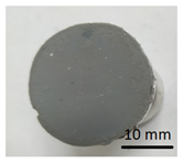
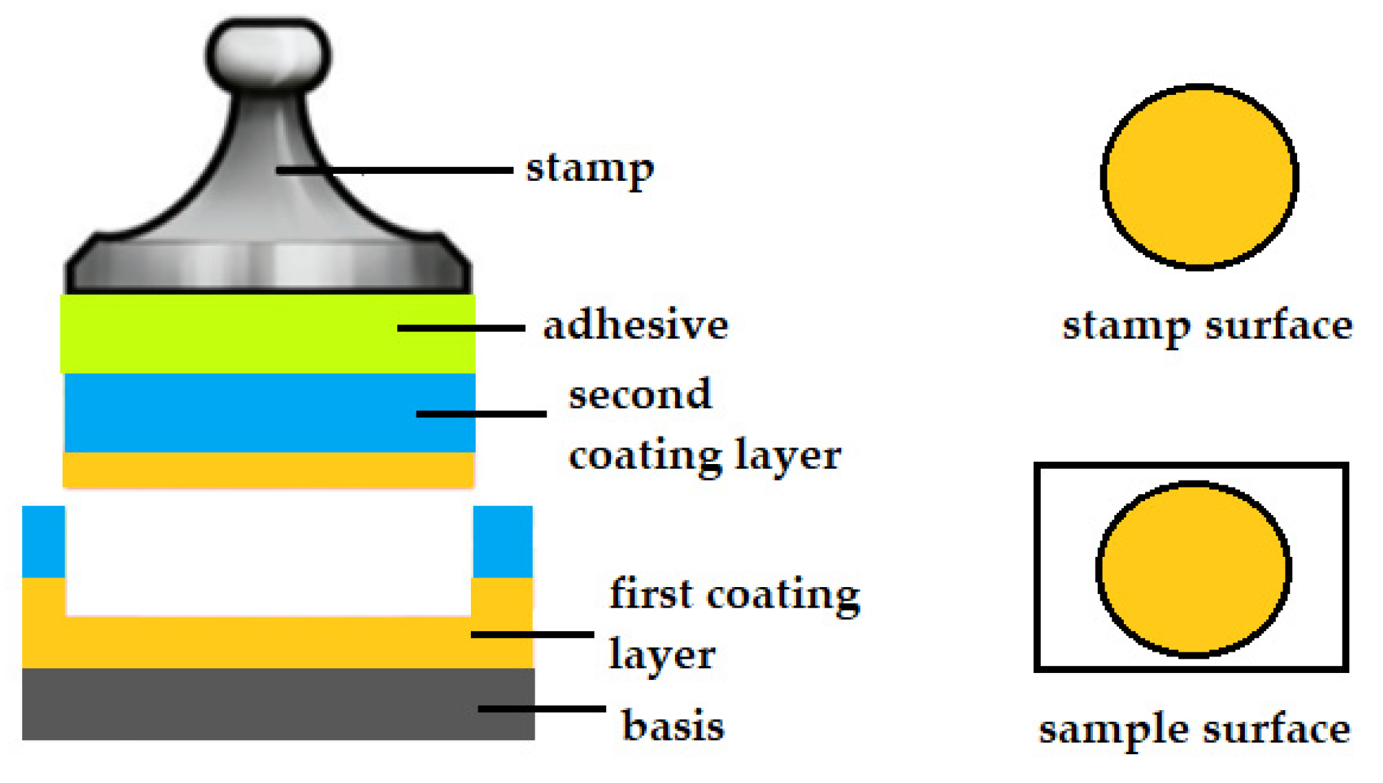
By analyzing the surface of the specimens after detachment, three types of cracking due to the applied force can be observed. The first type is a cohesive fracture. Cohesion results from intermolecular forces in the material being torn or crushed. If the fracture occurs inside the applied coating, it is called cohesive fracture. In the case of cohesive fracture, the same material is present on both the surface of the specimen and the surface of the stamp. Both these surfaces will be covered with the same coating material [
8,
9]. A schematic of cohesive cracking is shown in
Figure 1.
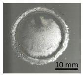
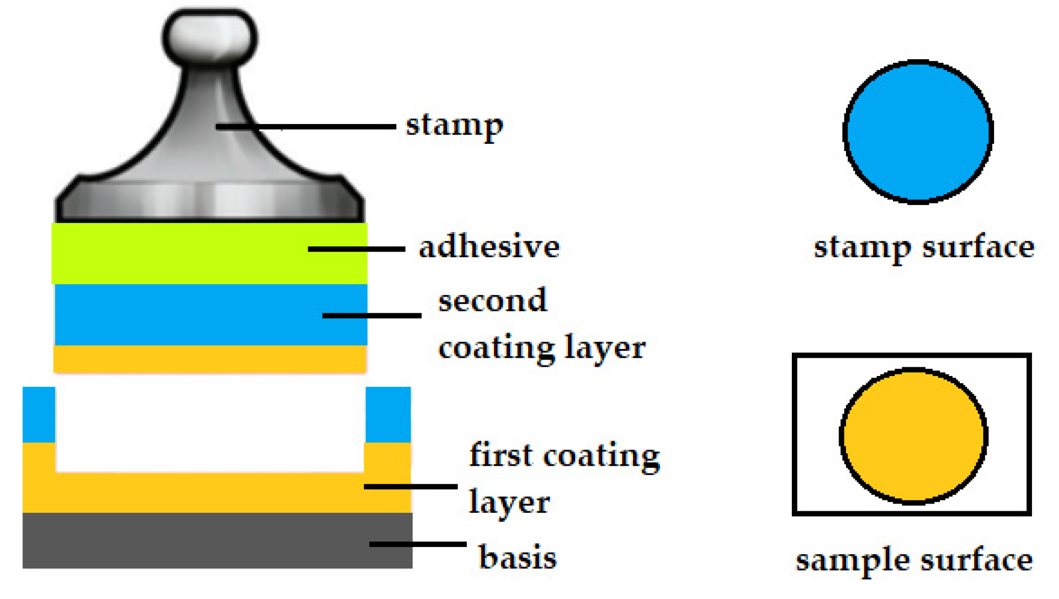
The second type of specimen rupture is an adhesive fracture. Adhesion is the interaction between molecules that are in the surface layers of two bodies adjacent to each other. Adhesion rupture indicates a low bonding ability between the surfaces of two materials. An adhesive fracture occurs between two layers (i.e. between the base and the applied coating or between the first and second coatings). In the case of an adhesive fracture, there will be a different material on the surface of the stamp than on the surface of the sample. The coating layer will be on the surface of the stamp and the second coating layer will be on the surface of the specimen or the surface of the specimen will remain uncoated [
10,
11]. The example of an adhesive fracture is shown in
Figure 2.
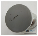
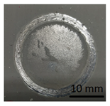
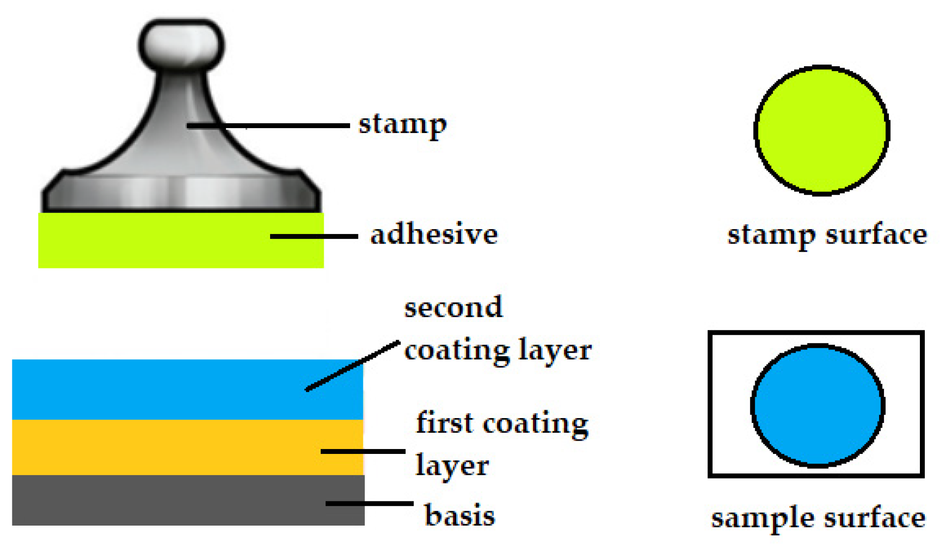
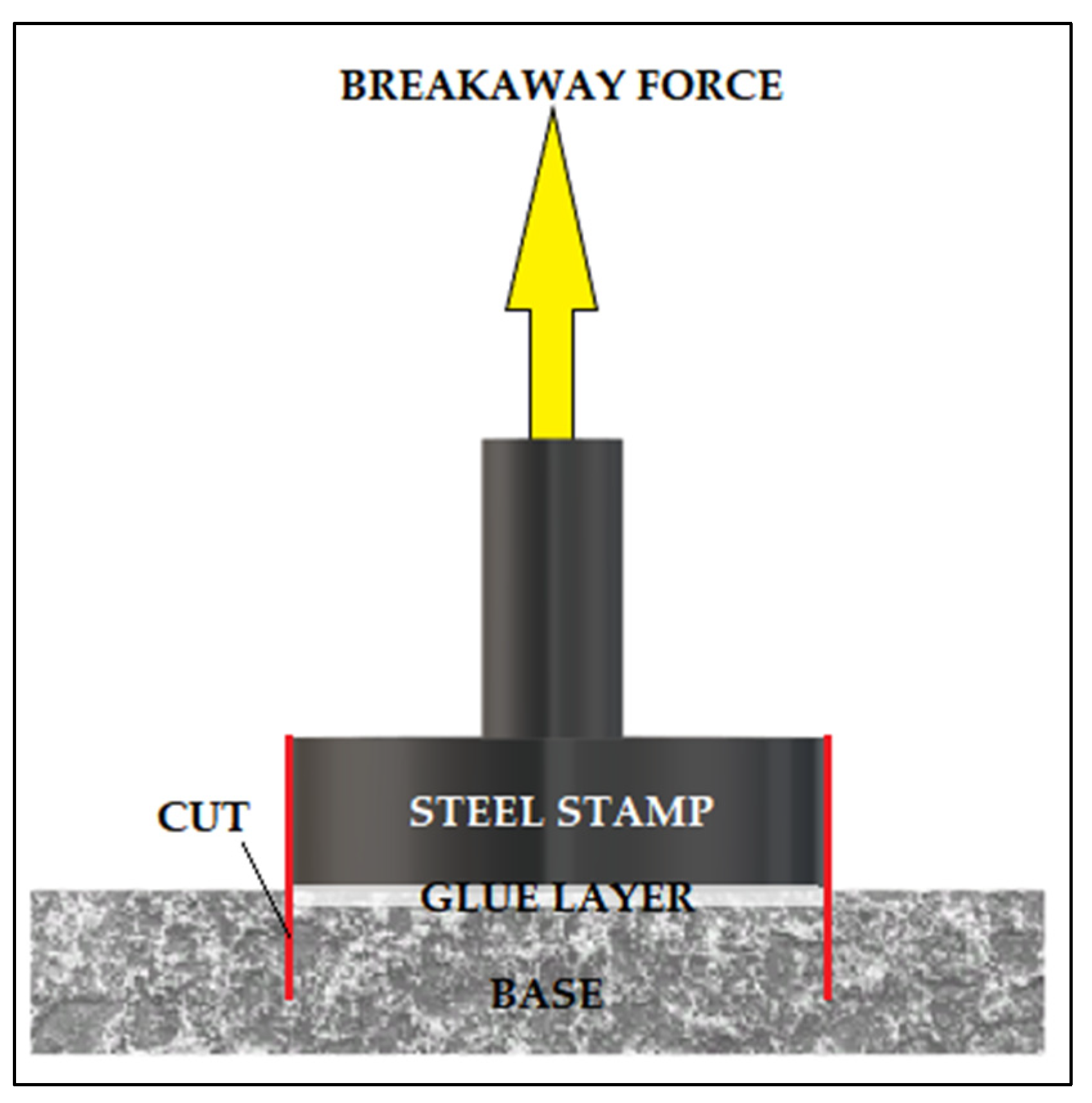
During the adhesion test, the adhesive layer may be torn internally by the application of force or the adhesive may separate completely from the coating. For the test to be considered valid, the coating must cover at least half of the surface of the stamps. If the surface of the test stamp is not coated at all, or is coated but less than 50%, the test is faulty [
10,
12]. A schematic of the separation of the adhesive from the coating is shown in
Figure 3.
Geopolymers are inorganic materials whose development has been very dynamic in recent years. Geopolymer materials can be synthesized at elevated temperature or at ambient temperature by alkaline activation of industrial wastes (fly ash, slag) or materials of geological origin (metakaolin, volcanic tuff) [
13]. Worldwide, access to starting materials (raw materials) is very common, and the demand for such materials also seems to be growing, hence their wide potential application and attractiveness. The production of geopolymers is very economical and also safe for humans and the environment. These materials are also suitable for immobilization of hazardous waste (radioactive waste, asbestos) or toxic waste (mercury, lead, arsenic) [
14,
15,
16].
Geopolymer materials are a group of modern construction materials that show a range of properties that allow them to replace common engineering materials such as traditional concretes and building composites [
17,
18]. This group of binders is characterized by such properties as high compressive strength [
19,
20,
21,
22,
23,
24,
25], resistance to acids, chlorides and sulfates [
26,
27], thermal resistance (up to about 800 °C) [
28] or good frost resistance [
29,
30], among others. Moreover, there is no corrosion of steel reinforcement in geopolymers and the material shows good adhesion properties with steel [
31].
Geopolymers appear to be a promising material for making them into protective coatings on various types of surfaces (including metals) due to their excellent mechanical, chemical and thermal properties. Geopolymer mortar has the right consistency for various application methods. It can be applied by trowel or paint roller. After application, it is left for 4 h. After drying, the surface strength of the grout is over 2 MPa, which is comparable to commonly used epoxy resins. The action of a chemically aggressive environment causes weight loss of Portland cement based concretes. Using a 10% aqueous solution of organic and inorganic acids, material degradation can be observed. Uncoated concrete can lose up to 70% of its basic mass when exposed to inorganic acids such as hydrochloric or nitric acid. The degradation is mainly related to the breakdown of the C-S-H phase and the formation of soluble calcium salts. Concrete coated with geopolymer coating, on the other hand, shows much better resistance in corrosive environments. The weight loss is estimated to be about 2% [
32]. These coatings are attracting more and more attention due to the lack of UV degradation problem or lack of susceptibility to fire. Attempts have already been made to produce such coating on metal components [
33]. Temuujin et al. fabricated geopolymer coatings on steel by focusing on the effect of Si:Al ratio on the adhesion strength of the applied coating to the substrate. They investigated both coatings produced from metakaolin-based geopolymers and also fly ash-based geopolymers. In both cases they found that the adhesion strength of the coating to steel depended on its chemical composition, and the highest adhesion strength was observed for compositions containing high amounts of silica. The effect of surface preparation on the adhesion of the coating was also observed. The coatings adhered better to rough surfaces than to a polished steel surface [
34,
35].
Deshmukh produced fly ash-based geopolymer coatings on steel using NaOH as an activator. The coatings with the highest sodium silicate content obtained the best adhesion to steel. Deshmukh studied the thermal stability and corrosion resistance of the produced geopolymer coatings. The coatings showed thermal stability up to about 500 °C; however, it was noted with increasing temperature the coatings gradually darkened. Beyond 500 °C the coatings were not stable and started to fall off from the coated steel. Electrochemical measurements showed a strong corrosion resistance of the coated material [
33]. Khan also produced geopolymer coatings on steel using fly ash as a precursor but they did not contain sodium silicate in their composition. Again, the coatings adhered well to the steel and exhibited thermal stability. Thus, it can be concluded that geopolymer coatings are an interesting alternative, and the results obtained confirm their beneficial effect on improving corrosion resistance and thermal resistance [
36].
This paper presents the results of testing the strength of adhesion of geopolymers applied to steel, conventional concrete and geopolymer. Additionally, the results of testing the adhesion of varnish layers to steel are presented, and the effect of ceramic additives introduced to varnishes as corrosion inhibitors (influence on the adhesion of layers) is evaluated. As stated in the introduction, the adhesion of protective coatings is of crucial importance for, among others, proper operation and protection of a material against corrosion. Therefore, the best possible materials and coating application methods should be developed. Geopolymers are relatively new materials that can be used as protective coatings. However, this requires further development and research in this area. There are already known cases of their use in industry, but not on a mass production scale.
2. Materials and Methods
Geopolymer were made based on fly ash, which came from the Heat Power Plant (Skawina, Poland) and river sand (Świętochłowice, Poland). Lach et al., in their works, also investigated the same type of fly ash [
7].
Table 1 shows the oxide composition of the ash determined using the XRF method.
The alkaline activator was a solution of 14 M sodium hydroxide and R-145 sodium water glass with a molar modulus of 2.5 and a density of about 1.45 g/cm3. An aqueous solution of sodium hydroxide of a given concentration was mixed with water glass at a ratio of 1:2.5 by weight. The solution was prepared according to the scheme: Technical hydroxide flakes were solubilized in water, and then an aqueous solution of sodium silicate was added. The components were mixed and allowed to reach a constant concentrate.
The same amount of sand and fly ash (1:1 weight ratio) was used to make each sample. The hydraulic additives used in this study were additionally building gypsum and Portland cement CEM 52.5. The solid components fly ash and sand were mixed dry until a homogeneous mixture was obtained, then the alkali solution was added and mixed thoroughly. The mixing was carried out in a laboratory mixer, for about 15 min.
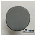
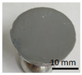
2.1. Geopolymer Layers on Steel, Concrete and Geopolymer Bases
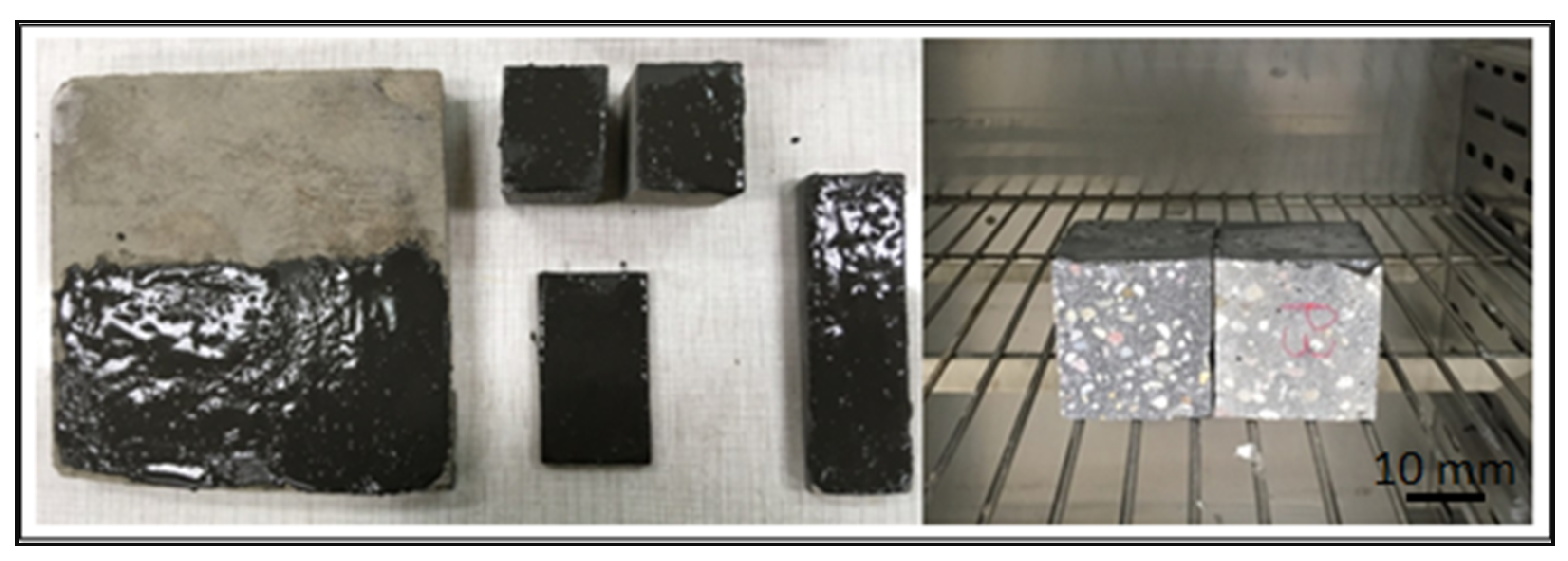
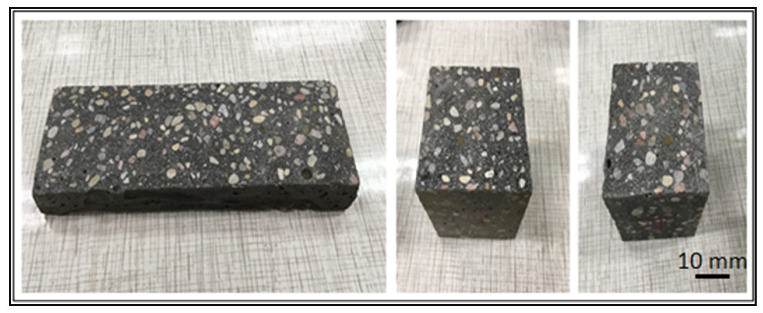
The prepared geopolymer masses were applied to different types of substrates: concrete, geopolymer and steel. An example of the appearance of the samples and how they were made is shown in the figures below (
Figure 4 and
Figure 5). The layers of geopolymer were applied manually with a special applicator. The thickness of these layers was 2 mm.
After applying the geopolymer layer, the samples were placed in an oven and cured at 75 °C for 24 h (
Figure 5).
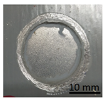
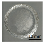
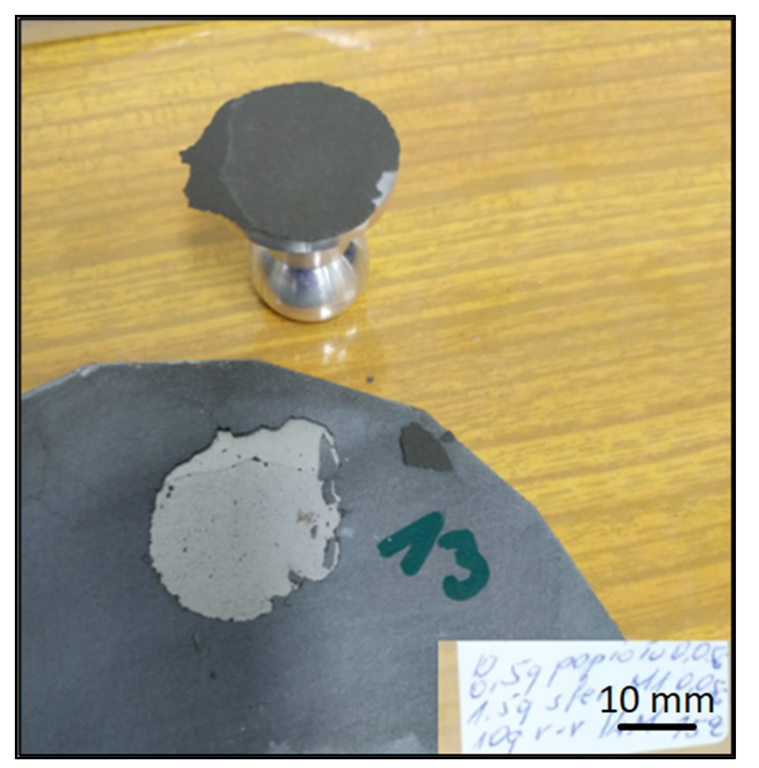
In preparation for testing the geopolymer coatings protecting the steel, DC01 steel specimens of dimensions 100 mm × 150 mm × 0.8 mm were prepared and painted on one side with geopolymer under identical conditions for each batch (temperature 23 ± 2 °C and humidity 50 ± 5%). The test tiles were flat, without deformations and complied with the requirements of ISO 1514. Before testing, the samples were conditioned for at least 16 h under identical conditions (temperature of 23 ± 2 °C and humidity of 50 ± 5%). An example of the specimen appearance (after the test) is shown in
Figure 6.
2.2. Tests of Varnish Layers with the Addition of Ceramics on Steel
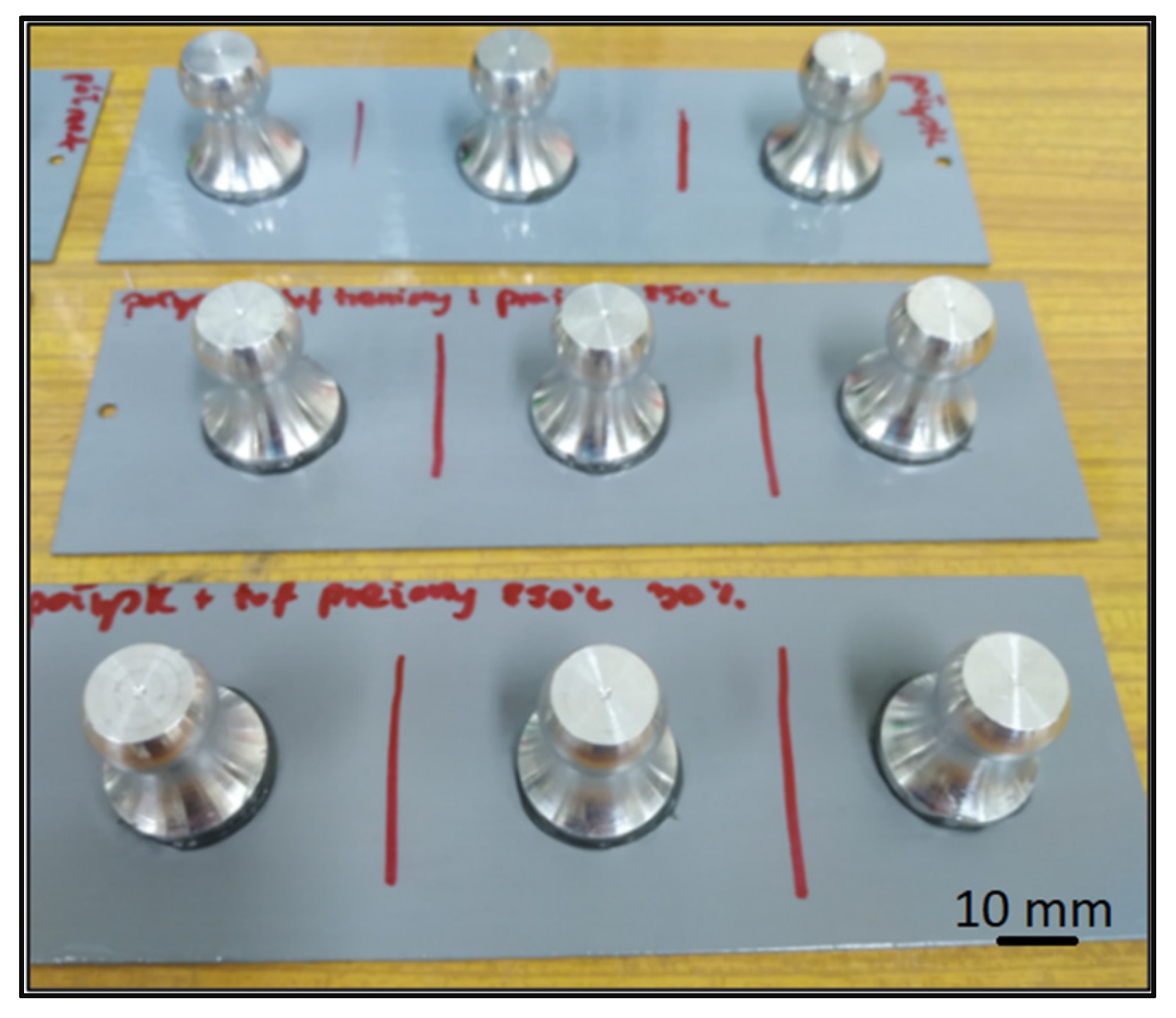
The same type of coating was used for the six coats, which was a two-component acrylic lacquer-semi-matte and gloss. Additionally, volcanic tuff was introduced to four of the coatings. Volcanic tuff was introduced to evaluate the effect of ceramic particles on the adhesion of the varnish layers. This material was chosen because of its proven corrosion inhibiting effect. The volcanic tuff used came from the Kowalska Góra field (Poland) and its main composition is sanidine and silica. Three samples were made for each type of coating. The samples after sticking the measuring stamps are shown in
Figure 7.
Table 2 gives the characteristics of the coatings that were tested in the pull-off test.
Table 3 shows the characteristics of the geopolymer coated samples tested by the pull-off method.
2.3. Test Method
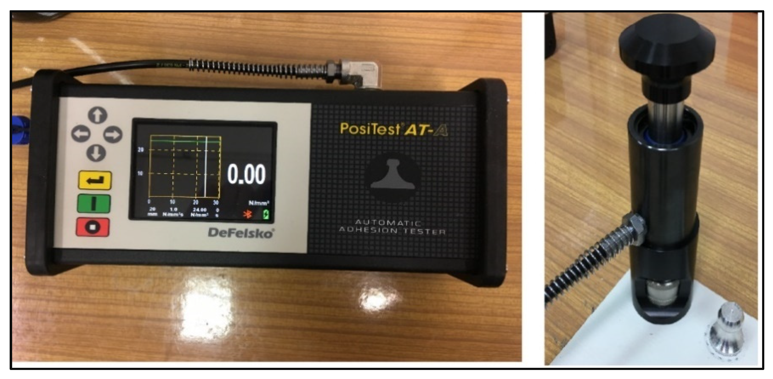
The device used to perform the pull-off measurements was the DeFelsko’s PosiTest AT-A pull-off device (ATA20, DeFelsko Corporation, Ogdensburg, New York, USA). The AT-A model is an automatic meter that uses a hydraulic cylinder. It measures the force or stress required to peel a specific area of the coating from the substrate using hydraulic pressure. The value of the force or stress, depending on which option is selected in the settings, is displayed on the device and describes the adhesion of the coating to the substrate. The instrument gives a choice of units such as psi, Niutons, MPa or N/mm2. When making measurements for this thesis the unit [N/mm
2] was chosen and the results will be reported in this unit. According to ISO 4624, ASTM D4541 and D7234, the PosiTest device evaluates the peel strength of a coating by determining the highest tensile force it can withstand before rupture. The PosiTest AT-A device is shown in
Figure 8 and the pull-off test scheme is shown in
Figure 9.
3. Results
The following are the results of testing the adhesion of geopolymer and varnish layers to various substrates. The results should be evaluated both by considering the numerical force values measured with the pull-off tester and by visually evaluating the peeled off coatings (surfaces).
3.1. Varnish Coatings
After the pull-off test, the surface of the samples and the surface of the stamps were analyzed to determine the type of cracks present.
Table 4 shows the appearance of the stamps and the surface of the varnished specimens after the pull-off test.
For the three samples made for the semi-matt coating without additives, the fractures were both adhesive and cohesive in character. For sample number C.1, adhesive fracture between the coating and the substrate occurred on more than half of the sample surface. For sample number C.2, however, adhesive rupture occurred on an area of less than 50% of its surface. Sample number C.3 had approximately 90% adhesion detachment. The remaining area for each of these three samples was cohesive rupture within the coating. Such a varied appearance of the surface of the samples after the test may be indicative of a non-homogeneous preparation of the substrate before coating. The substrate may have had different roughness in the areas concerned, which affected the adhesion properties of the coating.
Table 5 shows the stamp and surface of the samples coated with semi-matt varnish after the pull-off test. In this case, etched and heated at 850 °C, the tuff was added to the varnish before it was applied to the substrate.
For specimens C.4, C.5 and C.6 coated with a semi-matt coating with an addition of tuff etched and heated at 850 °C, the fracture was approximately 85% adhesive between the coating and the substrate and approximately 15% cohesive within the coating. For these samples, cohesive fracture is observed mainly at the edges of the area to which the stamp was adhered.
Table 6 shows the appearance of the stamps and the substrate after the pull-off test, for layers of varnish, with the addition of heated tuff at 850 °C.
For specimens C.7, C.8 and C.9 with a varnish coating containing heated tuff at 850 °C, only cohesive cracks were observed within the coating. However, the coating layer that remained intact on the surface side was very thin. The translucent metal substrate DC01 can be observed in the figures.
Table 7 shows the stamps and surfaces of the gloss-coated specimens after the pull-off test.
Samples numbered C.10, C.11 and C.12 showed mainly adhesive detachment between the substrate and the applied coating.
Table 8 shows the appearance of the stamps and substrate after the pull-off test, for varnish layers (gloss), with the addition of etched and heated at 850 °C tuff.
The samples coated with gloss varnish with etched and heated tuff (C.13, C.14 and C.15) detached both adhesively and cohesively. Additionally, in their case, areas were observed where the coating could not be detached due to insufficient adhesive strength. The problem with partial non-adhesion of the adhesive to the coating may have been caused by irregular roughness of the coating or insufficient cleaning of the coating in some areas. Sample number C.15 had about 70% adhesive breakage, while for samples C.13 and C.14 the proportion of cohesive breakage area was much higher than adhesive breakage.
Table 9 shows the appearance of the stamps and the substrate after the pull-off test, for layers of varnish, with the addition of heated tuff at 850 °C.
The samples coated with a glossy varnish with added tuff heated at 850 °C detached adhesively.
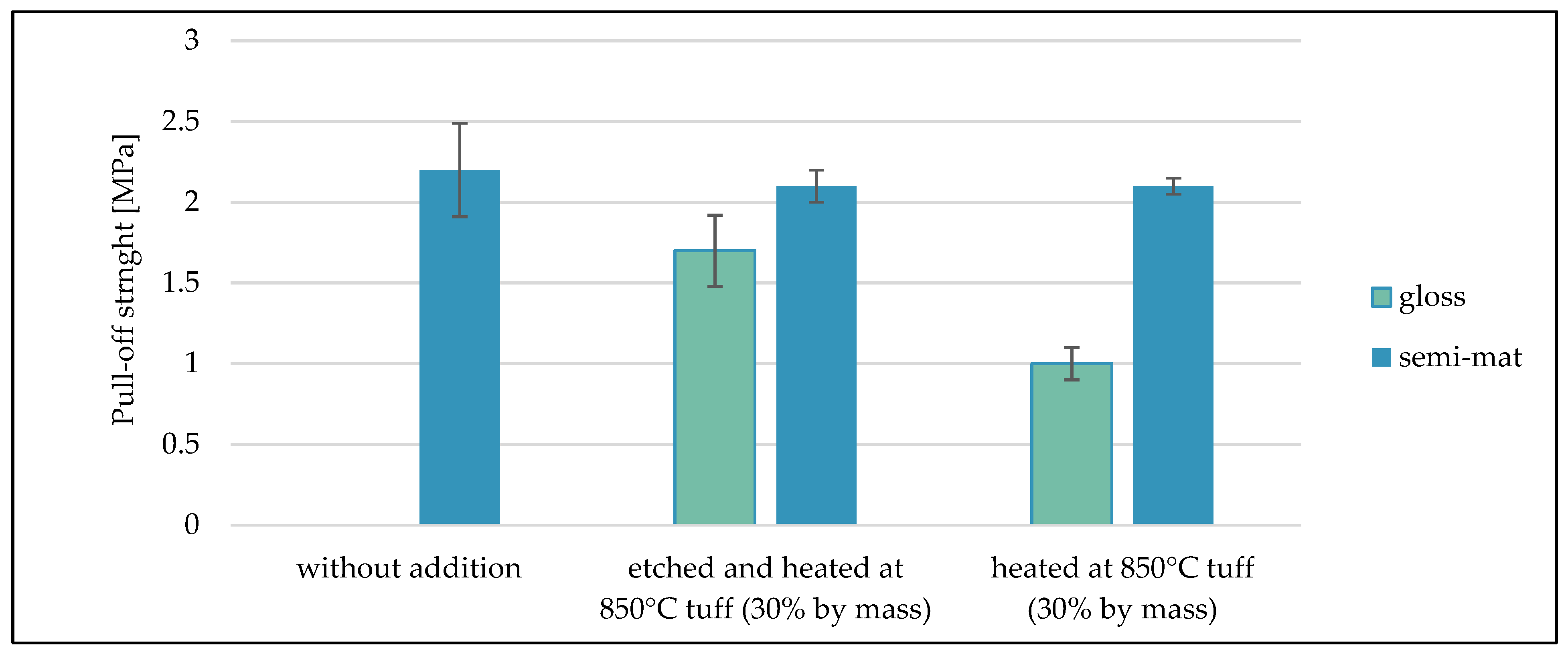
Figure 10 shows the average results from the pull-off test carried out for the different variants of coatings varnished on the DC01 steel base.
For samples (C.10, C.11, C.12) coated with glossy varnish without any additives, the measurement failed because the obtained value of breaking stress was too low for the device to register the measurement. The highest values of breaking stress were obtained for samples coated with semi-matt varnish without tuff addition. The average pull-off stress value was in the range of 2.2 MPa. Similar values of rupture stresses were achieved by coatings made of semi-matt varnishes with tuff addition. These values were about 2.1 MPa. The lowest average pull-off strength value was achieved by coatings made of glossy varnish with tuff addition (about 1.0 MPa).
3.2. Geopolymer Coatings
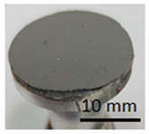
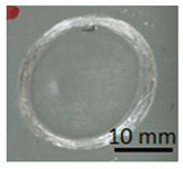
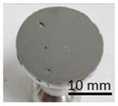
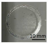
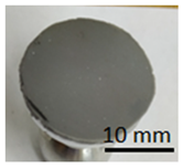
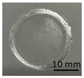
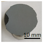
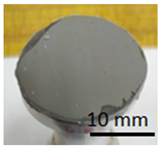
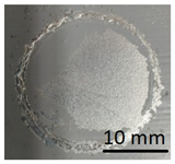
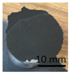
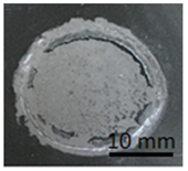
The samples in
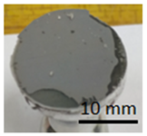
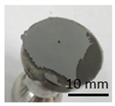
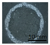
Table 10 below show the geopolymer coating on DC01 steel. Samples G.1 and G.2 were not cut with the cutting instrument before detachment. It can be seen that the coating was also detached outside the cutting area, particularly in the case of sample G.1. Adhesion damage occurred in all examples shown in the figures.
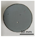
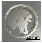
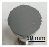
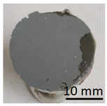
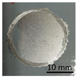
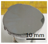
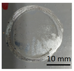
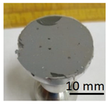
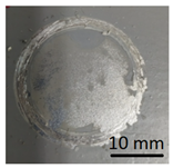
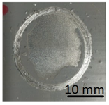
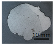
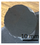
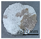
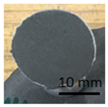
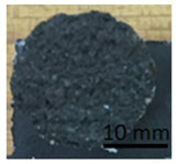
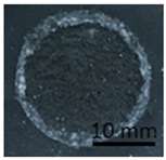
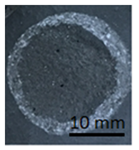
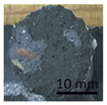
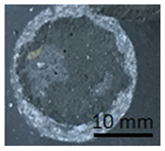
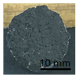
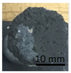
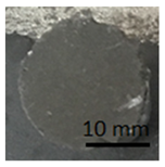
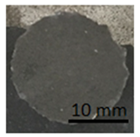
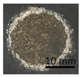
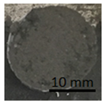
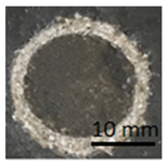
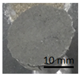
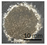
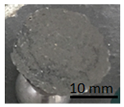
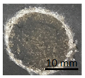
Table 11 shows samples with a geopolymer layer on a geopolymer concrete substrate. The geopolymer material is characterized by a rather high porosity. Due to the fact that the coating was applied by hand, it was impossible to obtain a perfectly smooth surface. All samples were cut out with a cutting tool. The applied coating has "peeled off". The same coating is present on both the stamp surface and the base surface. In addition, in samples G.7 and G.9, a section of the substrate was also torn out (visible as a lighter area on the stamp surface and on the base). This damage can be described as cohesive damage, as the pull-out occurred within the coating and substrate, rather than at the interface between the material layers.
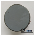
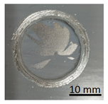
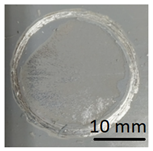
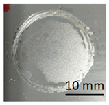
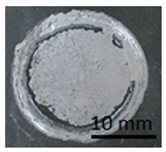
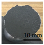
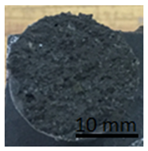
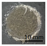
Table 12 shows samples with a geopolymer layer on the surface from a concrete slab. In each case shown in
Table 12, it can be seen that the tested layer remained on the punch and on the concrete surface. The character of the rupture can be described as adhesive and cohesive failure.
Figure 11 shows the average results of the pull-off test carried out for geopolymer coatings on different types of substrate.
The average breaking strength of the geopolymer coating on the geopolymer concrete substrate was about 6 MPa, while on the concrete slab substrate it was about 4 MPa. The pull-off strength of the geopolymer coating applied to the steel slab was not successfully tested. The reason for this is that the coating-substrate bond is too weak. As a result, the measuring equipment did not record any stress value.


 ,
, 


