Article

Optimizing Design Parameters of PLA 3D-Printed Scaffolds for Bone Defect Repair

by
Alexandrine Dussault
1,
Audrey A. Pitaru
2,
Michael H. Weber
3,
Lisbet Haglund
3,4,
Derek H. Rosenzweig
3,5 and
Isabelle Villemure
6,*
1
Polytechnique Montréal, Montreal, QC H3C 3A7, Canada
2
Experimental Surgery, McGill University, Montreal, QC H3A 0G4, Canada
3
Department of Surgery, Montreal General Hospital, McGill University, Montreal, QC H3G 1A4, Canada
4
Shriners Hospital for Children, Montreal, QC H4A 0A9, Canada
5
Injury Repair Recovery Program (IRR), Research Institute of McGill University Health Centre, Montreal, QC H3A 0G4, Canada
6
Polytechnique Montréal, CHU Sainte-Justine, Montréal, QC H3T 1J4, Canada
*
Author to whom correspondence should be addressed.
Surgeries 2022, 3(3), 162-174; https://doi.org/10.3390/surgeries3030018
Submission received: 7 June 2022 / Revised: 21 June 2022 / Accepted: 22 June 2022 / Published: 28 June 2022
(This article belongs to the Special Issue 3D Printing in Surgical Strategies)

Abstract

:
Current materials used to fill bone defects (ceramics, cement) either lack strength or do not induce bone repair. The use of biodegradable polymers such as PLA may promote patient healing by stimulating the production of new bone in parallel with a controlled degradation of the scaffold. This project aims to determine the design parameters maximising scaffold mechanical performance in such materials. Starting from a base cylindrical model of 10 mm height and of outer and inner diameters of 10 and 4 mm, respectively, 27 scaffolds were designed. Three design parameters were investigated: pore distribution (crosswise, lengthwise, and eccentric), pore shape (triangular, circular, and square), and pore size (surface area of 0.25 mm2, 0.5625 mm2, and 1 mm2). Using the finite element approach, a compressive displacement (0.05 mm/s up to 15% strain) was simulated on the models and the resulting scaffold stiffnesses (N/mm2) were compared. The models presenting good mechanical behaviors were further printed along two orientations: 0° (cylinder sitting on its base) and 90° (cylinder laying on its side). A total of n = 5 specimens were printed with PLA for each of the retained models and experimentally tested using a mechanical testing machine with the same compression parameters. Rigidity and yield strength were evaluated from the experimental curves. Both numerically and experimentally, the highest rigidity was found in the model with circular pore shape, crosswise pore distribution, small pore size (surface area of 0.25 mm2), and a 90° printing orientation. Its average rigidity reached 961 ± 32 MPa from the mechanical testing and 797 MPa from the simulation, with a yield strength of 42 ± 1.5 MPa. The same model with a printing orientation of 0° resulted in an average rigidity of 515 ± 7 MPa with a yield strength of 32 ± 1.6 MPa. Printing orientation and pore size were found to be the most influential design parameters on rigidity. The developed design methodology should accelerate the identification of effective scaffolds for future in vitro and in vivo studies.

1. Introduction

Several conditions such as infection, trauma, or cancer can result in large surgical bone defects that present many challenges for reconstructive orthopedic surgery [1]. Current treatments include autologous and allogenic bone grafting as well as acrylic and ceramic bone cements [1,2]. There are several drawbacks to these types of treatments. Autografts result in donor site morbidity, and present an availability problem [3,4]. Acrylic bone cements provide mechanical support without regenerative properties, while ceramic cements can promote bone repair yet lack mechanical strength [1,5]. Therefore, there is an unmet clinical need for better bone substitutes, which can provide both mechanical support and tissue regenerative properties. In this regard, research has been focusing on scaffolds made of polymers and composite materials [3]. Tissue engineering (TE) is a growing area of interest in bone repair, whereby scaffolds are combined with cells and biologics to be used as temporary implants promoting bone regeneration and tissue ingrowth [6,7]. TE aims to restore, maintain, or improve tissue functionality [2], with the long-term goal of replacing damaged tissues and organs [8]. It is presented as an alternative approach to eliminate the drawbacks of autologous and allogeneic bone grafts [3,9].
Several types of scaffolds have been developed over the years for use in bone repair. Seeing as bone tissue is a heterogenous material composed of hydroxyapatite mineral [10] and organic components such as collagen, scaffolds should be designed as a combination of materials to achieve structural biomimicry [11]. Indeed, combining materials, such as PLA (polylactic acid) and cHA (carbonatite hydroxyapatite) to produce composite or hybrid scaffolds has been proven to improve bioactivity [5,11]. The PLA/HA combination attracts many researchers since it is more similar to natural bone tissue (in structure and composition) than ceramic or polymer materials alone [12]. Composite scaffolds made of TCL (terephthaloyl chloride) combined with magnesium can promote bone healing [9], and composite scaffolds made of PCL (polycaprolactone) combined with a hydrogel infused with small molecules (resveratrol and strontium ranelate) can significantly promote bone formation in critical-sized mandibular bone defects [13]. Furthermore, several studies have pointed to the osteogenic impact of composite polymeric scaffolds combined with nano-hydroxyapatite [14]. Metal-based scaffolds have also provided great results. Several clinical studies have shown that porous titanium scaffolds provided satisfactory results in large bone defects [7].
Additive manufacturing in the form of 3D printing has rapidly gained traction for bone repair applications. In fact, a FDA-approved, 3D-printed scaffold for bone repair is available commercially/clinically for spine fusions [15]. Major advantages of using 3D printing for scaffolds are that an enormous range of geometries, pore sizes, and materials can be used to control mechanics, degradation rates, and biological impact of the scaffold [16]. Many polymeric materials present great rigidities and are bioresorbable, meaning that following implantation and bone regeneration support, they will be gradually replaced by new tissue [17]. For example, PLA is a commonly used material for bone tissue replacement, mainly due to its high mechanical properties [18,19] and its great biocompatibility and biodegradability [1,2,18,19]. It has been proven to be effective for trabecular bone replacement [2,18]. It is also an inexpensive and commonly available material. In line with what other groups have found, we have shown that low-cost 3D printers can generate scaffolds of various pore sizes to control stem cell differentiation [1,16,20,21] and that composite scaffolds containing beta-tricalcium phosphate or hydroxyapatite can also drive stem cell differentiation and promote bone repair in animal models [22,23,24].
In terms of scaffold design, several parameters are crucial, namely porosity, pore size, and pore configuration. Porosity allows cell migration and improves surface area, promoting osteogenesis [7]. For example, porosities higher than 50% promote vascularization [25]. However, high porosity can hardly respect the need for the high mechanical strength required for bone usage, suggesting that a compromise must be made among porosity, strength, and osseointegration [7]. Indeed, Zhang et al. showed that scaffold rigidity decreases linearly with increasing scaffold porosity [26]. Previous studies have also shown that pore size and pore density have an impact on cellular growth and attachment [27,28], indicating that scaffolds must be engineered in a way which favors the type of cells and tissues they intend to supplant [11]. Here, we set out to examine various configurations of pore geometry, pore size, and pore configuration to determine the combination providing the highest mechanical properties, while keeping in mind that there is a need for adequate cell proliferation and osteogenesis. We also compared two printing orientations (fiber alignment) and evaluated their impact on scaffold rigidity. This parameter was also tested by Zhang et al., who found that when the filaments are aligned with the direction of the compressive loading, they can better sustain the mechanical load than when they are perpendicular [26]. The design parameters were chosen following a literature review focusing on scaffold design on rigidity and cell differentiation. In that review, we found a recurrence of square pore shapes of size ranging from 0.4 cm to 1.0 cm, with a porosity varying from 20% to 84% [1,20,25,26,29,30,31,32]. A bone graft substitute in combination with drug carriers can locally deliver anti-cancer therapeutics [33], which could prevent cancer recurrence. Therefore, our base scaffold model is a hollow-centered cylinder, allowing the addition of a drug-infused material.

2. Materials and Methods
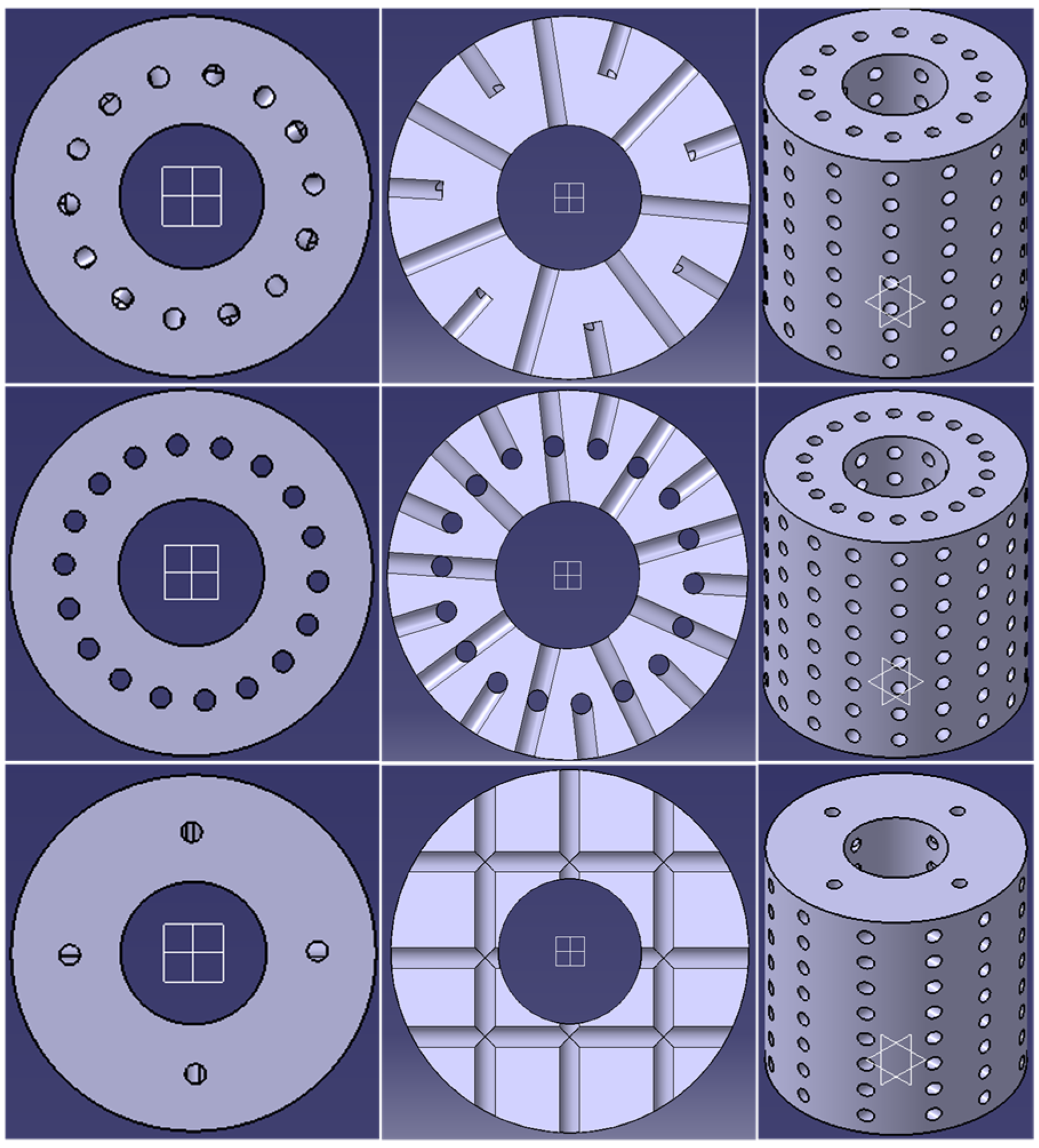
The methodology includes five main steps: (1) CAD design of multiple scaffold models; (2) finite element simulations of compressive testing on the models, which allowed discriminating models to print; (3) 3D printing of retained models; (4) experimental compression testing of printed models; (5) data analysis to retrieve scaffold rigidity and determine the “best model” for bone replacement.

2.1. CAD Design

A total of 27 scaffolds were designed starting from a cylindrical base model of 10 mm in height, with outer and inner diameters of 10 mm and 4 mm, respectively. Three design parameters were investigated: pore distribution (crosswise, lengthwise, and eccentric), pore shape (circular, square, and triangular), and pore size (equivalent surface areas of 0.25, 0.56, and 1 mm2). The pores’ diameters/sizes were adjusted so that each shape corresponded to the same surface area. Figure 1 shows multiple views of the three different pore distributions for a scaffold with large circular pores. The design was made using CATIA V5 (Dassault Systèmes, SolidWorks Corporation; Waltham, MA, USA) while considering the resolution of the FDM printer used (Monoprice MP Select Mini v2 (Monoprice Inc; Brea, CA, USA)). Hence, the space between pores and between the outer edge of a pore and the base of the scaffold was set to a minimum of 0.5 mm to ensure proper printing. The CAD models were converted to STL files and sliced using an Ultimaker Cura 4.6.1 (Ultimaker B.V.; Utrecht, The Netherlands) to prepare the G-code necessary for printing.
Table 1 details the resulting porosity of each scaffold model. The porosity was calculated following Equation (1). To do so, we used the Measuring Inertia command in CATIA to get the scaffold’s volume and the volume of the cylinder without any pores.
Porosity   ( % ) = ( Volume   of   the   cylinder     Volume   of   the   scaffold )   ( c m 3 ) Volume   of   the   scaffold   ( c m 3 ) × 100   %

2.2. Finite Element Simulations of Compression Testing

Simulated mechanical testing of a compressive load was performed on each model using a finite element analysis (FEA) software, ANSYS Workbench 2019 R2 (ANSYS; Canonsburg, PA, USA). To do so, adequate meshing of the 3D models was required. However, not all pore distributions with a triangular pore shape could be meshed because some had sharp edges. A convergence study was done to determine the optimal meshing sizes for each scaffold size (small, medium, and large) using the square crosswise model, to give fast yet precise calculations. Scaffolds were meshed according to 4 different sections: inner/outer edge of the base, base surface area, inside the pores, and everything else. The mesh sizes were tested from coarse to fine, calculating a maximum normal stress. A mesh size was chosen when the next iteration took a significantly longer time to compute, while having little difference in resulting stress. For the simulation, the scaffold material was PLA modeled as linear elastic with a density of 1.24 g/cm3 and a material rigidity of 1000 MPa, which was established by the calibration of previously tested sample data. The resulting scaffold rigidity, which is different from material rigidity, was obtained from simulations of a compressive loading to 15% strain at a 0.05 mm/s displacement rate.

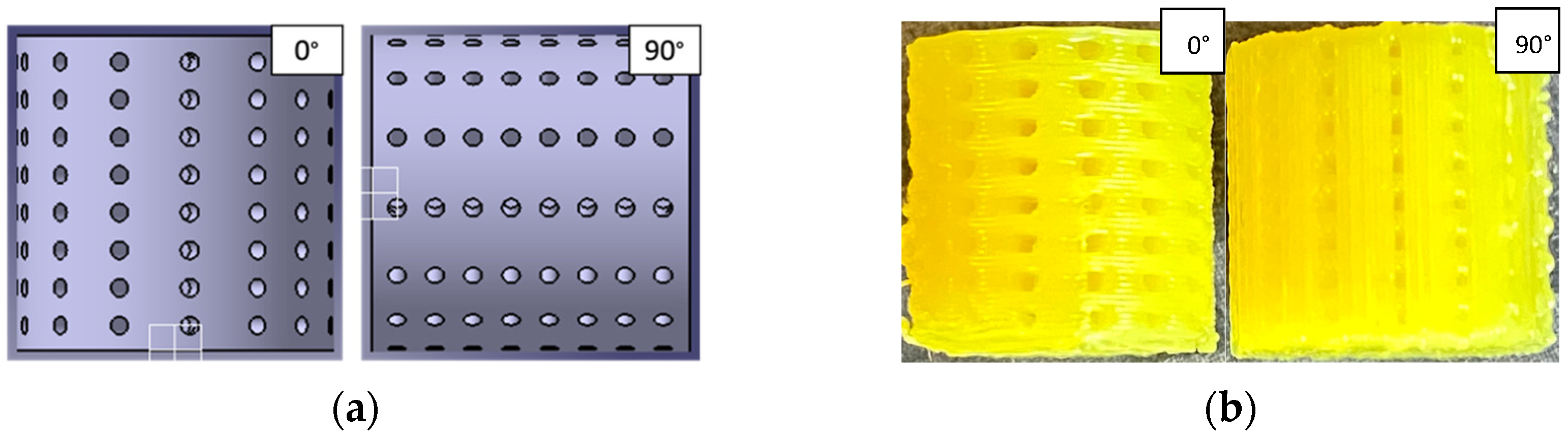
2.3. Printing and Experimental Compression Testing

As already specified, printing was carried out using the Monoprice MP Select Mini v2. Following the finite element results, the models resulting in high scaffold rigidities were 3D printed (n = 5/model) in 1.75 mm PLA (MakerGeeks; Springfield, MO, USA) along two orientations: 0° (the cylinder is sitting on its base) and 90° (the cylinder is laying on its side, flat on the print bed, with enabled support in the Cura slicer settings). Printing orientation is therefore the 4th investigated parameter. At this point, all models with a triangular pore shape were excluded because convergence studies were not conclusive. A total of 120 scaffolds were printed with a 0.3 mm nozzle diameter, 0.2 mm layer height, and 100% infill—60 specimens with a 0° orientation and 60 with a 90° orientation, each group composed of 12 different models printed 5 times. The 12 models can be separated in 2 subgroups, crosswise and lengthwise pore orientations. In each of those groups, we can find square and circular pores in 3 sizes (surface area), that is, small (0.25 mm2), medium (0.56 mm2), and large (1 mm2). The scaffolds were printed one by one on a 50 °C bed with a 210 °C printing temperature at a 15 mm/s speed. Printed scaffolds were further tested along the vertical cylinder axis on MTS Insight Electromechanical Testing Systems (MTS; 14,000 Technology Dr. Eden Prairie, MN, USA). The machine was programmed to perform the exact same test as the simulations, which was a compressive load at a displacement of 0.05 mm/s for a 15% strain.

2.4. Analysis

2.4.1. Simulations

To extract the data to obtain the scaffold rigidity of each model, the f and force (N) were respectively normalized to strain (%) and stress (MPa) with respect to their sample initial height (mm) and base area (mm2), using Equations (2) and (3):
Strain   ( % ) = Displacement   ( mm ) Initial   height   ( mm )   ×   100   %
Stress   ( MPa ) = Force   ( N ) Area   of   the   base   ( m m 2 )
The area of the base is 65.97 mm2 for each model. It corresponds to the surface area of the top view of the cylinder (resembling a donut shape) and it excludes the pores, which we considered negligible for this measure. The scaffold rigidity was then obtained from the corresponding stress-strain graph, following Equation (4):
Scaffold   rigidity   ( MPa ) = Stress ( MPa ) Strain   ( mm / mm )

2.4.2. Experimental Testing

Prior to mechanical compression testing, the initial height and diameter of each sample was first measured with a micrometer (precision of 0.05 mm) to define the exact strain, and the same process as for the simulations was done using Equations (1) and (2). Then, a stress-strain graph was produced using Microsoft Excel. A visual analysis made it possible to deduce the points associated with the beginning and the end of the slope corresponding to the elastic strain.

2.4.3. Statistical Analyses

T-tests were performed to determine the statistical significance of the mean rigidities of scaffolds for different configurations retrieved from experimental testing. Four statistical tests were carried out. For scaffolds with square pores, crosswise pore orientation was tested against lengthwise pore orientation for all pore sizes and both printing orientations (test 1). The same analysis was done for scaffolds with circular pores (test 2). Square and circular pores were tested against each other with a crosswise pore orientation, for every pore size and printing orientation (test 3). The same was done with lengthwise pore orientation (test 4).

3. Results

3.1. Results from Simulations

The following Table 2 compares the scaffold rigidities for each model using finite element simulations.
The square and circular pore shapes gave similar results for both crosswise and lengthwise configuration, with slightly higher rigidities for the circular pore shape and lengthwise pore distribution. The rigidities with the eccentric distribution were smaller than the two others, but also similar for square and circular pore shapes. The triangular pore shape gave results 19% to 23% smaller than its counterparts. Additionally, these models could not converge for four out of nine simulations. Therefore, models with a triangular pore shape and eccentric configuration were excluded for the remaining of the study. Regarding pore size, scaffolds with smaller pores—and smaller porosity, as seen in Table 1—resulted in higher rigidities than the ones with medium pores and larger pores. Table 2 indicates the simulated rigidity for each geometry, size and orientation. Triangular shaped pores could not be calculated and were hence removed from the remainder of the study.

3.2. Results from Experimental Testing

3.2.1. Printing

Figure 2 shows the two printing orientations along with two printed scaffolds.

3.2.2. Experimental Testing

We can observe in Figure 3 that the curves of models printed with a 0° orientation are similar to typical PLA stress-strain curves [34], whereas a 90° orientation is not. The 90° sample slope starts to get steeper much later than the 0° sample slope, which could be explained by faults induced by the printing orientation: the base surface is less smooth when printed sideways (90°), as we can observe on Figure 2b. Therefore, there are some physical adjustments at the interface between the compressive device and the scaffold, which may induce some surface imperfections, explaining the prominent toe region of the curve. Mean scaffold rigidities for each printed configuration are presented in Figure 4. Scaffolds printed with a 90° orientation provided much higher rigidities than the ones printed with a 0° orientation, all models combined. As expected from the simulations, scaffolds with smaller pores and smaller porosity presented higher rigidities. However, experimental testing showed that crosswise models had higher rigidities than lengthwise models, which can be confirmed with the statistical analysis. The complete experimental data can be found in Supplementary Materials.
The mean yield strength for each printed configuration is presented in Figure 5. Yield strength corresponds to the stress at which the deformation is no longer considered reversible. This stress value should never be exceeded. We can see from Figure 5 that those values are much higher for scaffolds printed with a 90° orientation, allowing for higher stresses.
Table 3 summarizes every result obtained for square and circular pore shapes, from finite element to experimental testing.

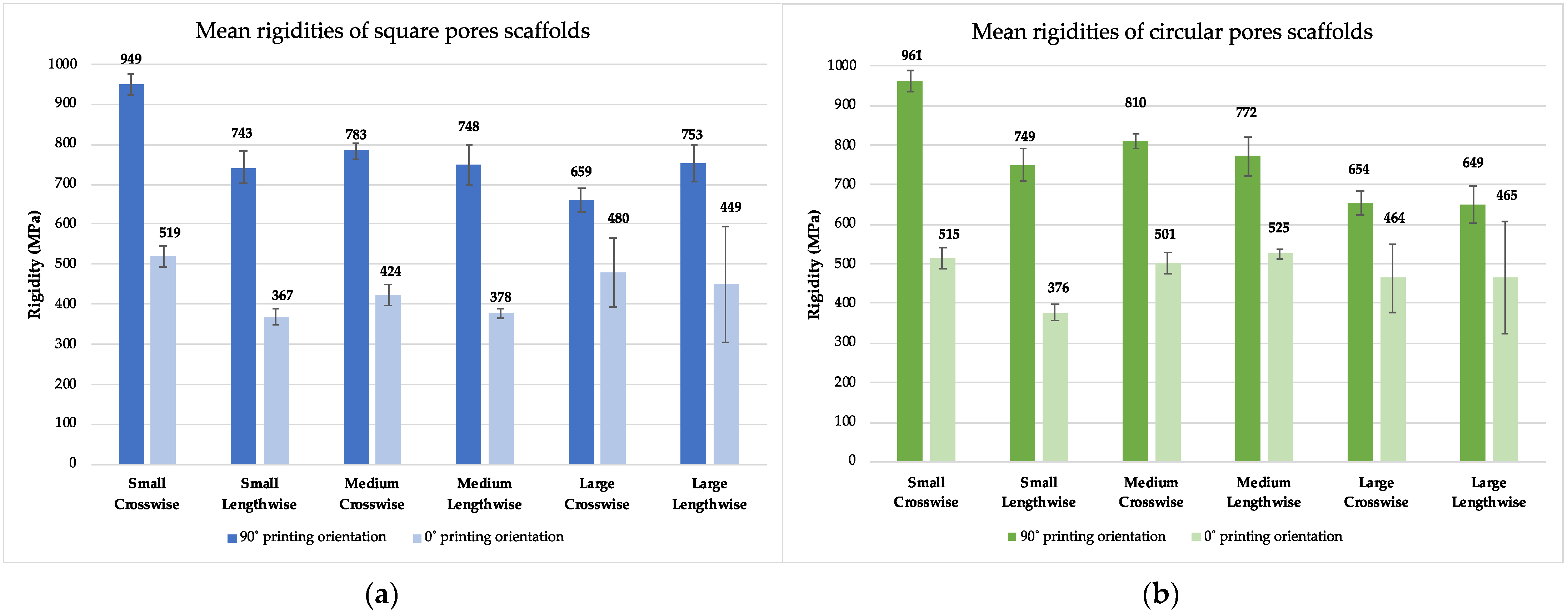
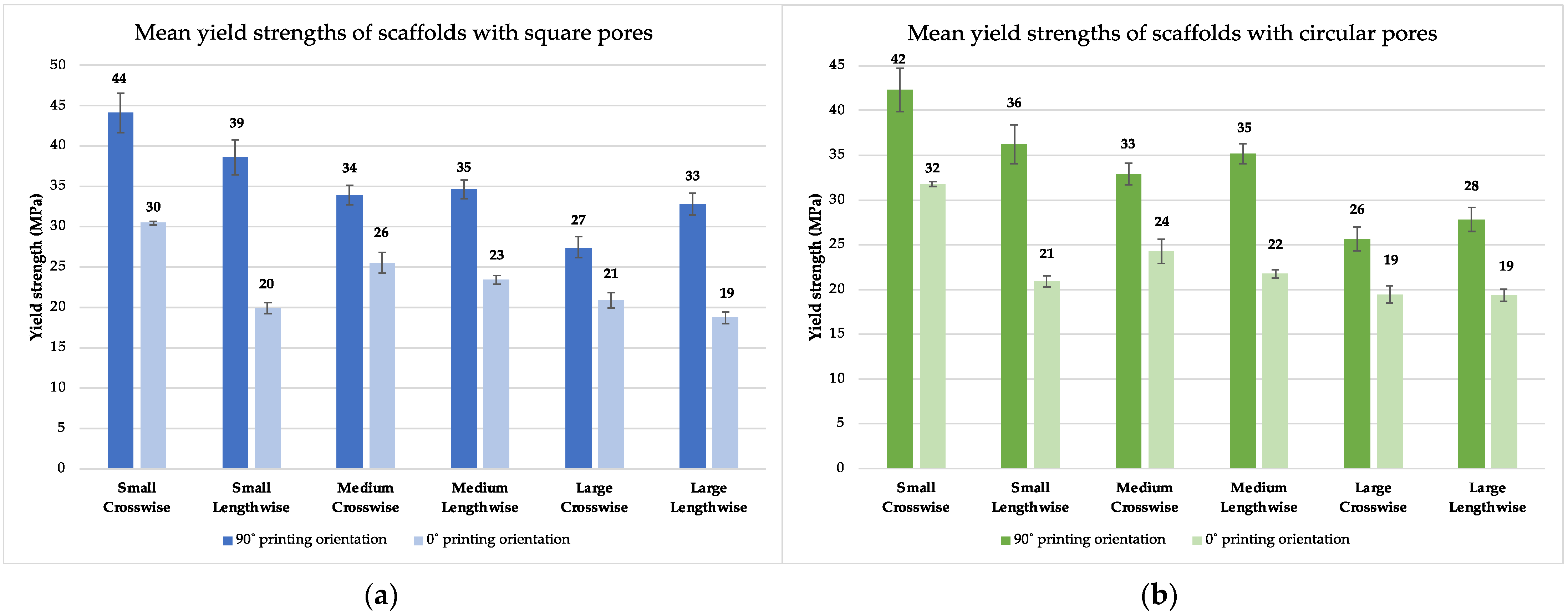
3.3. Comparative Analysis of Rigidity and Yield Strength

The complete statistical analyses can be found in Supplementary Materials. For the square pore models, we found the mean rigidities to be statistically significant (p < 0.05) between crosswise and lengthwise pore orientations for small pores (for both printing orientations), medium pores (for 0° printing orientation), and large pores (for 90° printing orientation). This means that the square pore scaffold with the highest rigidity is the one with small pores and a crosswise pore orientation. For the circular pore scaffolds, we found the mean rigidities to be statistically significant (p < 0.05) between the two pore orientations only for small pores (for both printing orientations). This means that the circular pore scaffold with the highest rigidity is the one with small pores and a crosswise pore orientation. When testing the two pore shapes against each other with a crosswise pore orientation, and then with a lengthwise pore orientation, we only found a significant (p < 0.05) difference between mean rigidities for medium scaffolds with lengthwise pore orientation for a 0° printing orientation (meaning that circular pore scaffolds have higher rigidity for this model).
Differences between mean yield strengths were significant. For the square pore shape, when comparing crosswise against lengthwise pore distribution, we found the mean yield strength to be statistically significant (p < 0.05) for all models except for medium−90° scaffolds. This means that crosswise models permit a much higher strain before plastic deformation than their lengthwise counterparts. The results are similar for scaffolds with circular pores; only the large−0° and large−90° models had yield strengths that were not statistically significant. When testing the two pore shapes against each other with a crosswise pore orientation, we found that circular-pore-shaped models exhibited higher yield strengths for medium−90° and large−0° scaffolds than models with square pores (p < 0.05). A similar situation was observed with the lengthwise pore orientation, for small−0°, medium−0°, and large−90° models.

4. Discussion

In this study, different parameters, namely pore shape, pore size, and distribution as well as printing fiber orientation (raster angle), were assessed for the design of 3D-printed scaffolds to be used as bone substitutes. The most optimal model was then determined in terms of highest scaffold rigidity and highest yield strength. Based on these criteria, the small circular pore sized scaffold arranged in a crosswise orientation and printed with a 90° fiber orientation was found to yield the best results.
Printing orientation is the most influential parameter in terms of mechanical properties. Indeed, Figure 4 and Table 3 show that, for both crosswise and lengthwise pore distributions, scaffolds printed with a 90° orientation provided almost twice the rigidity of their 0° counterparts. This result was also observed in other studies. When the filaments of the printed scaffold are aligned with the direction of the compressive load, the scaffold provides better mechanical support [26]. The same was shown for scaffolds under tensile loadings, where rigidities were found to be much higher when the filaments were aligned with the applied tension than when the raster angle was of 0° or 45° [35]. Many studies aim at assessing the relationship between raster angle and isotropic and anisotropic behaviors of scaffolds to provide optimal mechanics [26,30,31]. Aligned pores provide higher rigidities than pores with varying raster angle patterns [36], and designs with orthogonal pores provide higher rigidities than designs with isometric pores (which correspond to triangular pores in our experiment) [37,38]. These studies support our findings, where rigidities obtained from the finite element analysis (FEA) were almost identical for circular and square pore shapes, whereas triangular pore shapes gave lower mechanical results and proved problematic in terms of convergence. A comparison of experimental mechanical results also showed no significant difference in terms of rigidity between circular and square pore shapes. This could be explained by the fact that pore sizes of different shapes were chosen to provide equivalent surface area, hence reducing the impact of pore shapes. There is, however, a significant difference when it comes to yield strength: scaffolds with circular pores allowed higher deformation before becoming permanent than scaffolds with square pores. For a bone replacement scaffold, a high yield strength value is desired [11].
Pore sizes have a notable effect on mechanical properties. Indeed, FEA predicted that smaller pore sizes would yield higher rigidities compared to their medium and large counterparts, and the experimental results clearly support this finding. Scaffold rigidity was found to be inversely proportional to porosity, as shown in Table 1. For example, for the crosswise model with circular pores, the porosity was 15%, 25%, and 35%, respectively, for small, medium, and large sizes. This indicates that scaffolds with smaller pores have more material deposited by the printer, and therefore, higher rigidity, as expected [1,20,26]. This result was also corroborated by the experimental testing. However, we did not measure the porosity of the experimental printed scaffolds. It has been demonstrated that porosity is often much lower than expected, due to excess material extrusion during printing [25]; it is expected that the 3D printing process produces pores smaller than designed [18]. While other studies showed that scaffolds made with polymers such as PCL or PPF (polypropylene fumarate) provided adequate rigidities [26,39,40], our data are in line with several other studies indicating that PLA provides higher mechanical properties and could therefore be suitable for bone replacement [2,20,29].
Finite element analysis (FEA) can be used to quickly and accurately compare the mechanical strength of various scaffold models. In this study, mechanical parameters obtained from FEA closely matched experimental results for scaffolds printed with a 90° printing orientation. While the corresponding rigidities did not exactly match, they were comparable against other designs and provide a quick and reliable comparison. However, the simulated models were limited by a few factors, namely the definition of the material properties and the required calibration. Indeed, the PLA material was defined as linear elastic and its rigidity was found from a prior calibration with results from our lab. FE simulations can allow relative comparisons of scaffold models, integrating multiple design iterations with little to no costs [2].
Although our designs provide good mechanical properties, it does not mean that they provide great biocompatibility as well. Previous studies have shown that smaller pore sizes produce higher rigidities [1,20,26,31], while medium to large pore sizes encourage bioactivity [1,20]. It was previously mentioned that our 3D-printed scaffolds should not only display high rigidity (approaching that of bone), but also an adequate capacity of promoting vascularization, osteoinduction, osteoconduction, and general tissue repair. In fact, 3D-printed scaffolds poorly promote bone regeneration alone [13]. Growth factors have also been frequently used (BMP2, TGFß, etc.) in that matter with promising pre-clinical and clinical results [41,42]. They can improve osteogenesis and vascularization [21,43] as well as bioactivity [2]. However, caution is often exercised since growth factor delivery can promote cancer and even cause death in some cases [44]. There is also a risk of bone formation inside soft tissues [11]. Mesenchymal stem cell delivery has also been used to treat bone defects, with ample data pointing to their anti-inflammatory properties rather than their regenerative capacity [45]. To circumvent this issue, many researchers are focused on developing advanced materials (composites of polymer, ceramics, metals, etc.), which can alone promote bone repair. Yan et al. found that deferoxamine-loaded PCL scaffolds presented greater vascularization and new bone integration in rat models than pure or aminated PCL [30]. Jeong et al. have found that HA/ß-TCP composite scaffolds revealed superior cell proliferation than their control models in in vitro assays 28 June 2022 11:26:00 AM. Previous studies have shown that composite polymer-mineral, 3D-printed scaffolds do integrate well and promote bone regeneration in bone defects in vivo [1,9,42,46,47]. Using our approach of optimizing pore size and geometry, perhaps a further improvement in tissue regeneration can be achieved. In this sense, further investigations should be done to define the most promising combination of materials (and geometrical parameters).
While several previous studies, including many of our own, have shown compelling data toward the use of 3D-printed polymeric/composite scaffolds for improved bone defect repair, there remain several limitations to this approach. Firstly, biocompatibility remains a concern. Regardless of the type of scaffold generated through 3D printing (metallic, polymeric, ceramic), fibrous capsule formation remains a challenge toward osteogenic integration [48]. Another key challenge and limitation, particularly important for this study, is the resolution of thermoplastic 3D-printers. Due to their nature of heating and liquifying the polymers, accurately and reproducibly generating a small pore size is difficult below 50 µm. Indeed, scaffolds can be modelled using CAD software to have quite a small pore size; however, these cannot be translated to reality using our current methods. Metal and stereolithography 3D-printers can make smaller pore sizes, but issues with high costs or biocompatibility are limiting. Future work should focus on lowering the cost of metal printers or generating improved bioprinted scaffolds with increased mechanical strength.
In conclusion, this study explored printing orientation and pore size, which were found to be the most influential design parameters on rigidity from both our FE mechanical strength analysis and our experimental data obtained for the printed and tested 3D-printed scaffolds. Since the highest rigidity is desired for bone repair applications, further investigation could be done considering more variations of these parameters to further optimize the designs. Our experiment also showed that finite element analysis can be used to reliably estimate compressive mechanical behaviors of scaffolds printed with a 90° orientation. The developed design methodology should accelerate the identification of effective scaffolds for future in vitro and in vivo studies.

Supplementary Materials

The following supporting information can be downloaded at: https://www.mdpi.com/article/10.3390/surgeries3030018/s1, Table S1: Rigidity in MPa for each combination; Table S2: Yield strength (MPa) for each combination; Table S3: Statistical analyses comparing rigidities between models; Table S4: Statistical analyses comparing yield strengths between models.

Author Contributions

Conceptualization, M.H.W., L.H., D.H.R. and I.V. Data acquisition and formal analysis, A.D. and A.A.P. Writing—original draft preparation, A.D.; writing—review and editing, A.D., A.A.P., M.H.W., L.H., D.H.R. and I.V. Supervision, D.H.R. and I.V.; funding acquisition, M.H.W., L.H., D.H.R. and I.V. All authors have read and agreed to the published version of the manuscript.

Funding

This research was funded by the Réseau de recherche en santé buccodentaire et osseuse (RSBO) major structuring grant 2019 to D.H.R., L.H., M.H.W. and I.V. RSBO Major Infrastructure Grant 2020 to D.H.R. and L.H.

Informed Consent Statement

Not applicable.

Data Availability Statement

All data from this study are presented in the manuscript.

Acknowledgments

DHR is a FRQS Junior 2 Research Scholar.

Conflicts of Interest

The authors declare no conflict of interest.

References

  1. Fairag, R.; Rosenzweig, D.H.; Ramirez-Garcialuna, J.L.; Weber, M.H.; Haglund, L. Three-Dimensional Printed Polylactic Acid Scaffolds Promote Bone-like Matrix Deposition in Vitro. ACS Appl. Mater. Interfaces 2019, 10, 15306–15315. [Google Scholar] [CrossRef] [PubMed]
  2. Baptista, R.; Guedes, M. Morphological and Mechanical Characterization of 3D Printed PLA Scaffolds with Controlled Porosity for Trabecular Bone Tissue Replacement. Mater. Sci. 2021, 118, 111528. [Google Scholar] [CrossRef] [PubMed]
  3. Roseti, L.; Parisi, V.; Petretta, M.; Cavallo, C.; Desando, G.; Bartolotti, I.; Grigolo, B. Scaffolds for Bone Tissue Engineering: State of the Art and New Perspectives. Mater. Sci. Eng. C 2017, 78, 1246–1262. [Google Scholar] [CrossRef] [PubMed]
  4. O’Keefe, R.J.; Mao, J. Bone Tissue Engineering and Regeneration: From Discovery to the Clinic—An Overview. Tissue Eng. Part B Rev. 2011, 17, 389–392. [Google Scholar] [CrossRef] [PubMed] [Green Version]
  5. Oladapo, B.I.; Zahedi, S.A.; Adeoye, A.O.M. 3D Printing of Bone Scaffolds with Hybrid Biomaterials. Compos. Part B 2019, 158, 428–436. [Google Scholar] [CrossRef]
  6. Su, X.; Wang, T.; Guo, S. Applications of 3D Printed Bone Tissue Engineering Scaffolds in the Stem Cell Field. Regen. Ther. 2021, 16, 63–72. [Google Scholar] [CrossRef] [PubMed]
  7. Zhang, L.; Yang, G.; Johnson, B.N.; Jia, X. Three-Dimensional (3D) Printed Scaffold and Material Selection for Bone Repair. Acta Biomater. 2019, 84, 16–33. [Google Scholar] [CrossRef]
  8. Murphy, S.V.; Atala, A. 3D Bioprinting of Tissues and Organs. Nat. Biotechnol. 2014, 32, 773–785. [Google Scholar] [CrossRef]
  9. Dong, Q.; Zhang, M.; Zhou, X.; Shao, Y.; Li, J.; Wang, L.; Chu, C.; Xue, F.; Yao, Q.; Bai, J. 3D-Printed Mg-Incorporated PCL-Based Scaffolds: A Promising Approach for Bone Healing. Mater. Sci. 2021, 129, 112372. [Google Scholar] [CrossRef]
  10. Boskey, A.L.; Roy, R. Cell Culture Systems for Studies of Bone and Tooth Mineralization. Chem. Rev. 2008, 108, 4716–4733. [Google Scholar] [CrossRef] [Green Version]
  11. Turnbull, G.; Clarke, J.; Picard, F.; Riches, P.; Jia, L.; Han, F.; Li, B.; Shu, W. 3D Bioactive Composite Scaffolds for Bone Tissue Engineering. Bioact. Mater. 2018, 3, 278–314. [Google Scholar] [CrossRef] [PubMed] [Green Version]
  12. Zhang, B.; Wang, L.; Song, P.; Pei, X.; Sun, H.; Wu, L.; Zhou, C.; Wang, K.; Fan, Y.; Zhang, X. 3D Printed Bone Tissue Regenerative PLA/HA Scaffolds with Comprehensive Performance Optimizations. Mater. Des. 2021, 1, 109490. [Google Scholar] [CrossRef]
  13. Zhang, W.; Shi, W.; Wu, S.; Kuss, M.; Jiang, X.; Untrauer, J.B.; Reid, S.P.; Duan, B. 3D Printed Composite Scaffolds with Dual Small Molecule Delivery for Mandibular Bone Regeneration. Biofabrication 2021, 12, 035020. [Google Scholar] [CrossRef] [PubMed]
  14. Bordea, I.R.; Candrea, S.; Alexescu, G.T.; Bran, S.; Băciuț, M.; Băciuț, G.; Lucaciu, O.; Dinu, C.M.; Todea, D.A. Nano-Hydroxyapatite Use in Dentistry: A Systematic Review. Drug Metab. Rev. 2020, 52, 319–332. [Google Scholar] [CrossRef] [PubMed]
  15. Stryker’s Spine Division Receives FDA Clearance for 3D-Printed Tritanium TL Curved Posterior Lumbar Cage. Available online: https://www.stryker.com/us/en/about/news/2018/stryker_s-spine-division-receives-fda-clearance-for-3d-printed-t.html (accessed on 21 June 2022).
  16. Haglund, L.; Ahanger, P.; Rosenzweig, D.H. Advancements in 3D Printed Scaffolds to Mimic Matrix Complexities for Musculoskeletal Repair. Curr. Opin. Biomed. Eng. 2019, 10, 142–148. [Google Scholar] [CrossRef]
  17. Polo-Corrales, L.; Latorre-Esteves, M.; Ramirez-Vick, J.E. Scaffold Design for Bone Regeneration. J. Nanosci. Nanotechnol. 2014, 14, 15–56. [Google Scholar] [CrossRef] [Green Version]
  18. Grémare, A.; Guduric, V.; Bareille, R.; Heroguez, V.; Latour, S.; L’heureux, N.; Fricain, J.-C.; Catros, S.; Le Nihouannen, D. Characterization of Printed PLA Scaffolds for Bone Tissue Engineering. J. Biomed. Mater. Res. Part A 2018, 106, 8. [Google Scholar] [CrossRef]
  19. Gregor, A.; Filova, E.; Novak, M.; Kronek, J.; Chlup, H.; Buzgo, M.; Blahnova, V.; Lukasova, V.; Bartos, M.; Necas, A.; et al. Designing of PLA Scaffolds for Bone Tissue Replacement Fabricated by Ordinary Commercial 3D Printer. J. Biol. Eng. 2017, 11, 31. [Google Scholar] [CrossRef] [Green Version]
  20. Velioglu, Z.B.; Pulat, D.; Demirbakan, B.; Ozcan, B.; Bayrak, E.; Erisken, C. 3D-Printed Poly(Lactic Acid) Scaffolds for Trabecular Bone Repair and Regeneration: Scaffold and Native Bone Characterization. Connect. Tissue Res. 2019, 60, 274–282. [Google Scholar] [CrossRef]
  21. Holzapfel, B.M.; Rudert, M.; Hutmacher, D.W. Gerüstträgerbasiertes Knochen-Tissue-Engineering. Orthopedics 2017, 46, 701–710. [Google Scholar] [CrossRef]
  22. Leukers, B.; Gülkan, H.; Irsen, S.H.; Milz, S.; Tille, C.; Schieker, M.; Seitz, H. Hydroxyapatite Scaffolds for Bone Tissue Engineering Made by 3D Printing. J. Mater. Sci. Mater. Med. 2005, 16, 1121–1124. [Google Scholar] [CrossRef] [PubMed]
  23. Yuan, J.; Zhao, H.; Chen, K.-M.; Li, X.-S.; Gao, M.; Zhou, J.; Ma, X. The Preliminary Performance Study of the 3D Printing of a Tricalcium Phosphate Scaffold for the Loading of Sustained Release Anti-Tuberculosis Drugs. J. Mater. Sci. 2014, 50, s10853–s014. [Google Scholar] [CrossRef]
  24. Esposito Corcione, C.; Gervaso, F.; Scalera, F.; Padmanabhan, S.K.; Madaghiele, M.; Montagna, F.; Sannino, A.; Licciulli, A.; Maffezzoli, A. Highly Loaded Hydroxyapatite Microsphere/ PLA Porous Scaffolds Obtained by Fused Deposition Modelling. Thermophys. Asp. Funct. Ceram. Surf. 2019, 45, 2803–2810. [Google Scholar] [CrossRef]
  25. Wang, M.O.; Vorwald, C.E.; Dreher, M.L.; Mott, E.J.; Cinar, A.; Mehdizadeh, H.; Somo, S.; Dean, D.; Brey, E.M.; Fisher, J.P. Evaluating 3D Printed Biomaterials as Scaffolds for Vascularized Bone Tissue Engineering. Adv. Mater. 2016, 15, 138–144. [Google Scholar] [CrossRef] [PubMed] [Green Version]
  26. Zhang, B.; Guo, L.; Chen, H.; Ventikos, Y.; Narayan, R.J. Finite Element Evaluations of the Mechanical Properties of Polycaprolactone/Hydroxyapatite Scaffolds by Direct Ink Writing: Effects of Pore Geometry. J. Mech. Behav. Biomed. Mater. 2020, 104, 103665. [Google Scholar] [CrossRef] [PubMed]
  27. Zeltinger, J.; Sherwood, J.K.; Graham, D.A.; Müeller, R.; Griffith, L.G. Effect of Pore Size and Void Fraction on Cellular Adhesion, Proliferation, and Matrix Deposition. Tissue Eng. 2001, 7, 557–572. [Google Scholar] [CrossRef]
  28. O’Brien, F.J.; Harley, B.A.; Yannas, I.V.; Gibson, L.J. The Effect of Pore Size on Cell Adhesion in Collagen-GAG Scaffolds. Biomaterials 2005, 26, 433–441. [Google Scholar] [CrossRef]
  29. Rosenzweig, D.H.; Carelli, E.; Steffen, T.; Jarzem, P.; Haglund, L. 3D-Printed ABS and PLA Scaffolds for Cartilage and Nucleus Pulposus Tissue Regeneration. Int. J. Mol. Sci 2015, 16, 15118–15135. [Google Scholar] [CrossRef] [Green Version]
  30. Yan, Y.; Chen, H.; Zhang, H.; Guo, C.; Yang, K.; Chen, K.; Cheng, R.; Qian, N.; Sandler, N.; Zhang, Y.S.; et al. Vascularized 3D Printed Scaffolds for Promoting Bone Regeneration. Biomaterials 2019, 190, 97–110. [Google Scholar] [CrossRef]
  31. Olubamiji, A.D.; Izadifar, Z.; Si, J.L.; Cooper, D.L.M.; Eames, B.F.; Chen, D.X. Modulating Mechanical Behaviour of 3D-Printed Cartilage-Mimetic PCL Scaffolds: Influence of Molecular Weight and Pore Geometry. Biofabrication 2016, 8, 025020. [Google Scholar] [CrossRef]
  32. Jeong, H.-J.; Gwak, S.-J.; Seo, K.D.; Lee, S.; Yun, J.-H.; Cho, Y.-S.; Lee, S.-J. Fabrication of Three-Dimensional Composite Scaffold for Simultaneous Alveolar Bone Regeneration in Dental Implant Installation. Int. J. Mol. Sci 2020, 21, 1863. [Google Scholar] [CrossRef] [PubMed] [Green Version]
  33. Ahangar, P.; Aziz, M.; Rosenzweig, D.H.; Weber, M.H. Advances in Personalized Treatment of Metastatic Spine Disease. Ann. Transl. Med. 2019, 7, 14. [Google Scholar] [CrossRef] [PubMed]
  34. Shuhua, W.; Qiaoli, X.; Fen, L.; Jinming, D.; Husheng, J.; Bingshe, X. Preparation and Properties of Cellulose-Based Carbon Microsphere/Poly(Lactic Acid) Composites. J. Compos. Mater. 2014, 48, 1297–1302. [Google Scholar] [CrossRef]
  35. Pitaru, A.A.; Lacombe, J.-G.; Cooke, M.E.; Beckman, L.; Steffen, T.; Weber, M.H.; Martineau, P.A.; Rosenzweig, D.H. Investigating Commercial Filaments for 3D Printing of Stiff and Elastic Constructs with Ligament-Like Mechanics. Micromachines 2020, 11, 846. [Google Scholar] [CrossRef] [PubMed]
  36. Cubo-Mateo, N.; Rodríguez-Lorenzo, L.M. Design of Thermoplastic 3D-Printed Scaffolds for Bone Tissue Engineering: Influence of Parameters of “Hidden” Importance in the Physical Properties of Scaffolds. Polymers 2020, 12, 1546. [Google Scholar] [CrossRef]
  37. Baptista, R.; Guedes, M. Porosity and Pore Design Influence on Fatigue Behavior of 3D Printed Scaffolds for Trabecular Bone Replacement. J. Mech. Behav. Biomed. Mater. 2021, 117, 104378. [Google Scholar] [CrossRef]
  38. Gong, B.; Cui, S.; Zhao, Y.; Sun, Y.; Ding, Q. Strain-Controlled Fatigue Behaviors of Porous PLA-Based Scaffolds by 3D-Printing Technology. J. Biomater. Sci. Polym. Ed. 2017, 28, 2196–2204. [Google Scholar] [CrossRef]
  39. Buyuksungur, S.; Endogan Tanir, T.; Buyuksungur, A.; Bektas, E.I.; Torun Kose, G.; Yucel, D.; Beyzadeoglu, T.; Cetinkaya, E.; Yenigun, C.; Tönük, E.; et al. 3D Printed Poly(ε-Caprolactone) Scaffolds Modified with Hydroxyapatite and Poly(Propylene Fumarate) and Their Effects on the Healing of Rabbit Femur Defects. Biomater. Sci. 2017, 5, 2144–2158. [Google Scholar] [CrossRef]
  40. Trachtenberg, J.E.; Placone, J.K.; Smith, B.T.; Fisher, J.P.; Mikos, A.G. Extrusion-Based 3D Printing of Poly(Propylene Fumarate) Scaffolds with Hydroxyapatite Gradients. J. Biomater. Sci. Polym. Ed. 2017, 28, 532–554. [Google Scholar] [CrossRef] [Green Version]
  41. Nyberg, E.; Holmes, C.; Witham, T.; Grayson, W.L. Growth Factor-Eluting Technologies for Bone Tissue Engineering. Drug Deliv. Transl. Res. 2016, 6, 184–194. [Google Scholar] [CrossRef]
  42. Cheng, C.-H.; Shie, M.-Y.; Lai, Y.-H.; Foo, N.-P.; Lee, M.-J.; Yao, C.-H. Fabrication of 3D Printed Poly(Lactic Acid)/Polycaprolactone Scaffolds Using TGF-Β1 for Promoting Bone Regeneration. Polymer 2021, 13, 3731. [Google Scholar] [CrossRef] [PubMed]
  43. Barati, D.; Shariati, S.R.P.; Moeinzadeh, S.; Melero-Martin, J.M.; Khademhosseini, A.; Jabbari, E. Spatiotemporal Release of BMP-2 and VEGF Enhances Osteogenic and Vasculogenic Differentiation of Human Mesenchymal Stem Cells and Endothelial Colony-Forming Cells Co-Encapsulated in a Patterned Hydrogel. J. Control. Release Off. J. Control. Release Soc. 2016, 223, 126–136. [Google Scholar] [CrossRef] [PubMed] [Green Version]
  44. Aravamudhan, A.; Ramos, D.M.; Nip, J.; Subramanian, A.; James, R.; Harmon, M.D.; Yu, X.; Kumbar, S.G. Osteoinductive Small Molecules: Growth Factor Alternatives for Bone Tissue Engineering. Curr. Pharm. Des. 2013, 19, 3420–3428. [Google Scholar] [CrossRef] [PubMed]
  45. Ji, X.; Yuan, X.; Ma, L.; Bi, B.; Zhu, H.; Lei, Z.; Liu, W.; Pu, H.; Jiang, J.; Jiang, X.; et al. Mesenchymal Stem Cell-Loaded Thermosensitive Hydroxypropyl Chitin Hydrogel Combined with a Three-Dimensional-Printed Poly(ε-Caprolactone) /Nano-Hydroxyapatite Scaffold to Repair Bone Defects via Osteogenesis, Angiogenesis and Immunomodulation. Theranostics 2020, 10, 16. [Google Scholar] [CrossRef] [PubMed]
  46. Ferlin, K.M.; Prendergast, M.E.; Miller, M.L.; Kaplan, D.S.; Fisher, J.P. Influence of 3D Printed Porous Architecture on Mesenchymal Stem Cell Enrichment and Differentiation. Acta Biomater. 2016, 32, 161–169. [Google Scholar] [CrossRef] [PubMed] [Green Version]
  47. Wang, H.; Zhang, L.; Qiu, G.; Huang, W.; Zhou, K.; Zhang, X.; Wu, Z. Effects of bore diameter of porous hydroxyapatite scaffolds on three-dimensional dynamic cultivation of osteoblasts. Zhonghua Yi Xue Za Zhi 2014, 94, 3098–3101. [Google Scholar]
  48. Bahraminasab, M. Challenges on Optimization of 3D-Printed Bone Scaffolds. Biomed. Eng. Online 2020, 19, 69. [Google Scholar] [CrossRef]
Figure 1. Top view (left column), cross sectional view (middle column), and isometric view (right column) of scaffolds with different pore distributions. Pore distributions are identified in yellow in the corresponding line.
Surgeries 03 00018 g001
Figure 2. (a) Printing orientations (represented by the small crosswise model with circular pores); (b) printed scaffolds printed with 0° (left) and 90° (right) orientation.
Surgeries 03 00018 g002
Figure 3. Representative stress-strain curves obtained by experimental testing for each model and printing orientation. Experiments were performed, n = 5.
Surgeries 03 00018 g003
Figure 4. (a) Mean rigidities of square pores’ scaffolds; (b) mean rigidities of circular pores’ scaffolds. Error bars represent ± standard deviation, n = 5.
Surgeries 03 00018 g004
Figure 5. (a) Mean yield strength of square pore scaffolds; (b) mean yield strength of circular pore scaffolds. Error bars represent ± standard deviation, n = 5.
Surgeries 03 00018 g005
Table 1. The porosity in percentage (%) for each scaffold model.
Pore Size
(Surface Area)
Pore ShapeCrosswise
Surgeries 03 00018 i001
Lengthwise
Surgeries 03 00018 i002
Eccentric
Surgeries 03 00018 i003
Small
(0.25 mm2)
Square152116
Circular152116
Triangular162116
Medium
(0.56 mm2)
Square242629
Circular252630
Triangular252631
Large
(1 mm2)
Square363749
Circular353747
Triangular353652
Table 2. Rigidities in MPa for each model with their simulated compression load (FEA).
Pore Size
(Surface Area)
Pore ShapeCrosswise
Surgeries 03 00018 i004
Lengthwise
Surgeries 03 00018 i005
Eccentric
Surgeries 03 00018 i006
Small
(0.25 mm2)
Square802 MPa800 MPa768 MPa
Circular797 MPa808 MPa763 MPa
Triangular641 MPaNot
converging
Not
converging
Medium
(0.56 mm2)
Square758 MPa799 MPa710 MPa
Circular773 MPa804 MPa694 MPa
Triangular606 MPa675 MPaNot
converging
Large
(1 mm2)
Square725 MPa782 MPa618 MPa
Circular726 MPa786 MPa618 MPa
Triangular558 MPa653 MPaNot
converging
Table 3. Summary table (in MPa) of mean rigidities from FEA, mean rigidities from experimental testing, and yield strengths from experimental testing.
Pore Size (Surface Area)Pore ShapeCrosswise
Surgeries 03 00018 i007
Lengthwise
Surgeries 03 00018 i008
FEAExp.
Res. 90°
Exp. Res.
Yield Str. 90°Yield Str.
FEAExp.
Res. 90°
Exp. Res.
Yield Str.
90°
Yield Str.
Small
(0.25 mm2)
Square80294951944308007433673920
Circular79796151542328087493763621
Medium
(0.56 mm2)
Square75878342434267997483783523
Circular77381050133248047725253522
Large
(1 mm2)
Square72565948027217827534493319
Circular72665446424197866494652819
Publisher’s Note: MDPI stays neutral with regard to jurisdictional claims in published maps and institutional affiliations.

