1. Introduction
In recent times, a noticeable decline in the quality of copper (Cu) concentrates, used as the primary raw material for the production of high-purity Cu cathodes, has been observed. This can be attributed to the exhaustion of pure Cu reserves. Consequently, the Cu industry sector has faced the necessity to extract Cu from low-quality deposits containing high levels of impurities [
1], particularly arsenic (As), which requires removal and proper management. Conversely, these low-quality Cu deposits also contain elevated levels of raw materials, such as bismuth (Bi) and antimony (Sb).
Electrorefining is the final step in Cu production, yielding high-purity Cu cathodes. Controlling concentrations of critical elements, Sb and Bi, in the electrolyte is required in this process. The industry enforces strict limits, including a determined molar fraction in the electrolyte relation (MFR) for As, expressed as MFR = As/(Sb + Bi), ranging between 2.9 and 3.3 [
2,
3,
4,
5]. This stringent control is crucial for two main reasons. Firstly, Bi and Sb are linked to the formation of floating slime. Secondly, elevated As concentration in the electrolyte can lead to detrimental effects, causing the formation and precipitation of Sb and Bi arsenates. Maintaining a minimum As concentration is essential to prevent Sb oxidation. Inadequate control results in floating slime and insoluble arsenates, contributing to high nodulation of the Cu cathode and impacting its quality and overall production efficiency. There are several approaches, which can be used to remove some part of these elements, such as solvent extraction [
6,
7,
8], ion exchange [
9,
10], coprecipitation [
11,
12,
13], sorption [
14,
15], and electrowinning [
16,
17,
18]. To the best of the author’s knowledge, the last technique is the most commonly used. At Atlantic Copper, Spain, elevated Sb and Bi concentrations in the electrolyte are controlled by an innovative IX-based technology. The resins used in the process undergo regeneration, using highly concentrated acids (e.g., HCl), before achieving breakthrough capacity. This regeneration step is crucial for eluting impurities retained during the selective removal process. The process generates an effluent known as the “eluate,” which consists of an acid stream with chloride (Cl) concentrations of approximately 170 g/dm
3, with elevated concentrations of Sb, Bi, and As [
19]. This eluate undergoes treatment in an Sb/Bi plant, where the addition of lime (Ca(OH)
2) produces a solid waste (cake), which is then landfilled. Antimony and bismuth, acknowledged as critical raw materials (CRMs), hold potential applications across diverse industries. Consequently, the recovery of these elements from secondary resources is crucial for the European Union’s industrial sector [
20]. Arsenic is of economic importance; however, because of toxicity, it has to be processed into a sparingly soluble compound. Antimony, characterized by a significant market scarcity, holds considerable importance in various industries, including semiconductors, Pb alloys, cable sheathing, fire-resistant materials, paints, ceramics, adhesives, sealants, and glass [
21,
22,
23]. Bismuth finds industrial application primarily in low-melting alloys, metallurgical additives in the foundry, non-toxic replacements for lead, Friedel–Crafts acylation, Michael reactions, the synthesis of lactones, and the oxidation of thiols [
24,
25,
26,
27]. In light of the continuous growth in demand for Sb and Bi, adopting innovative and environmentally friendly methods to extract and utilize these elements from waste streams is becoming increasingly strategic. The broader goal is to minimize the ecological footprint of industrial activities within the EU.
Numerous methods have been proposed for the recovery of Sb and Bi from HCl and HCl/H
2SO
4 solutions. In a comprehensive investigation, Santiago-Santiago et al. [
28] systematically examined the separation of Bi(III) and Sb(III) within acidic HCl/H
2SO
4 aqueous solutions of Cu(II), through the application of supported liquid membrane. The study utilized Cyanex 921 as a carrier, yielding remarkable recovery rates of approximately 99% for both Sb (III) and Bi(III). Notably, the transfer of Cu(II) into the stripping solution was minimal. In the studies performed by Wu et al. [
29] and Shen et al. [
30], the cementation of Sb(III) and Bi(III) from HCl solution, using Cu powder, resulted in recovery exceeding 99% for both elements. Tian et al. [
31] reported Sb recovery ratios surpassing 99.9%, by using Fe powder as a reductant for the selective recovery of Sb from a metallurgical effluent (4.5 g/dm
3 Sb, 1.4 g/dm
3 As), although co-precipitation of As (10%) was also observed. In another study, Xue et al. [
32] explored the removal of As (0.62 mol/dm
3) from solutions containing Sb (0.23 mol/dm
3) in 4 mol/dm
3 HCl media using NaH
2PO
2, achieving removal ratios of 93% for As, with an excess of NaH
2PO
2. However, Sb removal was minimal, falling below 5%. Díaz et al. [
19] investigated the viability of extracting Sb from a side stream of HCl, a by-product of a Cu electro-refining process, through hydrolysis with water. The findings revealed that the Sb extraction yield reached 94.4% under optimal conditions (pH = 0.645, T = 34 °C). The piloting of Sb and Bi recovery from the highly acidic chloride eluate, derived from the Cu electrolyte purification plant, Huelva, Spain, was performed at ŁUKASIEWICZ—Institute of Non-Ferrous Metals (ŁUKASIEWICZ-IMN), Gliwice, Poland, based on laboratory scale development, performed at Universitat Politècnica de Catalunya, Barcelona, Spain [
33]. In addition to the valuable elements of recovery, the study also focused on the sequestration of As, thereby enhancing the overall technological process. This paper encompasses the outcomes of the pilot-scale tests conducted as part of the EIT Raw Materials project, RECOPPs: REcovery of Added-Value Raw Materials from Copper Primary Production, coordinated by IDAEA—Institute of Environmental Assessment and Water Research, Spain. There are a few papers dealing strictly with this specific type of industrial waste, i.e., acidic chloride eluate containing As, Sb, and Bi. All of them describe methodologies performed on the laboratory scale. However, none of them present the big scale results or the behavior of mixture in close-to-real environment. This paper is a strong signal that holistic procedures, developed by IDAEA and successfully applied at pilot scale at ŁUKASIEWICZ-IMN, can be easily implemented in the metallurgical industry.
2. Materials and Methods
2.1. Materials
The company Atlantic Copper (Huelva, Spain) delivered a total of 28 IBC containers with a total eluate volume of 22 m
3 to ŁUKASIEWICZ-IMN facilities in 2022 and 2023. These were delivered in two shipments, which were both thoroughly analyzed. Average concentration of As, Sb, and Bi in the eluates is presented in
Table 1.
The concentration of Cl- reached as high as 110 g/dm3, while SO42− was 11 g/dm3. Additionally, Ca was analyzed as a potential cumulative element within the Cu electrolyte, with a concentration of 1.5 g/dm3. The copper concentration varied from 0.82 to 0.89 g/dm3. Sodium was in the range of 0.029–0.043 g/dm3, while iron was < 0.001 g/dm3. The concentration of nickel was from 0.033 to 0.039 g/dm3. Eluate was a 17 wt.% HCl acid solution with a pH −0.5, acid concentration 184 g/dm3, and oxidation reduction potential (ORP) of 490 mV. Therefore, efficient and selective separation of Sb, Bi, and As, along with dealing with other impurities, posed a significant challenge. The chemical reagents for the pilot installation included sodium bisulfite (ACS reagent, Thermo Scientific, Geel, Belgium), sodium carbonate (dense soda ash, with Na2CO3 > 99.6%, Ciech, Warsaw, Poland), iron sulfate pentahydrate (pure, Chempur, Piekary Śląskie, Poland), sulfuric acid (92–97%, Idalia, Radom, Poland), demi water (conductivity 0.7mS/cm, Idalia, Radom, Poland), and hydrogen peroxide (35%, Best-Chem, Sochaczew, Poland).
2.2. Characterization
Quantitative analysis was conducted using inductively coupled plasma—optical emission spectroscopy (ICP-OES, OPTIMA 5300V, PerkinElmer, Shelton, CT, USA). The instrument was calibrated using calibration curves in hydrochloric acid (HCl) solution, within the range of 0.05 mg/dm3 and 20 mg/dm3. The investigated solutions were prepared by combining 2 mL of the sample with 5 mL of concentrated HCl. For solids, they were first moistened with water and then dissolved using a mixture of HNO3 and HCl.
The X-ray powder diffraction measurements were performed using a Rigaku MiniFlex 600 (Rigaku Corporation, Tokyo, Japan), equipped with a silicon strip detector D/teX Ultra. The powder samples were placed on the zero-background silicon single-crystal sample holder. All the diffraction patterns were recorded over a range of 3–90° (2θ), using Cu-Kα radiation (λ = 1.5406 Å) operated at 40 mA and 15 kV, employing Bragg–Brentano geometry with a scanning step size of 0.01°. The exposure time at each point was 1.67 s without the sample rotation. For all scans, the IHS slit = 5 mm, Soller slits = 2.5°, and DS slit = 1.25° were used. For the qualitative analysis, the Rigaku PDXL2 Ver 2.9.2.0 software package (Rigaku Corporation, Tokyo, Japan) and the ICDD PDF-2 2025 database (
https://www.icdd.com/pdf-2/, accessed on 16 July 2025) were used. The morphology was analyzed using a Field Emission Scanning Electron Microscope with Energy Dispersive System (FESEM-EDS) JXA 8230 from Jeol (JEOL Ltd., Tokyo, Japan), with an accelerating voltage of 15 kV. Samples were coated with a thin gold layer to make them conductive and the scanning area was 600 × 450 µm.
2.3. Methodology
Efficient and selective separation of Sb, Bi, and As poses a substantial challenge, which is mainly attributed to the presence of both oxidation states of arsenic and antimony, namely (III) and (V). It is estimated that in the eluate, antimony is distributed approximately as 75% Sb(III) and 25% Sb(V); arsenic occurs partially or entirely as As(V), rather than As(III), whereas bismuth remains exclusively in the Bi(III) oxidation state [
16]. The presence of other metals depends largely on the ore concentrate fed into the process, with common elements identified as Cu, Pb, Ni, and Fe [
16]. Generally, when soluble As is distributed between As (V) and As (III), the recovery of Sb and Bi is accompanied by some As coprecipitation [
29]. The efficient and selective separation of antimony, bismuth, and arsenic is a challenge, as their precipitation regions are overlapped. Theoretically, antimony can be precipitated out of a solution at pH 1, which is accompanied by 30% coprecipitation of arsenic. Bismuth, which precipitates in the pH range 1.0–2.5, is contaminated by 50% of the initial arsenic [
34,
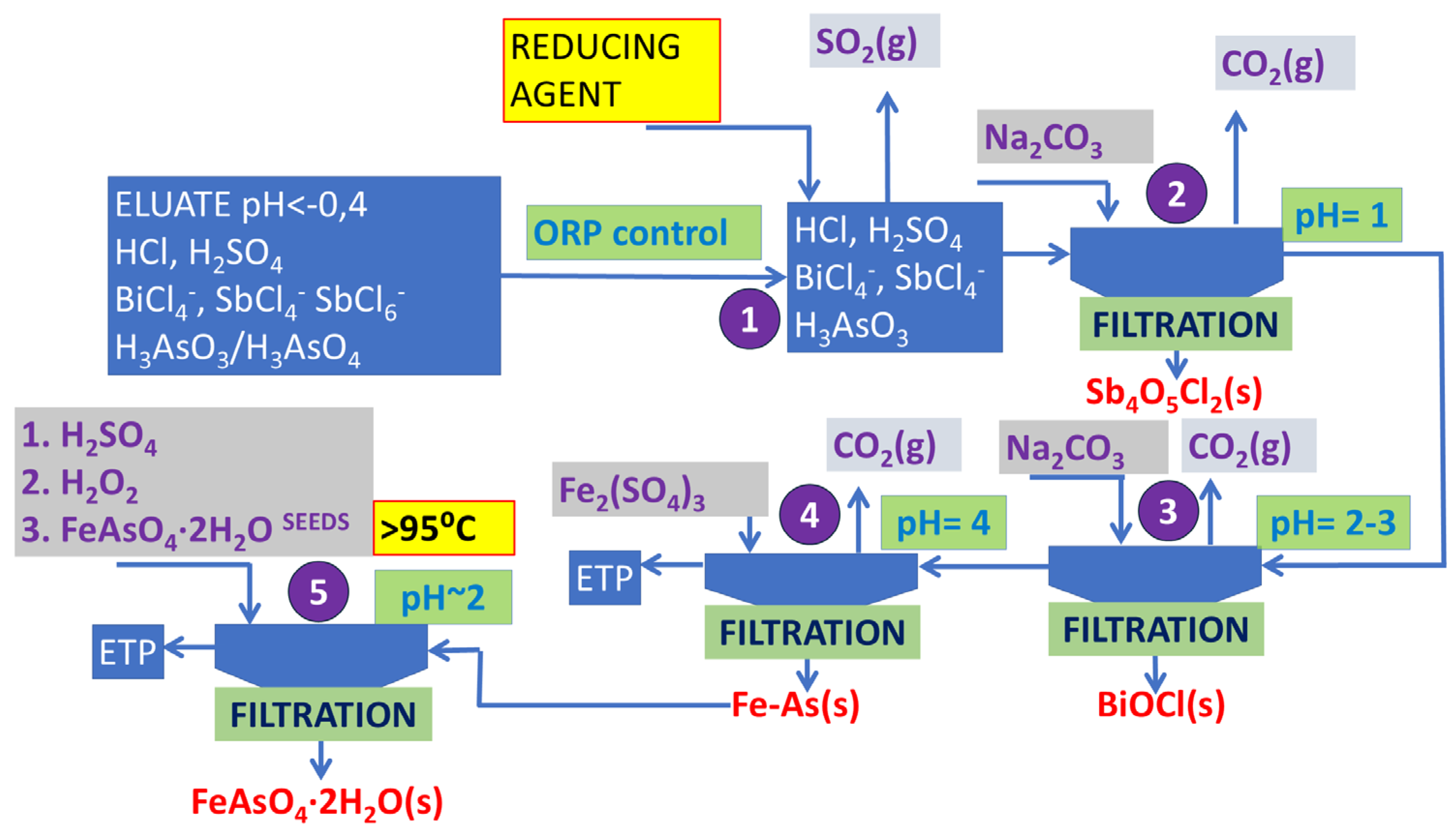
35]. The methodology was summarized graphically in
Figure 1.
Process stabilization can be achieved by reducing As and Sb from the (V) to (III) oxidation state [
36]. Sulfur dioxide (SO
2 (g)) has been identified as an efficient reducing agent for As reduction, predominantly in industry, where access to a sulfur dioxide stream is easy [
37]. However, its application in a pilot plant operated outside the smelter is problematic. Therefore, in the piloting, sodium bisulfite (NaHSO
3) was used. Its dissolution in acidic media forms a sulfur dioxide gas—a reducing agent (Equations (1)–(3)).
A two-step selective precipitation process of Sb and Bi with precise control of the ORP and pH was applied. Beyond the recovery of valuable elements, the research also emphasizes the sequestration of As.
2.4. Pilot-Scale Tests
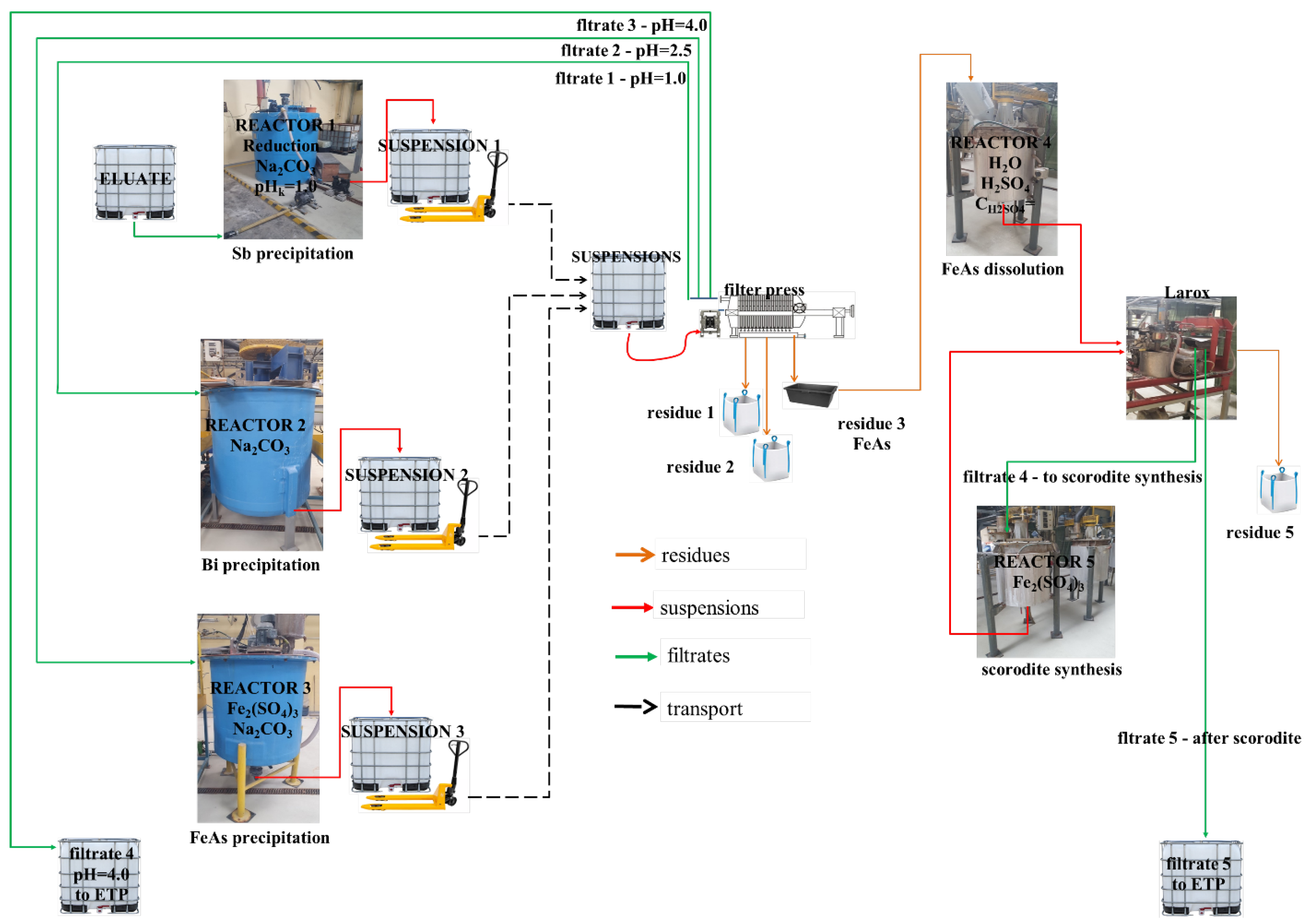
The pilot plant was composed of five reactors: a ventilated closed reactor (No. 1) with a capacity of 1.3 m
3, equipped with a stirrer, feeder, and a control loop (peristaltic pump, pH meter, ORP); reactors (No. 2 and 3) with capacities of 1.7 m
3 and 1.0 m
3, respectively, both equipped with stirrers and a continuous pH measurement control loop; two 80 dm
3 jacketed reactors (No. 4 and 5), heated by steam, operated in a batch mode (
Figure 2).
The experimental approach started with arsenic(V) reduction, using sodium bisulfite (NaHSO
3). The reduction progress was monitored by observing changes in ORP from 490 mV down to the value of 300–350 mV. Once the value reached a stabilized state, the precipitation of Sb as antimony oxychloride (Sb
XO
XCl
X, hereinafter referred as antimony concentrate as well) was triggered by the addition of the neutralizing agent: specifically, Na
2CO
3. The reaction was carried out until pH 1 was obtained, and additionally stirred for 0.5 h until all effervescence had stopped. Any pH decay was corrected by the addition of a neutralizing agent. These stages were executed in reactor No. 1, as illustrated in
Figure 2. Comparatively, NaHCO
3 was applied as the neutralizing agent; however, because of the lower sodium amount per mole of substance, much more reagent had to be used. This resulted in a bigger evolution of CO
2, significantly decreasing the temperature of the reaction mixture down to 4–6 °C, hindering the pump and presses from working.
Due to the extremely low pH of eluate (−0.5) and the presence of As, protective coatings were implemented for all metal elements of the reactor to prevent them from contacting the electrolyte with metal, as this may lead to the formation of hydrogen and the evolution of arsenic hydride (arsine). Reactor No. 1 was made of fiber-reinforced plastic, while the metal-made blade stirrer was coated with a smooth and thick layer (1 mm) of ethylene tetrafluoroethylene (ETFE), certified to withstand process conditions. Neutralization from highly acidic negative pH values up to 1 lead to the evolution of a significant amount of CO
2, as well as SO
2, and a sudden increase in froth formation, doubling the total volume of the neutralized solution (Equations (4) and (5)).
Once a pH of 1 was achieved, the SbOCl slurry was pumped to the buffer container and, after sedimentation for 2 h, pumped to a filter press. Intermediate buffer containers were applied for two primary reasons: firstly, to facilitate the settling of the reaction slurry, and secondly, to allow sufficient time for crystal growth and the formation of larger agglomerates. Following each phase separation, the filter press plates underwent washing with water under pressure to prevent cross-contamination. Subsequently, during the second neutralization stage, at a pH as high as 2.5 in reactor No. 2, the production of BiOCl slurry was achieved (Equations (6) and (7)).
Spent solution resulting from neutralization still contained a residual amount (2–3 g/dm
3) of As, necessitating effective management. A proposed solution involves converting As into a sparingly soluble compound, i.e., scorodite. This transformation requires the transition of the chloride-based environment of the eluate into a sulfate-based one, which is appropriate for scorodite precipitation. As a result, the idea was to remove As from chloride solution by adsorbing it onto an iron (Fe) compound in reactor No. 3, followed by dissolution of the resultant solid material into sulfuric acid (H
2SO
4) solution in reactor No. 4. In this operation, As and Fe passed to a liquid-phase solution while the non-dissolved residue was separated in a filter press. This operation allowed us to preconcentrate As, adsorbing it from 800 dm
3 chloride solution and dissolving in 80 dm
3 sulfuric acid solution, resulting in an As concentration close to 20 g/dm
3. It was important to reoxidize As(III) to As(V) using 30% H
2O
2, which significantly enhanced arsenic sorption. The solution in Reactor No. 5 was used to synthesize hydrated iron arsenate (scorodite), which can be performed within 8 h, at a minimum of 95 °C, and with scorodite seeds from previous trials (30–50 g/dm
3). The proper pH of scorodite synthesis should be kept within 1.5–2.0, favorably 1.7. This compound is the most stable arsenic form that can be landfilled. Its synthesis was presented in a reaction in Equation (8).
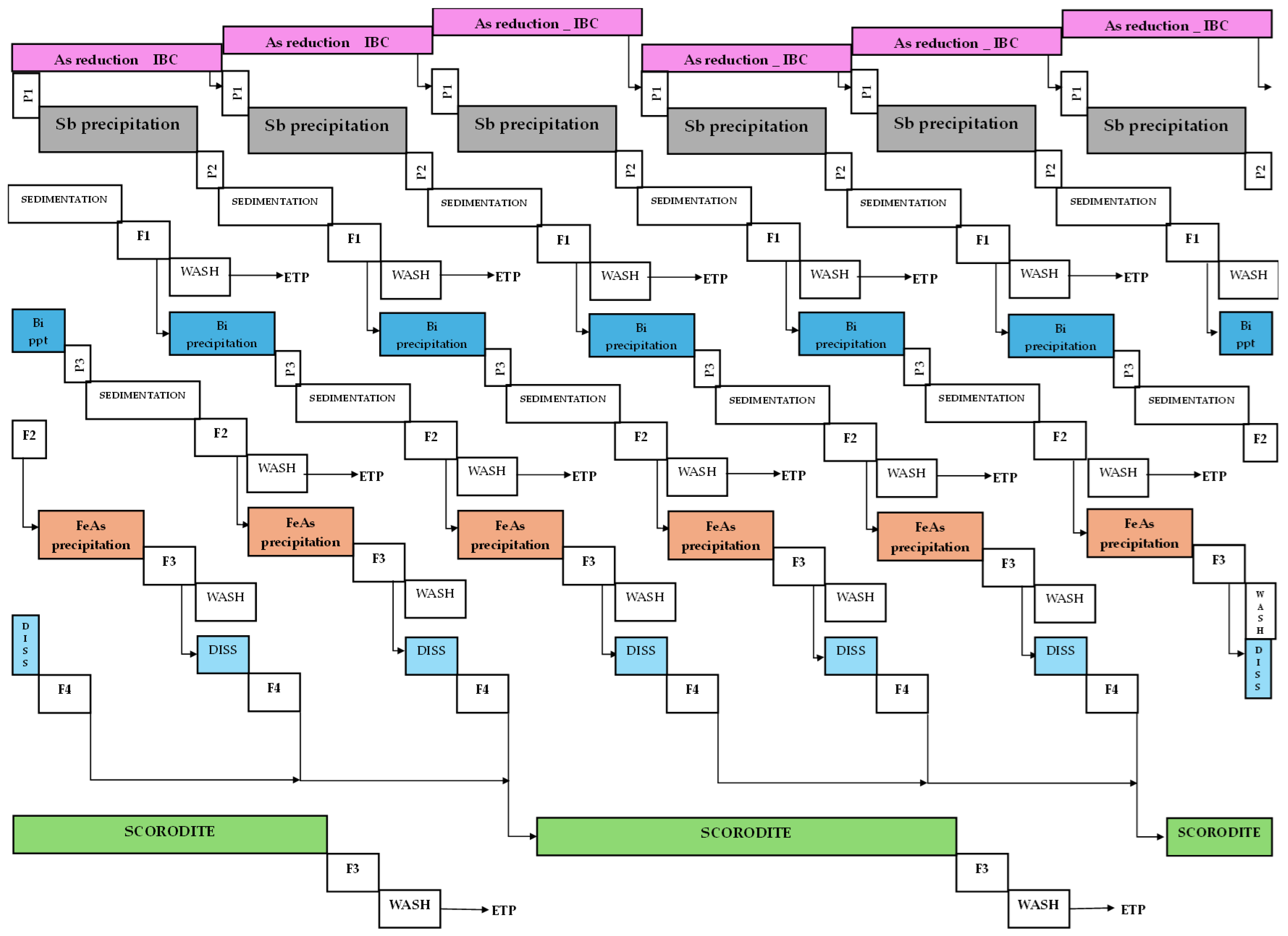
The pilot plant tests were conducted during a 12 h shift, involving a sequential cascade operation of the following unit operations: reduction, I
ST neutralization, I
ST sedimentation, I
ST filtration, II
ND neutralization, II
ND sedimentation, II
ND filtration, hydrolysis, III
RD filtration, dissolution, IV
TH filtration, scorodite synthesis, and V
TH filtration. The theoretical Gantt chart, considering a 24 h shift that is feasible at an industrial scale, was illustrated in
Figure 3.
3. Results
The first stage of developed technology involves the reduction of As(V), and potentially Sb(V) as well. The objective of this operation is to enhance the selectivity of separation of As from Sb and Bi. Arsenic(V) tends to precipitate at a very low pH, which may lead to contamination of the Sb concentrate. The amount of the reducing agent was generally set to 8 g/dm3, based on laboratory tests. The reduction time ranged from 2 to 4 h, with the preference to stabilize ORP in the range of 300–350 mV; however, extending time to 6 h would be beneficial. Subsequently, a neutralizing agent was added until the required pH was achieved. Generally, approximately 130 kg of Na2CO3 was required to increase the pH of the eluate batch from −0.5 to about 1.0.
3.1. Recovery of Sb
Data concerning the precipitation of SbOCl, specifically Sb
4O
5Cl
2, within 11 trials (SC1–SC11) of the first portion of the eluate, and 17 trials (SC12–SC28) of the second portion of eluate, were presented in
Table 2. The table provides a quantitative analysis of Sb, As, and Bi, highlighting these crucial elements in the process.
Variations in Sb recovery across different processes were attributed to differences in the mixing time of the slurry, adjusted to pH 1. In certain trials, adjustments were implemented by introducing an additional dose of the neutralizing agent following the stabilization of pH and ORP. However, in general, Sb was recovered with an efficiency ranging 95–99%. The concentration of As in filtrates ranged from 2.5 g/dm3 to 3.9 g/dm3 (IST piloting). With an initial As concentration as high as 4.22 g/dm3, the As losses as a result of coprecipitation ranged from 8 to 40 wt.%. In the IIND piloting, As concentration decreased from 3.15 g/dm3 to 1.75–2.50 g/dm3, resulting in approximately 40–62% As loss after the recovery of the Sb product. The amount of Sb concentrate per process was 7–10 kg (IST) and 7–14 kg (IIND) of wet material, with filter cake thickness ranging from 6 to 13 mm.
The quantitative analysis of the produced Sb4O5Cl2 revealed variations in the Sb content, ranging from 20 to 50% (depending on the level of contamination). The theoretical elemental composition of Sb4O5Cl2 is expected to be 76.3% Sb, 12.5% O, and 11.1% Cl, respectively. In comparison, for SbOCl, the theoretical composition is 70.3% Sb, 9.2% O, and 20.5% Cl, respectively. Discrepancies in the actual composition results from the coprecipitation of As and Bi, potential presence of other oxychlorides homologs, and the inclusion of hydrated water molecules in the final product. Antimony oxychloride serves as a favorable substrate for the transformation of Sb species into commercially valuable Sb(III) oxide. Two methodologies were adopted to convert Sb4O5Cl2 into Sb2O3. In the first chemical approach, Sb4O5Cl2 was treated with NaOH solution. The materials collected from all trials were mixed in a 400 dm3 reactor in two batches. Each process involved 300 dm3 of demi water, 15 kg of NaOH, and an equal portion of Sb concentrate. The conversion process was carried out for 2.5 h at 75 °C (the reactor was heated using a steam pumped to a heating mantle). Subsequently, the slurry was filtered (9 min filtration, two bar and eight bar press) and washed with 25 dm3 of demi water. Two filter cakes were produced, weighing 37.7 kg, with a cake width of 22 mm, and 35 kg, with a cake width of 21 mm, respectively. The water content was determined to be 14.3%.
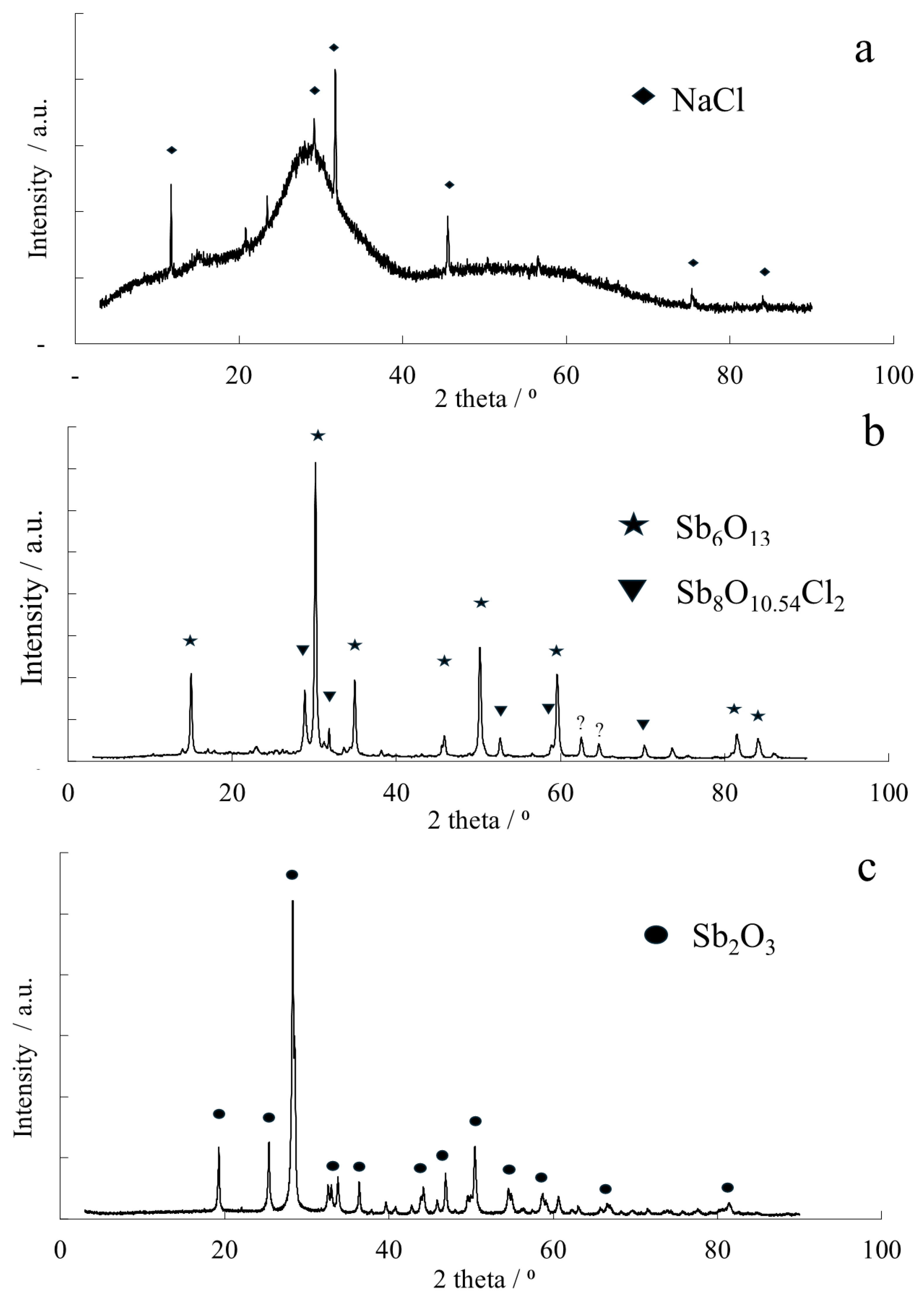
In the second approach, a small portion of Sb concentrate (50 g) was placed in a tubular furnace (Carbolite, Hope, UK) with a constant heating zone of 30 cm. The tube was flushed with nitrogen gas, and the temperature was set to 800 °C. Once the temperature was reached, it was maintained for the next hour, and the process was then cooled to room temperature. XRD patterns depicting the precipitated Sb
4O
5Cl
2 and materials from its thermal and chemical conversion are illustrated in
Figure 4.
The recovered Sb
4O
5Cl
2 demonstrated a highly amorphous nature, as evidenced by the absence of any significant crystalline signal in the diffractogram (
Figure 4a). The sole crystalline phases that were identified pertain to sodium chloride (NaCl, Card No. 01-083-1728), suggesting that the washing process was insufficient to eliminate interstitial impurities. Under inert atmosphere, the thermal treatment resulted in a partial conversion of Sb
4O
5Cl
2 into antimony oxide (Sb
6O
13, Card No. 00-033-0111); however, traces of oxychloride, specifically identified as onoratoite (Sb
8O
10.54Cl
2) (
Figure 4b), were found as well. In contrast, the chemical conversion conducted in the hot NaOH solution proved highly effective, resulting in the exclusive formation of crystalline antimony oxide (Sb
2O
3, Card No. 00-011-0689), as confirmed by XRD (
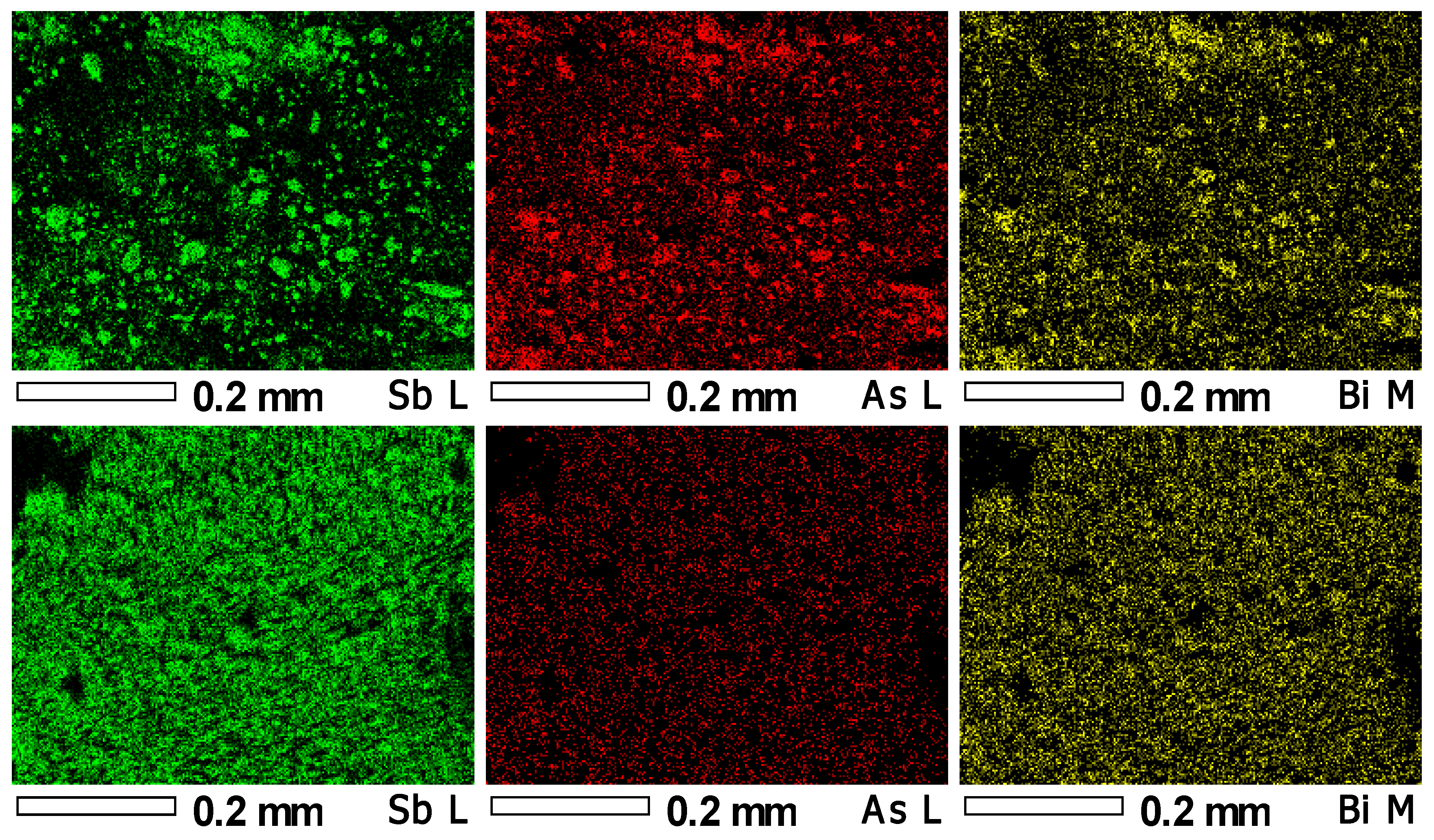
Figure 4c). This chemical approach proved effective in purifying the Sb product from As species, forming water-soluble arsenates. Consequently, the As content in the product significantly decreased from the initial 8–18 wt.% to as low as 0.2 wt.%. The arsenates-containing spent solution has to be further processed by effluent treatment plant, or acidified and mixed with the Fe-As solution for scorodite precipitation. Energy dispersive spectroscopy allowed us to map the presence of antimony, arsenic, and bismuth content within the freshly precipitated antimony oxochloride and chemically produced antimony oxide—
Figure 5.
This analysis clearly showed that alkali treatment of antimony oxochloride may significantly reduce the amount of arsenic that reacts with sodium hydroxide and passes to the solution. The mass loss resulted in concentration of non-dissolving elements; therefore, some bismuth may still be present, but after alkali treatment, any big agglomerates cannot be observed.
3.2. The Recovery of Bi
The solution from the filtration of SbOCl was further neutralized until the pH was 2.5, or favorably 2.7, resulting in the precipitation of BiOCl. Data concerning quantitative analysis of antimony, arsenic, and bismuth in the solution after bismoclite precipitation were presented in
Table 3. Trials of the first (SC1–SC11) and second piloting (SC12–SC28) were presented.
The produced bismoclite (BiOCl, Card No. 00-006-0249) was then treated with NaOH, in a process that, in contrast to Sb
4O
5Cl
2, serves not for conversion but rather for purification from As. This purification was performed using 400 dm
3 of demi water, 20 kg of NaOH, and 113 kg of wet Bi concentrate from all trials. The slurry was mixed for 1.5 h at an ambient temperature. Due to filtration challenges (BiOCl may be sticky), the filtration process was divided into two smaller portions. The product from each portion was subsequently washed with 50 dm
3 of demi water. In total, 50.9 kg (35 mm cake width) and 41.1 kg (30 mm cake width) of wet mass were produced. Additionally, the material was repulped and chosen as a superior purification method, compared to washing on a filter press. This was performed in 400 dm
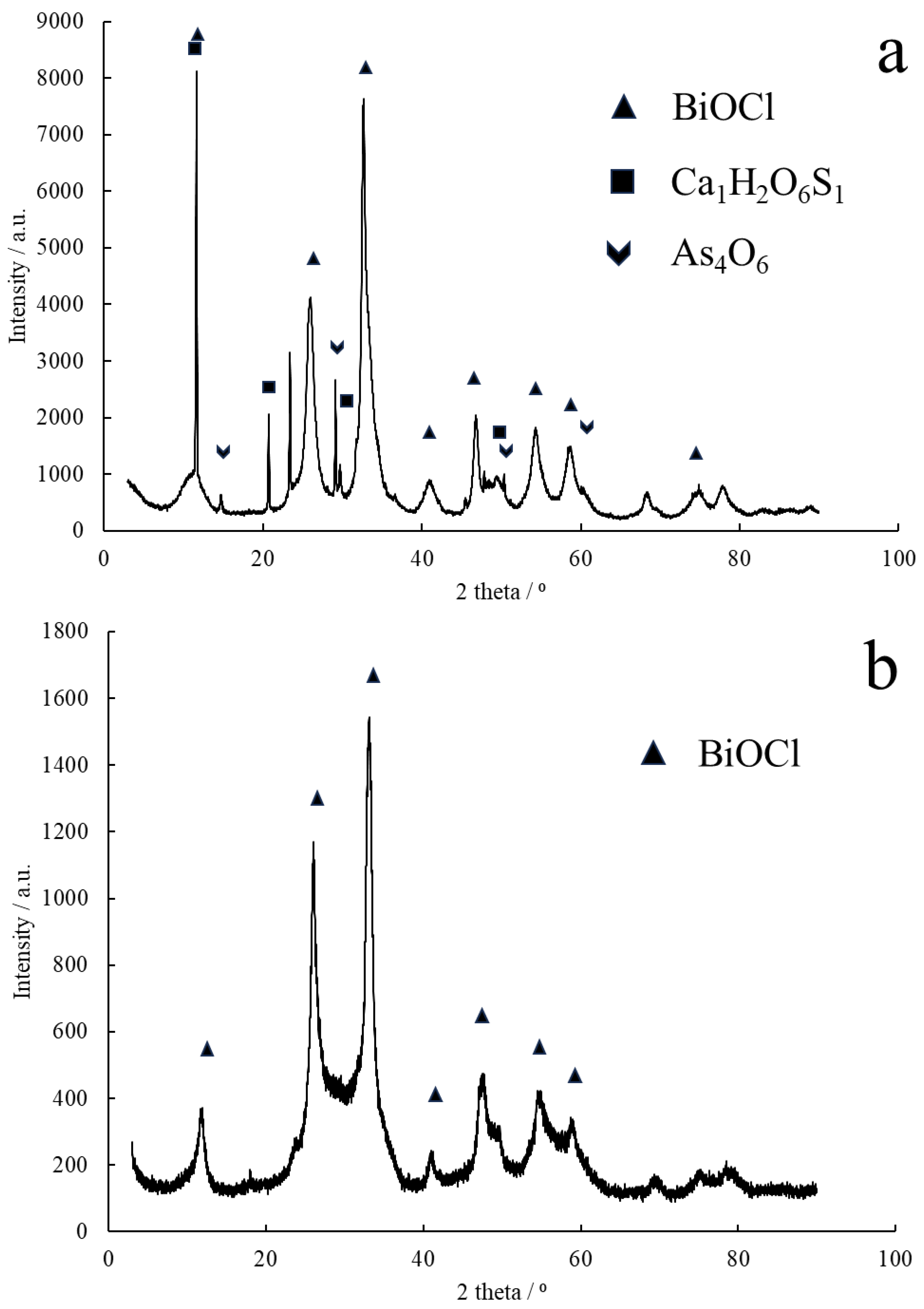
3 of demi water at an increased temperature of 60 °C. The result was 44.2 and 40.6 kg of wet mass with humidities of 40% and 39.3%, respectively, leading to dry masses of 26.5 kg and 24.3 kg, respectively. In total, 50.8 kg of dry mass of pure Bi concentrate (BiOCl) was obtained. The compound purity was 1.69 wt.% As and 2.19 wt.% As in each portion of produced material, while the Bi content was 56 wt.% and 53 wt.%, respectively. Qualitative phase analysis of obtained purified Bi concentrate and raw bismoclite precipitated in piloting is illustrated in
Figure 6. Raw bismoclite additionally contained some arsenolite (Card No. 01-084-7615) and hydrated calcium sulfate (Card No. 90-13-165).
3.3. Arsenic Sequestration
The solution with a depleted Sb and Bi was subsequently treated with an Fe compound to sequester As in a solid phase. The following approach was applied: iron(III) sulfate (Fe
2(SO
4)
3·5H
2O, min. 75%, ChemPur) was added to molar deficiency 0.7 Fe/1.0 As, and the pH was increased to approximately four by Na
2CO
3, enabling hydrolysis and precipitation of the Fe compound, with subsequent sorption of As on it. In numerous processes, it was observed that achieving total recovery of As is impossible, and a residual amount (0.2–0.4 g/dm
3) often persists in the solution. It was identified that the oxidation state of As, resulting from NaHSO
3 treatment, hinders maximum sorption. Consequently, prior to the addition of Fe (III), 30% hydrogen peroxide solution (H
2O
2) was added, to oxidize As(III) to As(V). This operation had a significant impact, leading to a considerable reduction in the As concentration in filtrate to 0.004–0.05 g/dm
3. The quantitative analysis of the obtained hydrolyzed and sorbed FeAs intermediate compound is presented in
Table 4.
The As concentration in the FeAs precipitate ranged from 20 to 28%, producing approximately 15 kg of wet mass in each process. Considering a 45% humidity level, this resulted in 6–10 kg of dry mass. Only about 40% to 60% of the initial As content of eluate can be used in the synthesis of iron arsenate. Additionally, spent solutions from SbOCl and BiOCl purification stages can be after the acidification used here, fulfilling the waste management of arsenic effluents.
Next, the obtained FeAs intermediate was dissolved in 80 dm
3 of 5–10 wt.% H
2SO
4 solution. The temperature increase during the process was only due to the heat of the dissolution reaction, usually in the range of 35–42 °C. Filtration was performed primarily to confirm the complete dissolution of the material. The filtrates were combined in a single IBC container. Quantitative analysis revealed As concentrations in the range of 13 to 27 g/dm
3. After dissolution, the combined filtrates exhibited an As content of 19.5 g/dm
3 and an Fe content of 10 g/dm
3. A part of this filtrate was transferred to a 400 dm
3 steam-heated reactor (with heating mantle), with the temperature set to 95 °C. Scorodite seeds were added, which were the product of a previous process. Iron(III) was added to increase the Fe/As molar ratio from 0.7/1.0 to 1.3/1.0. The net volume of the reaction mixture was 250 dm
3. Once the desired temperature was reached, the process started, and the pH was adjusted by Na
2CO
3 to maintain a value within the range 1.4–2.0. The produced scorodite suspension was filtered using a Larox filter press. The final concentration of elements after the scorodite synthesis is presented in
Table 5.
Depending on the trial parameters, such as the frequency of pH stabilization, residence time, and any deviations in temperature, the varied final As concentrations were observed. The highest recovery of As was approximately 80%. Analysis indicated the presence of residual Fe in the reactor, suggesting that with extended residence time, it could be possible to remove even more As, given the time-dependent nature of scorodite synthesis. It is important to note that the analysis of selected filtrates revealed the presence of Cl in the solution after the FeAs dissolution in H
2SO
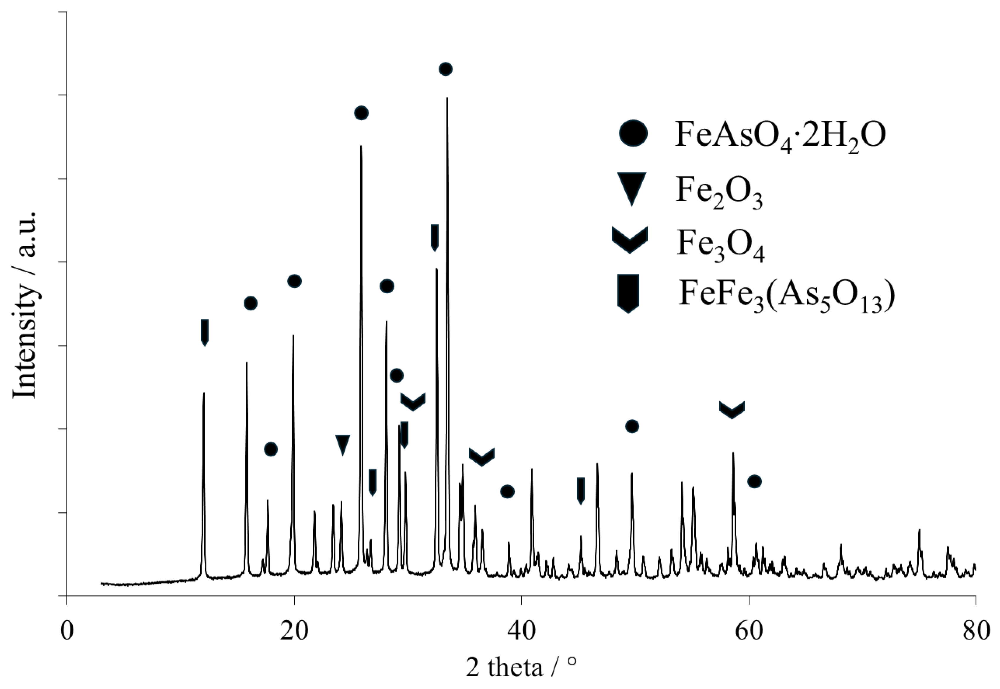
4. This was probably caused by occlusion and contributed to the challenges in achieving total As removal. The quantitative analysis showed that the content of As and Fe in the obtained scorodite ranged from 30.5 to 36.3 wt.% and 20.3–27 wt.%, respectively. Additionally, small amounts of Bi and Na were found in the product: approximately 1.5 wt.% and 0.3 wt.%, respectively. The XRD pattern of the produced scorodite (Card No. 01-076-9861) is presented in
Figure 7, while EDS images are in
Figure 8.
It was shown that except for arsenic and iron, some amounts of sodium can be found as well, which results from FeAs intermediate precipitation and its dissolution in sulfuric acid solution. This should be washed with water prior to landfilling scorodite.
4. Conclusions
This paper explores the recovery of Sb and Bi from an acidic chloride eluate from the ion exchange unit of a Cu electrolyte purification plant. The selective separation of these elements poses a challenge, regardless of the technique used.
In this study, a two-step selective precipitation method was applied, resulting in the production of Sb4O5Cl2 and BiOCl concentrates. Although the developed technology successfully recovered the majority of these elements, both concentrates were contaminated with As, which coprecipitated over a broad range of pHs. Enhancement of As and Sb separation can be obtained by reducing the oxidation states of these elements from (V) to (III), favorably using sodium bisulfite.
The concentrates produced were purified in a NaOH solution. Solutions from purification stages can be mixed with a main process stream for scorodite synthesis after pretreatment. The final stage focused on the precipitation of sparingly soluble hydrated iron(III) arsenate(V), known as scorodite, from the Sb- and Bi-depleted solution. This stage enabled the recovery and encapsulation of more than 70% (up to 80% in optimal conditions) of As into a solid product. The entire process was initially conducted at a laboratory scale and later scaled up in a pilot installation, processing 2.5 m3 of eluate daily. The work was divided into distinct unit operations carried out in a cascade manner, with a limited continuity.
In both pilots, a total of 191 kg of Sb concentrate, 97 kg of Bi concentrate, and 163 kg of scorodite were produced (dry mass). It is crucial to highlight that the efficient removal of As was contingent on changing the chloride environment into sulfate before scorodite precipitation. The proposed technology confirmed its applicability for the processing of eluates obtained during the purification of Cu electrolytes.
