Article

Adaptive Fuzzy Feedforward Compensation for High-Precision X–Y Positioning Systems Driven by Stepper Motors

by
Emmanuel García-Galvan
1,
Antonio J. Cruz-Estrada
1,
Eduardo Vincent-Islas
1,2,
José R. Rivera-Ruiz
1,3,
Edson E. Cruz-Miguel
3,4,
Javier Calderón-Sánchez
1 and
José R. García-Martínez
3,4,*
1
Maestría en Ciencias de la Ingeniería, Facultad de Ingeniería Mecánica y Eléctrica, Universidad Veracruzana, Poza Rica 93390, Veracruz, Mexico
2
Campus Poza Rica, Universidad de Oriente, Poza Rica 93306, Veracruz, Mexico
3
Laboratorio de Control y Robótica, Facultad de Ingeniería en Electrónica y Comunicaciones, Universidad Veracruzana, Poza Rica 93390, Veracruz, Mexico
4
Análisis de Sistemas y Tecnologías Emergentes, Facultad de Ingeniería en Electrónica y Comunicaciones, Universidad Veracruzana, Poza Rica 93390, Veracruz, Mexico
*
Author to whom correspondence should be addressed.
Automation 2026, 7(4), 114; https://doi.org/10.3390/automation7040114
Submission received: 17 June 2026 / Revised: 17 July 2026 / Accepted: 22 July 2026 / Published: 23 July 2026

Abstract

High-precision X–Y positioning systems driven by stepper motors are widely used in industrial automation, manufacturing, and scientific instrumentation. However, fixed feedforward–feedback controllers may degrade when operating conditions vary, particularly as step frequency changes and the risk of synchronism loss increases. This work proposes an adaptive fuzzy feedforward–feedback controller for stepper-motor-driven X–Y positioning systems. The controller uses a Takagi–Sugeno (T–S) fuzzy inference system to adjust the proportional, derivative, and feedforward actions according to the tracking error, step frequency, and an auxiliary error-based adaptation variable. The control law is integrated with the inverse kinematics of the platform to generate synchronized step-domain commands, and a practical synchronism-preservation condition is established. Experimental validation on a NEMA 17-based X–Y platform showed accurate trajectory tracking, with a steady-state error of approximately 1.6 [ μ m ] for a trapezoidal profile. For a multi-segment trajectory, the RMSE was 0.0749 [ mm ] without load and 0.0760 [ mm ] under a 7.5 [ kg ] external load. Compared with a conventional PID controller, the proposed method reduced the RMSE from 0.1741 [ mm ] to 0.0749 [ mm ] , while preserving motor synchronism.

1. Introduction

High-precision X–Y positioning systems are fundamental components in modern manufacturing and scientific applications, including Computer Numerical Control (CNC) machining, automated inspection, laser engraving, 3D printing, additive manufacturing, pick-and-place machines, semiconductor processing, laboratory automation, and scientific data acquisition instruments such as scanning probe microscopes and astronomical telescopes. In these applications, positioning accuracy, repeatability, and motion smoothness directly influence product quality, system productivity, and data reliability [1,2,3]. Because these systems often operate under varying mechanical loads, dynamic velocity profiles, and vibration-sensitive conditions, their actuators must maintain strict synchronism and accurate trajectory tracking under continuously changing operating conditions. Stepper motors are widely used in X–Y positioning systems because of their low cost, simple implementation, high positioning resolution, and ability to operate without dedicated position sensors [4,5]. However, their performance degrades as speed and acceleration increase, since resonance, load variations, mechanical friction, and nonlinear torque–frequency characteristics can produce tracking errors, vibration, and even step loss when the commanded motion exceeds the actuator’s dynamic capabilities [6,7,8]. To address these issues, several control approaches have been proposed, including classical proportional–integral–derivative (PID) control [8,9], adaptive control, model predictive control (MPC) [10], sliding-mode control [11,12], neural-network-based control [13,14], and fuzzy logic control [15]. Although fixed-gain PID controllers are simple and widely used, their performance may deteriorate under payload variations or resonance-sensitive operating regions [16]. Moreover, many advanced methods require accurate models, high computational resources, or complex tuning procedures, which may limit their implementation on embedded motion-control platforms.
Fuzzy logic controllers are particularly attractive because they incorporate expert knowledge and handle nonlinear behavior without requiring a precise mathematical model [17]. They have been applied to robotic manipulators, autonomous vehicles, unmanned aerial vehicles (UAVs), industrial positioning systems, and motion-control applications [18,19,20,21,22], making them suitable for stepper-motor-driven systems affected by nonlinearities and uncertainty [23,24]. In parallel, feedforward compensation improves trajectory tracking by anticipating the required control effort from the reference trajectory and reducing the feedback burden [25,26]. It is commonly used to improve transient response during acceleration and deceleration [27,28,29]; however, most feedforward approaches rely on fixed compensation gains and cannot adequately adapt to load variations, operating-frequency changes, or disturbances.
In the specific area of fuzzy and adaptive control for stepper-motor positioning systems, previous studies have addressed nonlinearities, resonance, torque ripple, poor damping, and tracking degradation through several fuzzy-based strategies. Fuzzy logic control has been applied to variable-reluctance and hybrid stepper motors to reduce oscillations, overshoot, undershoot, ripple, and settling time [30,31]. Related works have also explored fuzzy gain scheduling, adaptive fuzzy position control, FPGA-based fuzzy implementation, and DSP-based fuzzy servosystems to improve dynamic response and robustness [31]. Other approaches include fuzzy sliding-mode observers for sensorless speed and position tracking [32], interval type-2 fuzzy controllers with feedback-error-learning and Kalman-filter-based adaptation for micrometer-level positioning [33], and frequency-modulation-based microstepping to improve real-time tracking and reduce loss of synchronism [34]. However, most existing studies focus on single-axis regulation, speed control, angular-position tracking, sensorless observation, or microstepping generation. Thus, limited attention has been given to low-complexity fuzzy adaptive feedforward–feedback control for stepper-motor-driven X–Y positioning systems, particularly strategies that use the step-frequency operating region as a fuzzy adaptation variable to jointly adjust feedback and feedforward actions while considering synchronism preservation in the actuator step domain.
For stepper-motor-driven positioning systems, feedforward compensation depends strongly on actuator operating conditions, since higher stepping frequencies reduce available torque and increase the risk of synchronization loss, making fixed-gain compensation inadequate over the full operating range [35,36]. Motivated by these limitations, this work proposes a T–S singleton-based fuzzy adaptive feedforward–feedback controller that adjusts the proportional, derivative, and feedforward actions using the tracking error, step frequency, and an auxiliary error-based adaptation variable. The step frequency represents the actuator operating region, while the auxiliary variable modulates the adaptation intensity without load estimation, parameter identification, or computationally intensive optimization. Thus, the proposed method improves tracking accuracy, transient response, robustness, and embedded implementation feasibility. Based on these developments, the main contributions of this work are summarized as follows:
  • A fuzzy adaptive feedforward–feedback architecture is proposed for stepper-motor-driven X–Y positioning systems, enabling online adaptation of proportional, derivative, and dynamic-effort compensation actions.
  • A T–S singleton fuzzy inference system based on Fuzzy Associative Memory (FAM) is developed to generate adaptive feedback and feedforward correction factors. The proposed scheme incorporates step frequency and an error-based dynamic-effort indicator to enable frequency-aware adaptation for improved tracking performance and synchronism preservation with low computational complexity.
  • The control architecture integrates Cartesian trajectory tracking with the inverse kinematics of the X–Y platform, allowing Cartesian references to be converted into synchronized step-domain commands.
  • Experimental validation on an X–Y positioning platform confirms improved tracking performance and motor synchronism under different operating conditions.
The paper is organized as follows. Section 2 presents the proposed adaptive control architecture, including inverse kinematics, fuzzy control integration, and synchronism-preservation analysis. Section 3 reports the experimental identification, fuzzy adaptation parameters, trajectory-tracking results, and synchronism verification. Section 4 discusses the results, and Section 5 presents the conclusions and future work.

2. Adaptive Control Architecture for the X–Y Positioning System

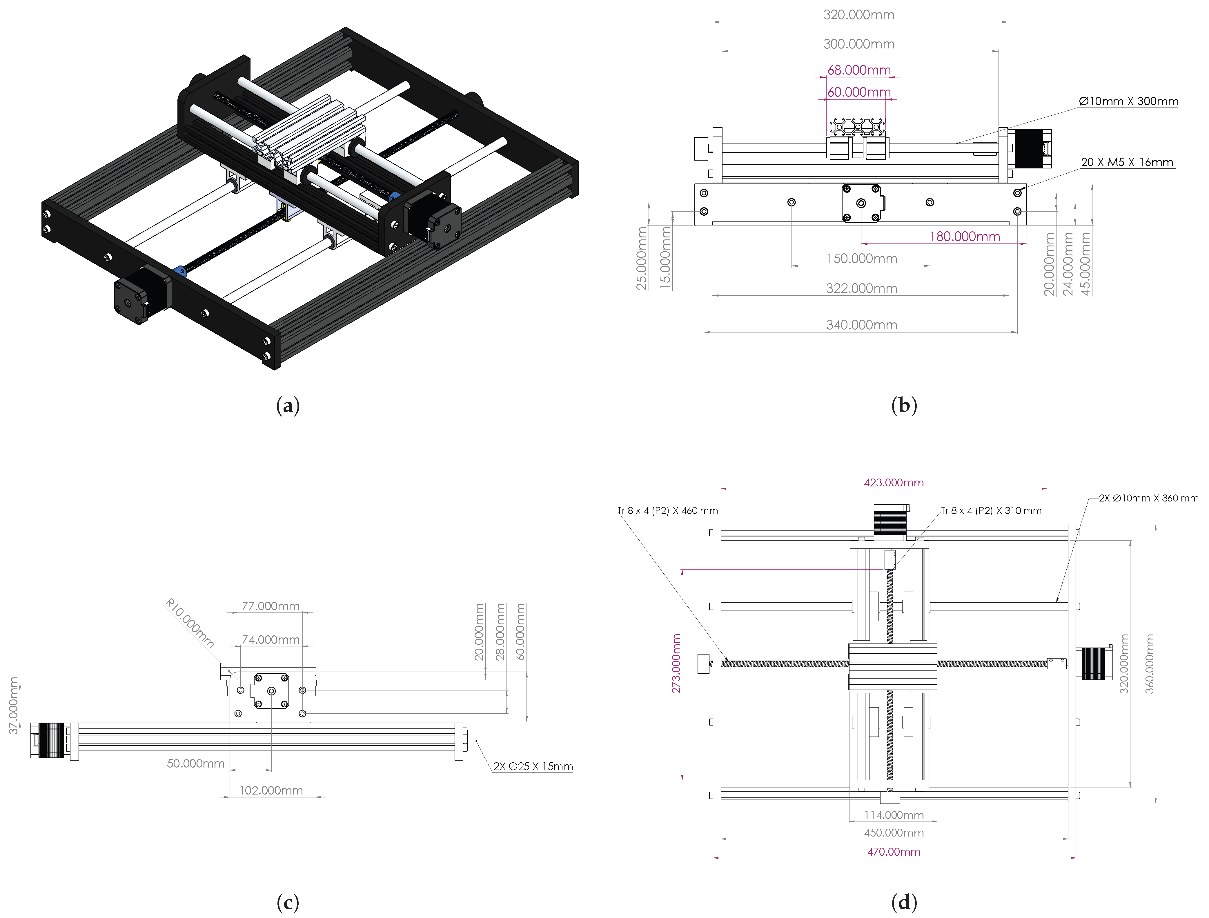
The X–Y positioning platform was built using T-Slot 2040 aluminum profiles for the main frame and movable X-axis crossbeam, providing a rigid and modular structure. Phenolic polymer plates were used for the joints, motor mounts, and shaft supports, while M5 screws ensured mechanical stability and ease of maintenance, as shown in Figure 1a. NEMA 17 stepper motors were directly coupled to Tr8×4 trapezoidal lead screws to convert rotary motion into linear displacement, with knurled knobs added for manual adjustment, as illustrated in Figure 1b. A T-slot bed provided a configurable mounting surface, and hardened steel smooth rods were used as linear guides to ensure accurate, low-friction motion along both axes, as shown in Figure 1c,d. Additional technical details regarding the mechanical components, constituent materials, primary functions, and typical applications are provided in Appendix A.

2.1. Inverse Kinematics and Step-Domain Tracking Error

For the proposed X–Y positioning system, the inverse kinematic model provides the transformation between the desired Cartesian reference and the corresponding motor-step commands. This transformation is relevant not only for trajectory generation, but also for the practical stability analysis of the stepper-motor-based motion system, since loss of synchronism occurs in the actuator domain when the commanded and actual step positions deviate beyond an admissible region.
Let the desired Cartesian position be defined by Equation (1):
q d ( t ) = x d ( t ) y d ( t ) ,
where x d ( t ) and y d ( t ) denote the desired coordinates along the X and Y axes, respectively. The measured Cartesian position of the platform is expressed in Equation (2):
q ( t ) = x ( t ) y ( t ) .
The Cartesian tracking error is then defined by Equation (3):
e q ( t ) = q d ( t ) q ( t ) = e x ( t ) e y ( t ) .
The linear resolution of each axis is determined by the mechanical transmission parameters, as shown in Equations (4) and (5):
k x = p x N s , x M x ,
k y = p y N s , y M y ,
where p x and p y are the lead screw pitches, N s , x and N s , y are the motor steps per revolution, and M x and M y are the microstepping factors. Thus, k x and k y represent the linear displacement generated by one commanded step in each axis.
Using these resolutions, the inverse kinematic transformation from Cartesian space to actuator-step space is given by Equation (6):
N d ( t ) = K 1 q d ( t ) ,
where the desired step vector and the inverse resolution matrix are defined in Equations (7) and (8):
N d ( t ) = N x , d ( t ) N y , d ( t ) ,
K 1 = 1 k x 0 0 1 k y .
Similarly, the measured step position associated with the actual Cartesian position is obtained using Equation (9):
N ( t ) = K 1 q ( t ) .
Therefore, the tracking error in the actuator-step domain can be written as Equation (10):
e N ( t ) = N d ( t ) N ( t ) = K 1 e q ( t ) .
Explicitly, Equation (11) gives the step-domain error for each axis:
e N ( t ) = e x ( t ) k x e y ( t ) k y .
This relationship shows that the Cartesian tracking error is directly mapped into the number of lost or delayed steps required to recover the desired position. Since the X–Y table is composed of two independent orthogonal axes, the inverse kinematic transformation is linear, diagonal, and bounded. Therefore, boundedness of the Cartesian tracking error implies boundedness of the step-domain tracking error, provided that k x > 0 and k y > 0 .

2.2. Adaptive Fuzzy Inference Mechanism

The proposed adaptive control strategy employs a T-S singleton-based fuzzy inference system to adjust the controller parameters online according to the operating condition of the stepper motor. The fuzzy system generates three adaptive coefficients associated with the proportional, derivative, and feedforward actions, which are grouped in the adaptive gain vector defined by Equation (12):
( α K p , α K d , α f f )
The inference mechanism considers three input variables: the tracking error e ( t ) , the step frequency f s t e p ( t ) , and an auxiliary adaptation variable γ ( t ) . The tracking error quantifies the deviation between the desired and actual positions, whereas the step frequency characterizes the actuator operating region and captures frequency-dependent effects associated with stepper-motor operation. In the proposed implementation, the step frequency is computed as f s t e p ( t ) = | v ( t ) | d s t e p , where v ( t ) is the commanded linear velocity of the positioning stage and d s t e p denotes the linear displacement generated by a single motor step. The auxiliary adaptation variable is defined as γ ( t ) = k e | e ( t ) | , where k e is a scaling coefficient, and is used to increase the adaptation level when larger corrective actions are required.
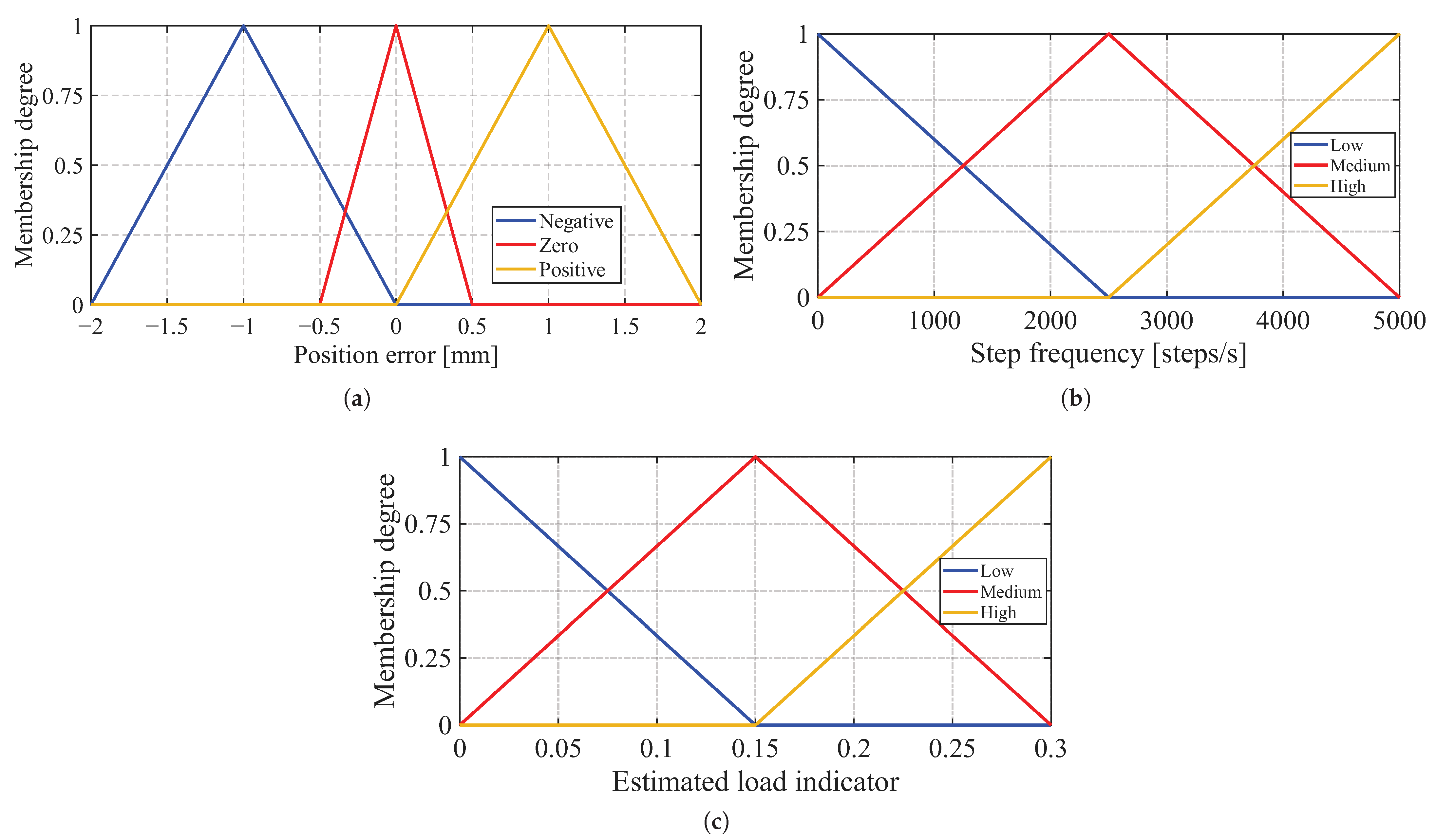
Each input variable is represented by three triangular membership functions labeled low, medium, and high. Triangular membership functions were selected because of their low computational complexity, numerical simplicity, and suitability for real-time embedded implementation, where x i L , x i C and x i R represent the lower, center and upper bound, respectively. The fuzzy rule base is organized through a and follows a T-S singleton-based. Because step frequency plays a fundamental role in stepper-motor performance and synchronism preservation, the rule base was explicitly designed to incorporate frequency-dependent gain adaptation. The adaptive behavior is primarily determined by the interaction between tracking error and step frequency, while γ ( t ) acts as a modulation variable that adjusts the adaptation intensity according to the current tracking condition.
Figure 2 presents the membership function distributions associated with the input variables of the proposed fuzzy controller. Figure 2a illustrates the membership functions defined for the stepper motor position error. Figure 2b shows the membership functions corresponding to the step frequency, while Figure 2c presents the membership function distribution associated with the adaptation variable. The complete membership funtion distributions is summarized in Table 1, Table 2 and Table 3.
The singleton consequents define the adaptive correction factors associated with the proportional, derivative, and feedforward actions of the controller. Through the T-S inference mechanism, these consequents are combined to generate the adaptive coefficients employed by the proposed control law. The complete rule base is presented in Table 4, Table 5 and Table 6. The general inference rule adopted by the controller is defined in Equation (13):
R i : IF   e ( t )   is   A i   AND   f s t e p ( t )   is   B i   AND   γ ( t )   is   C i   THEN   [ α K p , α K d , α f f ]
The complete rule base is summarized in Table 4, Table 5 and Table 6. Table 4 presents the adaptation rules associated with the low linguistic level of γ ( t ) .
Table 5 presents the adaptation rules associated with the medium linguistic level of γ ( t ) .
Table 6 presents the adaptation rules associated with the high linguistic level of γ ( t ) .
The activation level of each rule is calculated using the minimum operator, as defined in Equation (14).
w i = min { μ A i ( e ) , μ B i ( f s t e p ) , μ C i ( γ ( t ) ) }
Once the active rules are evaluated, the output of the fuzzy system is obtained through the weighted average aggregation defined in Equation (15).
α = i = 1 N w i z i i = 1 N w i
The adaptive gains are updated online according to Equations (16) and (17).
k p ( t ) = α K p ( t ) k p
k d ( t ) = α K d ( t ) k d
The feedforward term is incorporated to anticipate the control action required during acceleration and deceleration phases of the trajectory. Since trajectory-following performance is strongly influenced by the reference acceleration, the constant gain k f f is associated with a r ( t ) to improve transient response and reduce the corrective burden on the feedback loop. The resulting adaptive control law is defined in Equation (18):
u ( t ) = k p ( t ) e ( t ) + k d ( t ) e ˙ ( t ) + k f f a r ( t ) + α f f ( t ) γ ( t ) k n
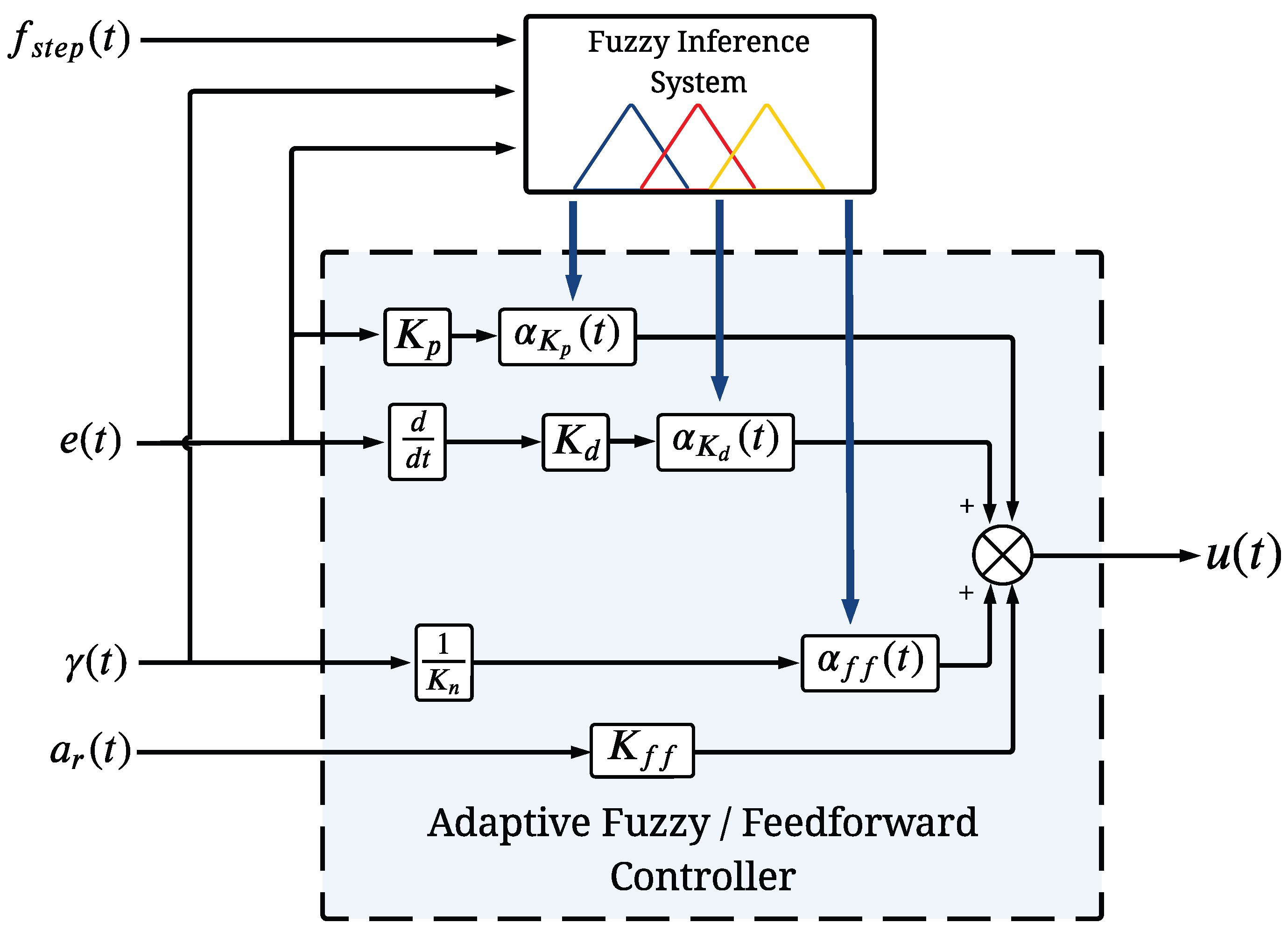
where k n is a positive normalization constant used to scale the auxiliary adaptation variable γ ( t ) . This control law combines adaptive feedback and feedforward actions to improve trajectory-tracking performance under varying operating conditions while maintaining the low computational complexity required for real-time embedded implementation. Figure 3 presents the internal structure of the proposed adaptive fuzzy feedforward controller, including the input variables, fuzzy inference mechanism, and adaptive gain generation process.

2.3. Integration of Inverse Kinematics and Adaptive Fuzzy Control

The proposed strategy combines the inverse kinematic model and the adaptive fuzzy feedforward controller into a unified Cartesian-space formulation. The inverse kinematic transformation establishes the deterministic relationship between the workspace and the actuator domain through Equation (6), while the adaptive controller regulates the Cartesian tracking error defined in Equation (3). Consequently, both modules are mathematically coupled through the error propagation between Cartesian coordinates and motor steps.
For each axis, the adaptive fuzzy inference system receives the local operating conditions composed of the tracking error, the instantaneous step frequency, and the adaptation variable. Accordingly, the input vector associated with the i-th axis is defined by Equation (19).
z i ( t ) = e i ( t ) f s t e p , i ( t ) γ i ( t ) , i { x , y } ,
The resulting adaptive coefficients are incorporated into the control law of Equation (18) to obtain the adaptive gains of each actuator. By considering both axes simultaneously, the adaptive gain matrices can be written as shown in Equation (20).
K p ( t ) = K p , x ( t ) 0 0 K p , y ( t ) , K d ( t ) = K d , x ( t ) 0 0 K d , y ( t ) ,
where
k p , i ( t ) = α K p , i ( t ) k p , k d , i ( t ) = α K d , i ( t ) k d , i { x , y } ,
according to Equations (16) and (17).
Similarly, the adaptive feedforward coefficients are grouped into the matrix defined in Equation (21).
A f f ( t ) = α f f , x ( t ) 0 0 α f f , y ( t ) .
Therefore, the adaptive control law for the complete X–Y positioning system is given by Equation (22).
u ( t ) = K p ( t ) e q ( t ) + K d ( t ) e ˙ q ( t ) + K f f a r ( t ) + A f f ( t ) γ ( t ) K n ,
where
e ˙ q ( t ) = e ˙ x ( t ) e ˙ y ( t ) , a r ( t ) = a r , x ( t ) a r , y ( t ) , γ ( t ) = γ x ( t ) γ y ( t ) , u ( t ) = u x ( t ) u y ( t ) ,
The adaptive control action generated by Equation (22) is interpreted as a Cartesian correction applied to the nominal reference trajectory. Consequently, the corrected Cartesian reference is defined in Equation (23).
q c ( t ) = q d ( t ) + u ( t ) ,
where
q c ( t ) = x c ( t ) y c ( t )
represents the corrected trajectory that incorporates the adaptive compensation generated by the fuzzy controller.
Rather than directly commanding the actuator space, the corrected Cartesian reference is subsequently transformed into motor-step references through the inverse kinematic model of Equation (6). Therefore, the commanded actuator vector becomes Equation (24).
N c ( t ) = K 1 q c ( t ) ,
or equivalently,
N c ( t ) = K 1 q d ( t ) + u ( t ) .
Substituting Equation (22) into Equation (25) yields Equation (26).
N c ( t ) = K 1 q d ( t ) + K p ( t ) e q ( t ) + K d ( t ) v r ( t ) v ( t ) + K f f a r ( t ) + A f f ( t ) γ ( t ) K n ,
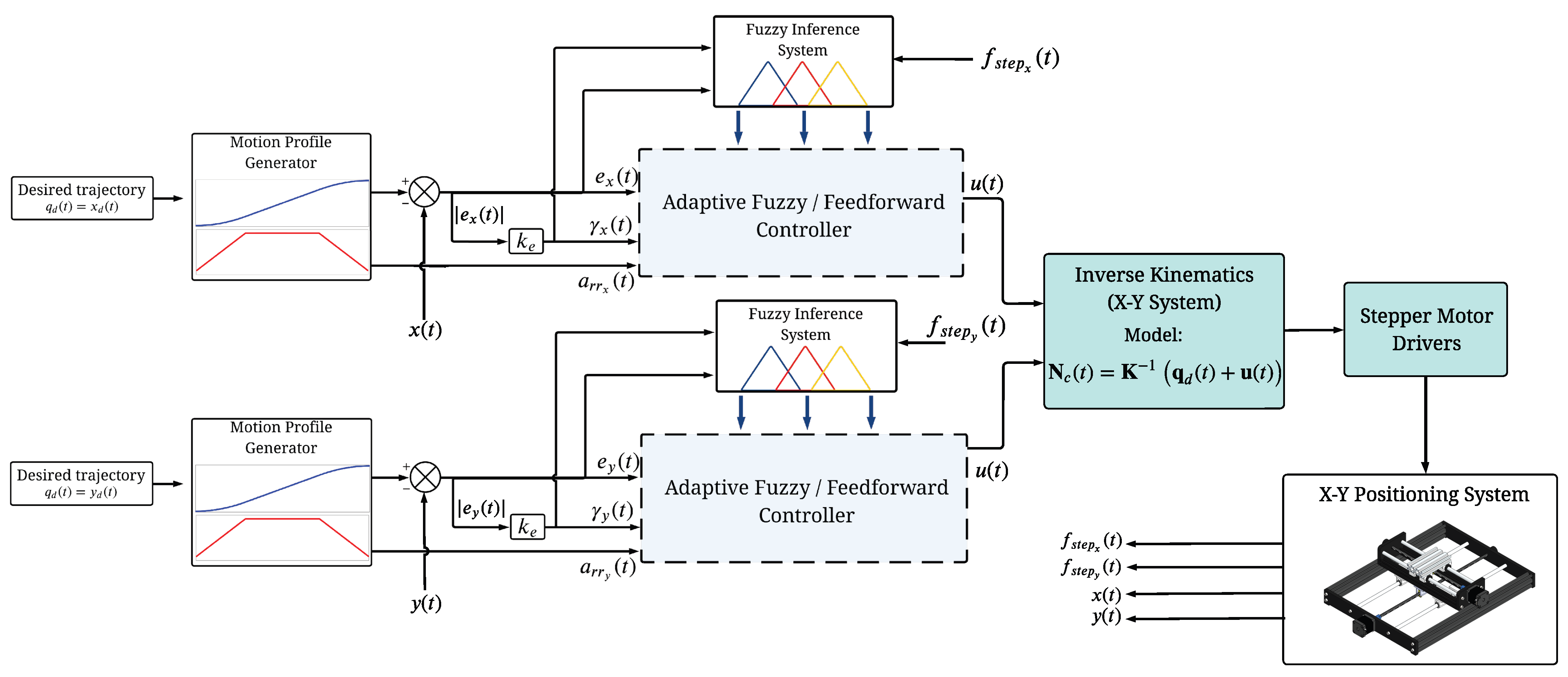
which explicitly couples the adaptive fuzzy controller with the inverse kinematic transformation. The controller generates a Cartesian correction according to the tracking conditions, while the inverse kinematic model maps the corrected trajectory into synchronized actuator-step commands. Thus, the geometric transformation remains unchanged, and the adaptive compensation modifies only the commanded trajectory to improve tracking performance and preserve actuator synchronism. Figure 4 illustrates the interaction between the motion profile generator, fuzzy inference mechanism, adaptive feedforward controller, and inverse kinematic transformation.

2.4. Practical Synchronism Preservation Analysis

For stepper-motor-driven X–Y positioning systems, synchronism preservation is directly related to the boundedness of the actuator-step tracking error. Using the inverse kinematic relationship of Equation (10), the admissible synchronization region is defined by Equation (27) as
e N ( t ) < N max ,
where N max denotes the maximum allowable step deviation before loss of synchronism.
By substituting Equation (10) into Equation (27), the synchronization criterion can be equivalently expressed in Cartesian coordinates as shown in Equation (28).
K 1 e q ( t ) < N max ,
which leads to the axis-wise bounds
| e x ( t ) | < k x N max , | e y ( t ) | < k y N max .
Since the T-S membership functions satisfy 0.90 μ i ( · ) 1.70 and the singleton consequents are finite, the weighted-average inference mechanism guarantees bounded adaptive coefficients. Therefore,
K p ( t ) < , K d ( t ) < , A f f ( t ) < ,
ensuring that the adaptive control law of Equation (22) remains bounded.
Furthermore, for bounded reference trajectories, bounded tracking errors, bounded error derivatives, and bounded reference accelerations, the adaptive correction vector remains bounded. By applying the integrated inverse-kinematic formulation of Equation (25), the commanded actuator-step vector satisfies the inequality given in Equation (30),
N c ( t ) K 1 q d ( t ) + u ( t ) ,
which shows that bounded Cartesian commands produce bounded actuator-step commands through the inverse kinematic transformation.
Therefore, if the adaptive controller maintains the Cartesian tracking error within the limits established by Equation (29), the corresponding actuator-step error automatically satisfies Equation (27), preserving motor synchronism and reducing the likelihood of step loss. Consequently, the proposed analysis provides a practical boundedness guarantee for the kinematic control architecture rather than a complete asymptotic stability proof of the electromechanical system.

3. Results

3.1. Experimental Identification and Dynamic Modeling of the Stepper Motor

The dynamic characterization of the NEMA 17 stepper motor was performed using the MATLAB (R2026a) System Identification Toolbox. Since stepper-motor systems exhibit coupled nonlinear electromechanical dynamics, the identification experiment was conducted in closed loop using a proportional controller to keep the plant within a bounded operating region, provide persistent excitation, and avoid instability or loss of synchronism. The control signal u ( t ) was used as the model input, while the measured shaft angular position θ ( t ) was used as the output. Several parametric model structures were evaluated by minimizing the prediction error between the measured and simulated responses. The best representation was obtained with the fourth-order continuous-time transfer function
G s ( s ) = 1837 s + 64.14 s 4 + 186.4 s 3 + 2.256 × 10 4 s 2 + 4655 s + 2136 .
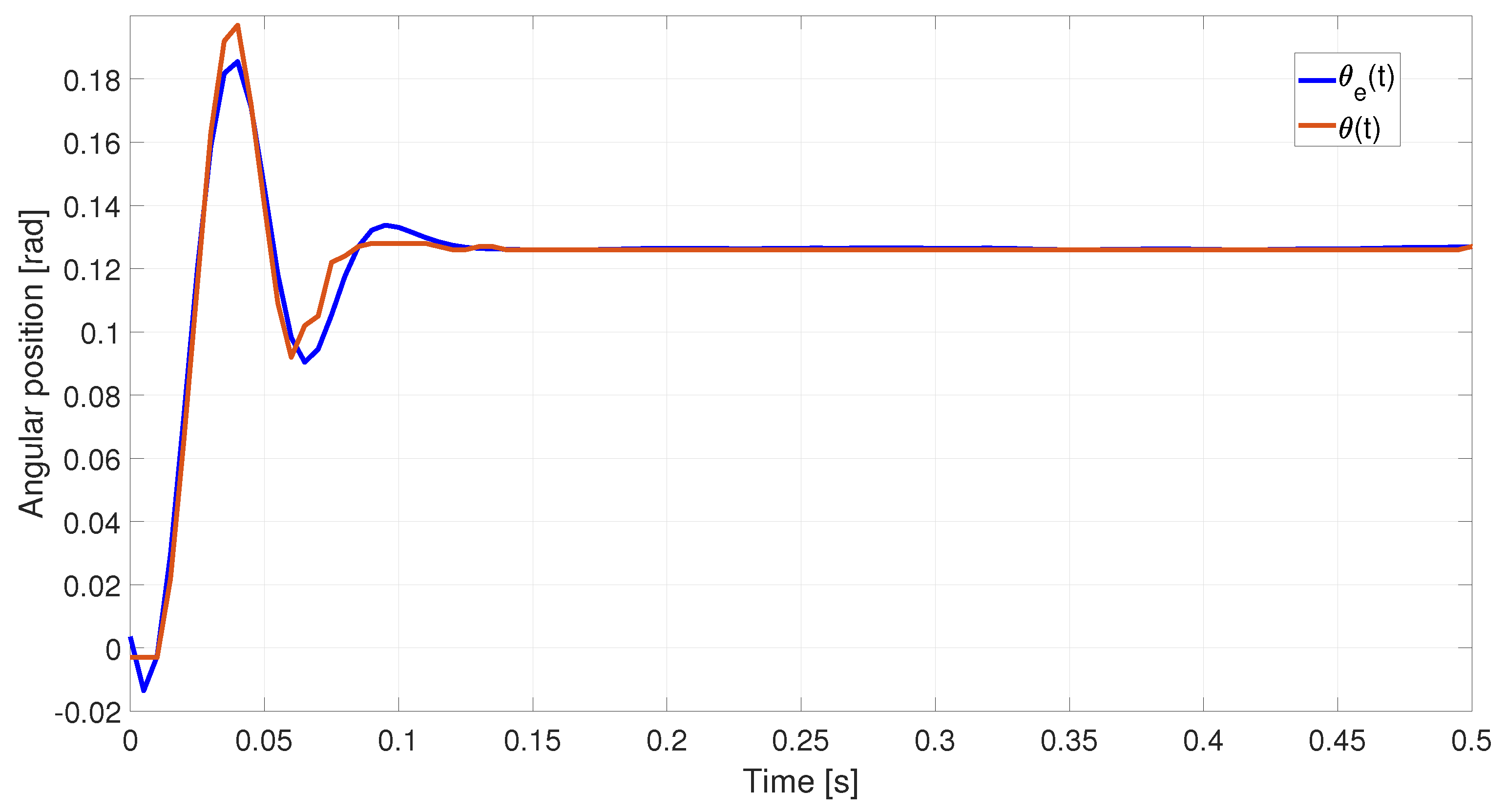
Figure 5 compares the measured angular position θ ( t ) with the simulated model output θ d ( t ) . The residual analysis and normalized root mean square error (NRMSE) yielded a goodness-of-fit of 86.51 % , indicating that G s ( s ) captures the main transient and steady-state dynamics of the NEMA 17 stepper motor and is suitable for controller development and evaluation.

3.2. Fuzzy Adaptation Parameters

The adaptive coefficients generated by the fuzzy inference system and the constant parameters employed by the controller are summarized in Table 7. The coefficient ranges correspond to the minimum and maximum singleton values defined within the FAM rule base.
The adaptive coefficient ranges in Table 7 were defined through model-based analysis and experimental tuning. The identified fourth-order model in Equation (31) was first used to establish a nominal operating region for the positioning system. Since f s t e p ( t ) directly affects the available torque and synchronism preservation, the derivative adaptation factors were increased in higher-frequency regions to provide additional damping. The proportional and feedforward factors were adjusted to improve transient tracking and reduce the corrective effort required from the feedback loop.
The singleton consequents were defined as correction factors around the nominal value of 1, where values below 1 reduce the corresponding control action and values above 1 increase it. Thus, larger tracking errors activate stronger proportional and feedforward compensation, while higher step frequencies promote greater derivative action to improve damping and reduce the risk of synchronism loss. The auxiliary variable γ ( t ) only modulates the adaptation intensity without changing the frequency-oriented structure of the rule base. The final values were refined experimentally to balance tracking accuracy, smooth control action, and synchronism preservation across the tested conditions.

3.3. Experimental Trajectory Tracking

The trajectory-tracking performance of the X–Y positioning system was assessed using the Euclidean tracking error, which provides a unified measure of the position deviation in both axes. The Euclidean error is defined in Equation (32) as
e E ( t ) = x d ( t ) x ( t ) 2 + y d ( t ) y ( t ) 2
where x d ( t ) and y d ( t ) denote the reference positions, while x ( t ) and y ( t ) represent the measured positions of the X and Y axes, respectively. The mean square error (MSE), root mean square error (RMSE), integral absolute error (IAE), integral squared error (ISE), and integral time absolute error (ITAE) were subsequently computed from the Euclidean error to quantitatively assess the tracking accuracy and robustness of the proposed adaptive fuzzy feedforward controller under different operating conditions.
The RMSE, defined in Equation (33), was used as an indicator of the overall tracking accuracy
R M S E E = 1 N s k = 1 N s e E 2 ( k )
where N s is the total number of samples.
The IAE, ISE, and ITAE performance indices are defined in Equations (34)–(36).
I A E E = 0 T | e E ( t ) | d t
I S E E = 0 T e E 2 ( t ) d t
I T A E E = 0 T t | e E ( t ) | d t
where T denotes the trajectory duration. Table 8 summarizes the main hardware and operating parameters of the experimental X–Y positioning platform. These parameters define the mechanical transmission characteristics, actuator specifications, and control sampling period used throughout the experimental validation.
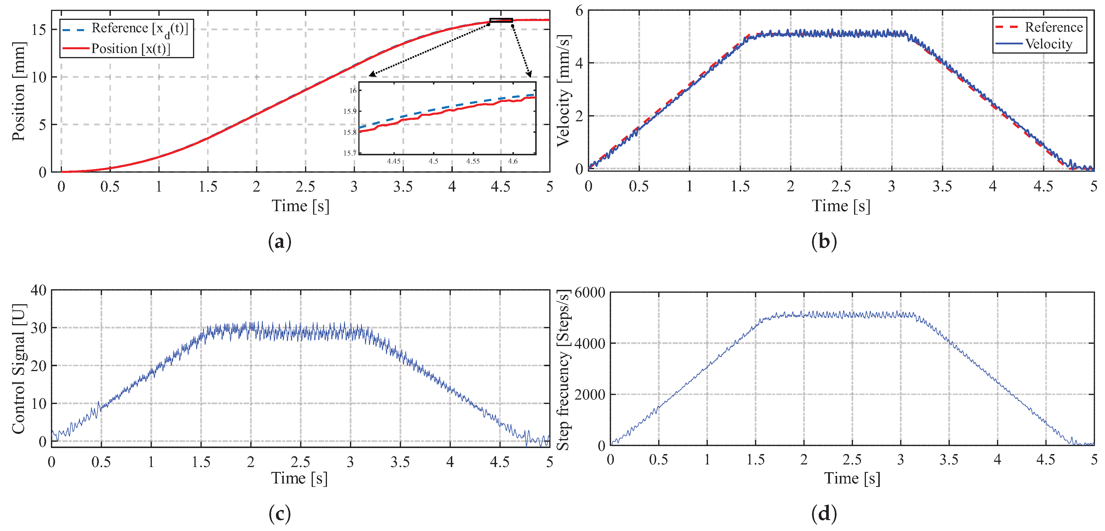
The performance of the proposed adaptive fuzzy feedforward controller was validated through a trajectory-tracking task using a trapezoidal motion profile. Figure 6a presents the position response of one of the stepper motors for a motion duration of 5 [ s ] , while Figure 6b shows the corresponding velocity tracking response, demonstrating accurate tracking of the reference profile with a maximum reference velocity of 5.09 mm s . During the position-tracking task, the X–Y positioning system achieved a steady-state error of approximately 1.6 [ μ m ] , highlighting the high precision of the proposed control strategy. Figure 6c,d illustrate the control signal and the generated step frequency, respectively, confirming that the controller produces smooth command signals while maintaining the required motion profile throughout the trajectory.
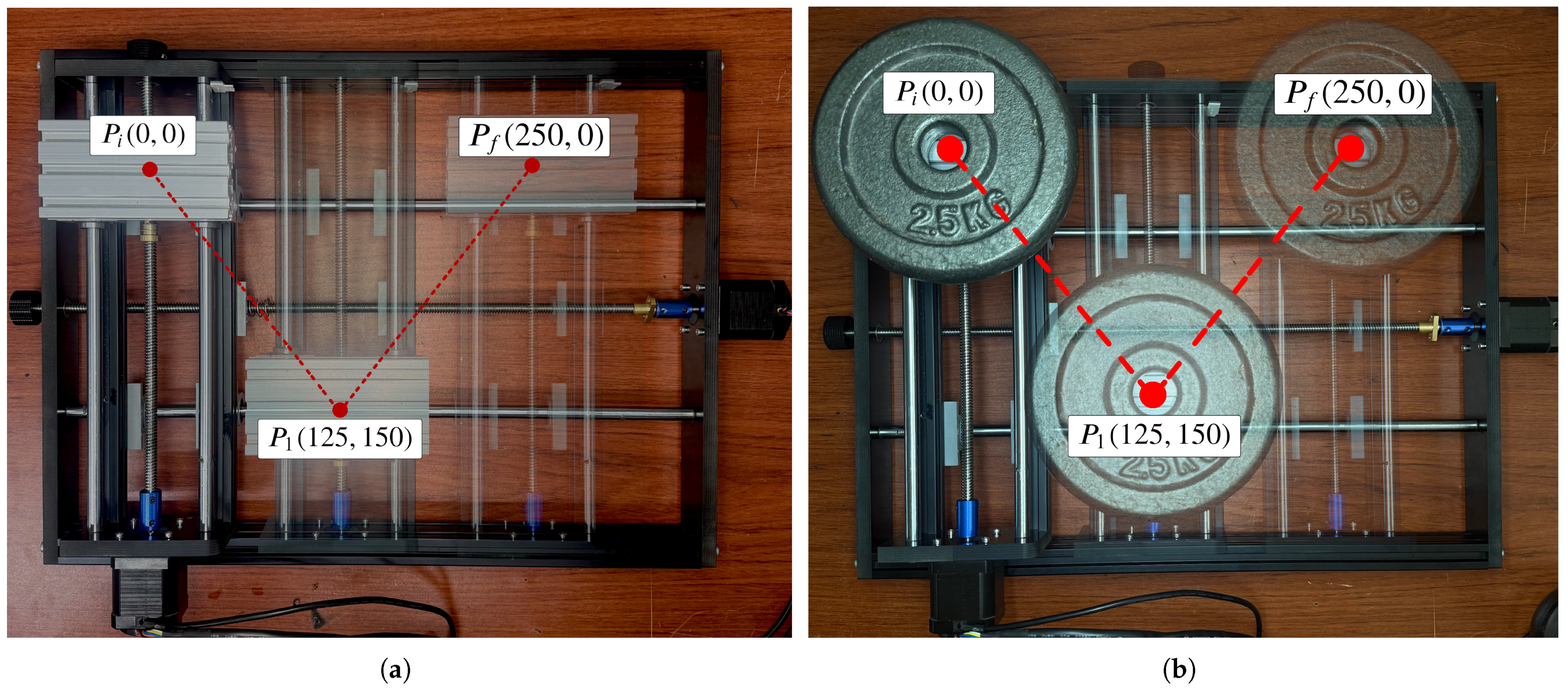
Figure 7 presents the reference trajectory used in the experimental tests to evaluate the performance of the tracking system using a trapezoidal motion profile. The trajectory is defined by three reference points: the initial point ( P i ) , the intermediate point ( P 1 ) , and the final point ( P f ) . It is important to note that the coordinates are expressed in millimeters. Figure 7a shows the system configuration operating without an external load, whereas Figure 7b illustrates the same trajectory under a loading condition of 2.5 [ kg ] . These tests allowed for the analysis of the system’s behavior and the comparison of the trajectory tracking performance under different operating conditions.
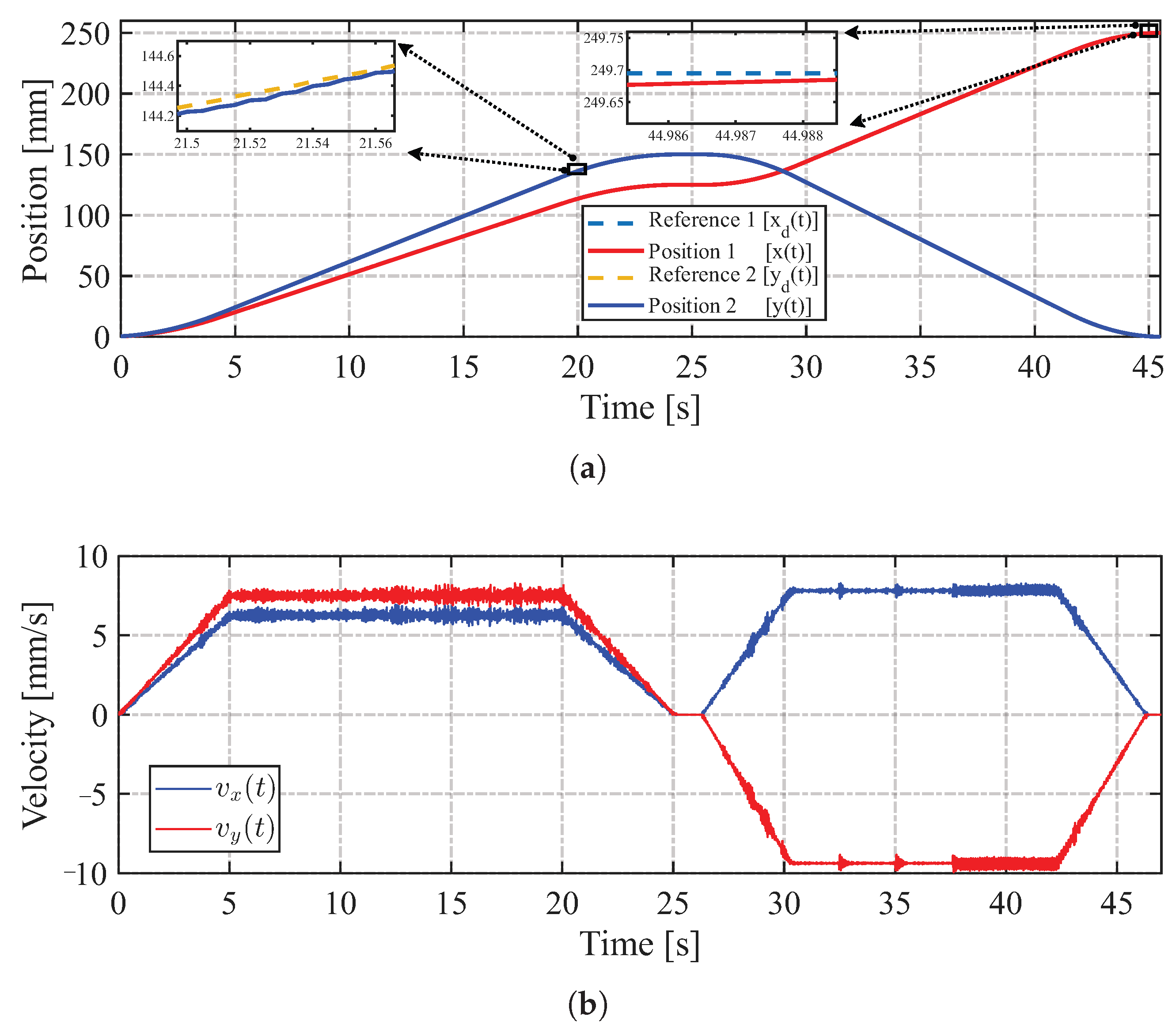
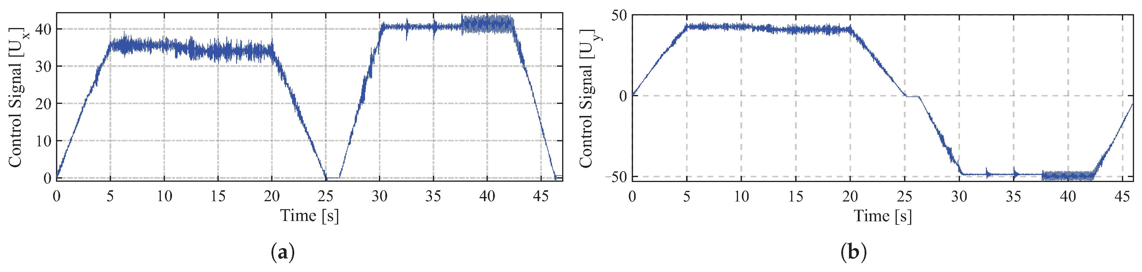
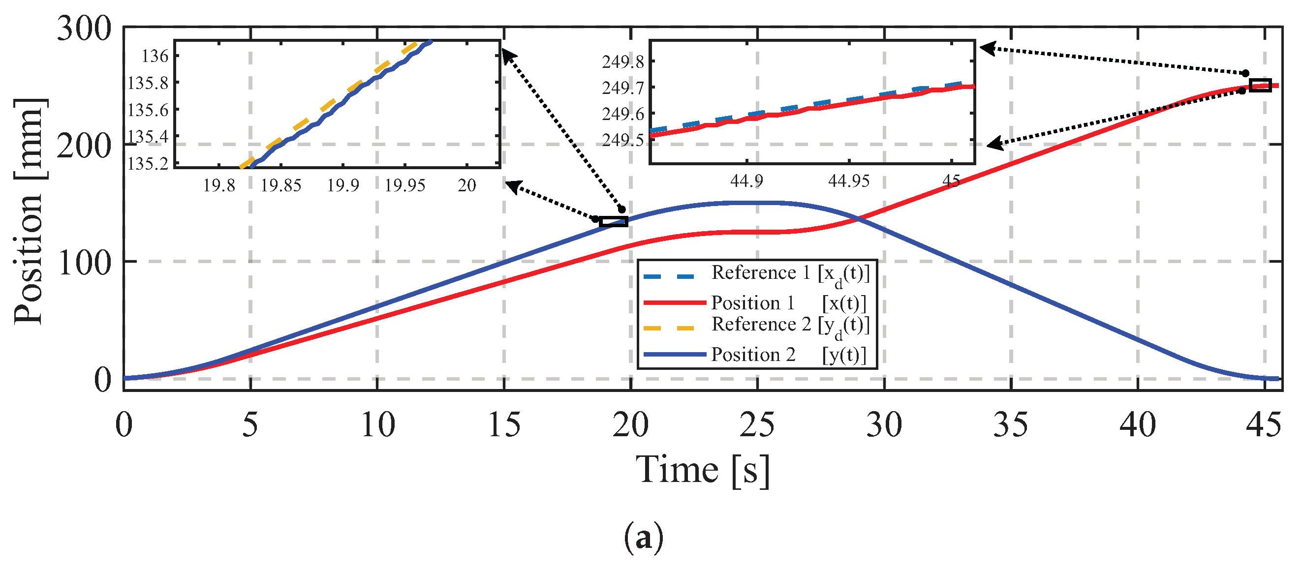
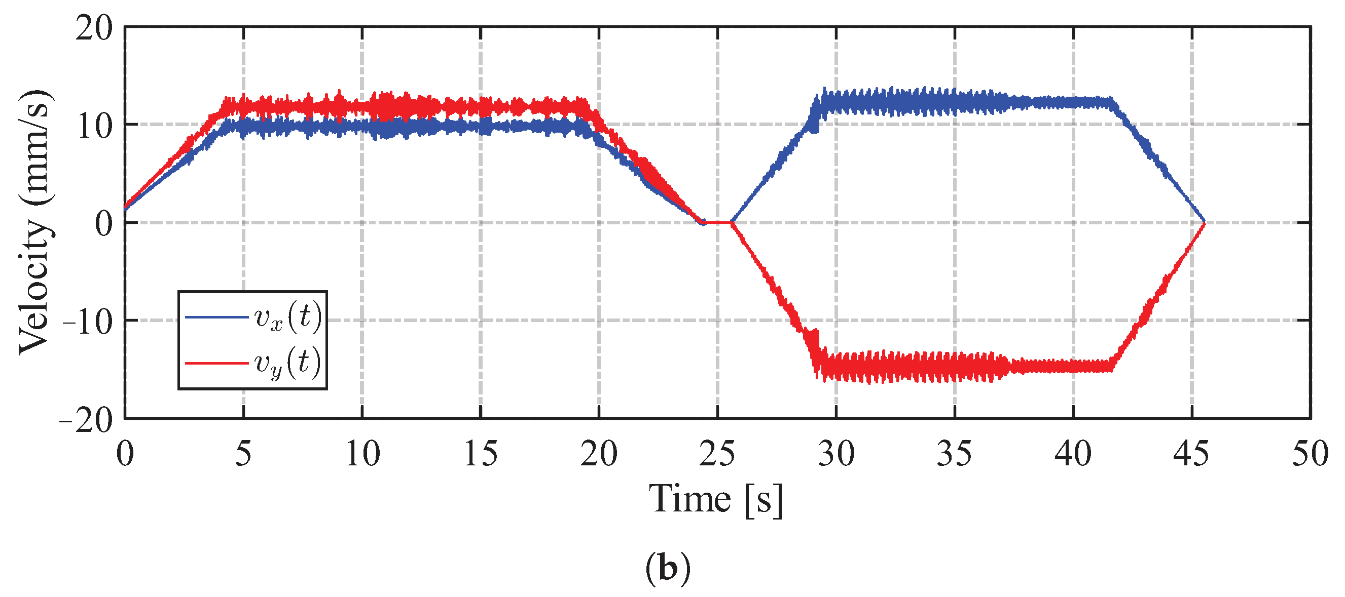
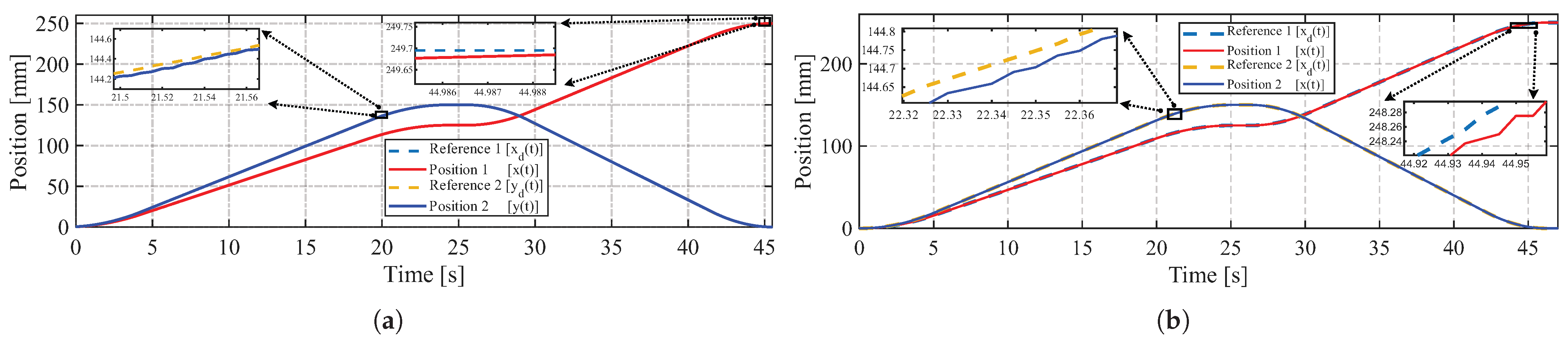
The performance of the proposed adaptive fuzzy feedforward controller was evaluated using an X–Y positioning system subjected to a multi-segment trajectory defined by three waypoints. The motion started at the initial position ( 0 [ mm ] , 0 [ mm ] ) , passed through the intermediate point ( 125 [ mm ] , 150 [ mm ] ) , and ended at the final position ( 250 [ mm ] , 0 [ mm ] ) . This trajectory was selected to assess the controller’s ability to coordinate both axes simultaneously while maintaining accurate position tracking along a nonlinear path. Figure 8a presents the position tracking performance of the generated reference motion profiles, whereas Figure 8b shows the corresponding velocity responses of the X and Y axes during trajectory execution. Finally, Figure 9a,b show the control signals applied to the X-axis and Y-axis stepper motors, respectively.
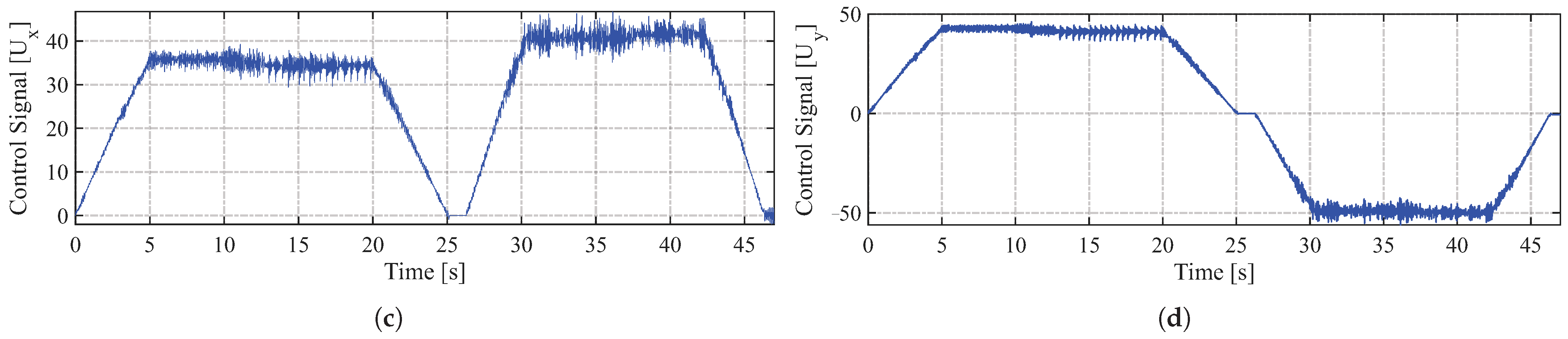
The robustness of the proposed controller was evaluated by subjecting the X–Y positioning system to external load disturbances during trajectory execution. Figure 10a,b present the position and velocity tracking responses, respectively, under loaded operating conditions. Despite the presence of external loads, the controller maintained accurate tracking performance and stable system behavior. The control signals generated for both stepper motors under external loading conditions are shown in Figure 11, illustrating the controller’s ability to compensate for disturbances while preserving coordinated motion of the X and Y axes.
Table 9 summarizes the performance metrics computed from the Euclidean tracking error under unloaded and loaded operating conditions. The results indicate that the proposed adaptive fuzzy feedforward controller maintained similar tracking performance when a 7.5 [ kg ] external load was applied to the X–Y positioning system. The RMSE increased slightly from 0.0749 [ mm ] to 0.0760 [ mm ] , while the IAE rose from 0.2556 [ mm · s ] to 0.2712 [ mm · s ] . Similarly, the ISE and ITAE values exhibited only minor variations under loaded conditions. These results demonstrate that the proposed controller effectively compensated for the effects of the external load, preserving accurate trajectory tracking and exhibiting robust performance despite the additional mechanical disturbance. Furthermore, Table 10 summarizes the performance metrics obtained for each motor during trajectory tracking under unloaded and externally loaded conditions.
For comparison purposes, the proposed adaptive fuzzy feedforward controller was experimentally evaluated against a conventional PID controller under the same trajectory-tracking conditions. Figure 12 compares the position responses obtained with both control strategies for the X–Y positioning system along the predefined trajectory. As observed, the proposed controller provides more accurate trajectory tracking, particularly during the transient segments, while maintaining smooth motion throughout the entire trajectory.
Table 11 summarizes the performance metrics computed from the Euclidean tracking error for both controllers. The proposed adaptive fuzzy feedforward controller achieved the lowest RMSE, reducing the tracking error from 0.1741 mm to 0.0749 mm , corresponding to an improvement of approximately 57%. Likewise, the IAE, ISE, and ITAE were significantly reduced compared with the conventional PID controller, indicating improved cumulative tracking accuracy, lower overall error energy, and enhanced transient performance. These results demonstrate that the proposed adaptive fuzzy feedforward controller consistently outperforms the conventional PID controller in terms of trajectory-tracking accuracy for the X–Y positioning system.

3.4. Verification of the Synchronism Preservation Condition

To verify the synchronism-preservation condition established by Equations (28) and (29), the maximum actuator-step tracking error obtained during the experimental evaluation was analyzed.
For the experimental X–Y positioning platform, the lead screw pitch was 4 mm rev , and the motion system operated with an effective resolution of 4000 steps rev . Consequently, the axis resolutions were determined as
k x = k y = 4 mm rev 4000 steps rev = 0.001 mm step .
An admissible synchronization limit of
N max = 50 [ steps ]
was adopted, which corresponds to a maximum admissible Cartesian tracking error of 0.05 [ mm ] .
According to Equation (29), the corresponding admissible Cartesian tracking region is
| e x ( t ) | < 0.05 [ mm ] , | e y ( t ) | < 0.05 [ mm ] .
The maximum Cartesian tracking error observed during the experimental tests was
| e x ( t ) | max = 0.0064 [ mm ] , | e y ( t ) | max = 0.0064 [ mm ] .
Using Equation (27), the corresponding actuator-step tracking error is given by Equation (38).
e N ( t ) = 0.0064 [ mm ] 0.001 mm step = 6.4 [ steps ] .
Substituting this value into the synchronism-preservation condition of Equation (28) yields Equation (39).
6.4 [ steps ] < 50 [ steps ] ,
confirming that the actuator-step tracking error remains inside the admissible synchronization region throughout operation. Therefore, the synchronism-preservation criterion proposed in Section 2.4 is experimentally satisfied, demonstrating that the adaptive controller maintains the tracking error within the admissible bounds required to avoid step loss.

4. Discussion

The experimental results demonstrate that the proposed adaptive fuzzy feedforward controller provides accurate trajectory tracking under different operating conditions. Compared with the conventional PID controller, the proposed strategy achieved lower values of the RMSE, IAE, ISE, and ITAE, demonstrating superior tracking accuracy and improved transient performance. Furthermore, under external loading conditions, the controller effectively adjusted the proportional, derivative, and feedforward actions according to the tracking error, step frequency, and adaptation variable, allowing the X–Y positioning system to compensate for the additional mechanical demand while preserving the coordinated motion of both axes. These results confirm the effectiveness and robustness of the proposed adaptive control strategy.
From a global perspective, the increase in RMSE from 0.0749 mm under no-load conditions to 0.0760 mm with a 7.5 kg payload is minimal despite the substantial increase in mechanical stress. Similar behavior is observed for the IAE and ITAE, which exhibit only moderate increments under loading. These results suggest that the adaptive fuzzy mechanism effectively compensates for load disturbances, preventing significant degradation of the tracking performance and maintaining the positioning error within a narrow range throughout the trajectory.
The analysis at the actuator level provides additional insight into the behavior of the proposed controller. Although both motors experienced slight increases in RMSE under the maximum payload, the accumulated absolute error remained relatively stable, indicating that the overall tracking quality was largely preserved. The more noticeable increase in ITAE suggests that the applied load mainly affected the persistence of the tracking error rather than its instantaneous magnitude, requiring a longer transient response while still achieving accurate final positioning.
To further contextualize these results, Table 12 compares the proposed strategy with representative approaches reported in the literature. Although direct quantitative comparisons should be interpreted cautiously because of differences in simulation and experimental platforms, trajectories, and evaluation protocols, several meaningful observations can be drawn. The Gaussian acceleration profile reported in [37] presents RMSE values ranging from 0.0972 mm to 0.2355 mm, whereas the proposed controller achieves a lower RMSE of 0.0749 mm under nominal conditions, indicating improved tracking precision for the evaluated X–Y positioning task. Likewise, the adaptive-weight PI-SMC strategy presented in [8] reports an IAE of 1.575 mm·s, which is considerably higher than the 0.2556 mm·s obtained by the proposed method, suggesting that the fuzzy gain adaptation effectively limits the accumulated tracking deviation throughout the motion. The control strategy reported in [38] evaluates repetitive positioning accuracy in a gantry-type mechanism driven by stepper motors along the X-, Y-, and Z-axes. In that study, a trapezoidal acceleration and deceleration profile was implemented, resulting in an average X-axis RMSE of 0.30 mm. In comparison, the proposed adaptive fuzzy feedforward controller achieved an RMSE of 0.0468 mm for X-axis tracking. Although the RMSE values were obtained under different experimental configurations and tracking tasks, the comparison provides a useful reference for positioning performance in stepper-motor-driven systems. In contrast, the present work complements this type of approach by experimentally validating the controller under multiple payload scenarios while simultaneously reporting RMSE, IAE, ISE, and ITAE. Similarly, the NAIA controller evaluated in [1] achieves RMSE values between 0.0226 mm and 0.0941 mm depending on the operating conditions, placing the proposed method within the performance range of advanced intelligent controllers while additionally demonstrating robustness against significant external loading.
Overall, the comparison indicates that the principal contribution of the proposed methodology is not merely the reduction of tracking error but the preservation of consistent performance under varying mechanical conditions. Unlike several related studies that report only nominal experiments or a limited set of performance indicators, the proposed adaptive fuzzy controller maintains low tracking errors while providing a comprehensive experimental evaluation under different payloads, supporting its suitability for precision X–Y positioning applications in which operating conditions may change during execution.
Finally, it is important to acknowledge that real word X-Y positioning systems are subject to numerous sources of physical errors that affect overall accuracy. Mechanical factors such as static and dynamic friction in the linear guides, mechanical backlash in the lead screws, as well as disturbances like stepper motor vibrations and electrical noise, contribute to position deviations. In this context, the proposed adaptive fuzzy strategy is highly advantageous. Instead of relying on exhaustive deterministic calculations for each physical imperfection, the controller helps combat the aggregate effect of these uncertainties by dynamically adjusting the gains based on tracking performance.

5. Conclusions

This paper presented an adaptive fuzzy feedforward–feedback control architecture for a stepper-motor-driven X–Y positioning system. The proposed controller combines a Takagi–Sugeno fuzzy inference mechanism with adaptive proportional, derivative, and feedforward actions whose gains are adjusted according to the tracking error, step frequency, and an auxiliary adaptation variable.
Experimental validation demonstrated the effectiveness of the proposed approach in both single-axis and multi-axis trajectory-tracking tasks. For a trapezoidal motion profile, the controller achieved accurate position and velocity tracking, with a steady-state position error of approximately 1.6 [ μ m ] . The generated control actions and step frequencies remained bounded throughout the experiments, indicating stable operation and preservation of motor synchronism.
The controller was further evaluated using a multi-segment trajectory defined by three waypoints. The experimental results showed accurate coordination of the X- and Y-axes, enabling smooth motion along a nonlinear path while maintaining low tracking errors. The Euclidean-error-based performance metrics confirmed the high tracking accuracy of the proposed strategy, yielding an RMSE of 0.0749 [ mm ] under unloaded conditions. Furthermore, comparison with a conventional PID controller demonstrated that the proposed adaptive fuzzy feedforward–feedback controller consistently achieved lower RMSE, IAE, ISE, and ITAE values, confirming its superior trajectory-tracking accuracy and transient performance.
The robustness of the controller was assessed by applying external loads of up to 7.5 [ kg ] . Despite the additional mechanical disturbance, only minor variations were observed in the Euclidean tracking metrics. The RMSE increased from 0.0749 [ mm ] to 0.0760 [ mm ] , while the IAE, ISE, and ITAE exhibited similarly small changes. The individual motor performance indices also remained within a narrow range, demonstrating the ability of the adaptive fuzzy feedforward–feedback controller to compensate for load variations while preserving tracking accuracy and system stability.
Overall, the proposed control architecture provides an effective solution for high-precision X–Y positioning systems driven by stepper motors. The combination of adaptive fuzzy gain scheduling, feedforward compensation, and synchronism-preservation analysis enables accurate trajectory tracking and robust performance under varying operating conditions, making the proposed approach suitable for embedded implementation in industrial positioning applications.
The experimental validation, demonstrating a minimal steady-state error of 1.6 [ μ m ] and robust compensation for external payloads up to 7.5 [ kg ] , confirms that the proposed approach meets the stringent demands of modern automated systems. Specifically, its ability to maintain dynamic accuracy under load variations makes it highly suitable for different operations. Concurrently, its high positioning precision and smooth trajectory execution satisfy the rigorous requirements of data acquisition instruments, offering a highly capable and efficient solution for implementation. It is worth noting that the experimental validation was conducted in a controlled laboratory environment at an ambient temperature of 23 [ C ] to minimize thermally induced errors. A detailed temperature analysis represents an important direction for future research.


Author Contributions

Conceptualization, J.R.G.-M. and J.R.R.-R.; methodology, J.R.G.-M.; software, E.G.-G., A.J.C.-E., E.V.-I. and E.E.C.-M.; validation, E.G.-G., A.J.C.-E., E.V.-I., E.E.C.-M., J.C.-S., and J.R.G.-M.; formal analysis, J.R.G.-M.; investigation, J.R.G.-M., E.E.C.-M. and J.R.R.-R.; resources, E.G.-G., A.J.C.-E., E.V.-I., E.E.C.-M., J.C.-S., J.R.R.-R. and J.R.G.-M.; data curation, J.R.G.-M. and J.R.R.-R.; writing—original draft preparation, J.R.G.-M. and J.R.R.-R.; writing—review and editing, E.G.-G., A.J.C.-E., E.V.-I., E.E.C.-M., and J.C.-S.; visualization, J.R.G.-M. and J.R.R.-R.; supervision, J.R.G.-M.; project administration, E.G.-G., A.J.C.-E., E.V.-I., E.E.C.-M., J.C.-S., J.R.R.-R. and J.R.G.-M.; funding acquisition, E.G.-G., A.J.C.-E., E.V.-I., E.E.C.-M., J.C.-S., J.R.R.-R. and J.R.G.-M. All authors have read and agreed to the published version of the manuscript.

Funding

This research received no external funding.

Data Availability Statement

The original contributions presented in this study are included in the article. Further inquiries can be directed to the corresponding author.

Acknowledgments

The authors E.G.-G., A.J.C.-E., E.V.-I. and J.R.R.-R. gratefully acknowledge the financial support provided by the Secretaría de Ciencia, Humanidades, Tecnología e Innovación (SECIHTI) through graduate scholarships awarded to the authors (CVU E.G.-G.: 483291, CVU A.J.C.-E.: 2202924, CVU E.V.-I.: 2202952, and CVU J.R.R.-R.: 2202960). The manuscript was reviewed using Grammarly Desktop (version 1.169.1.0) solely for grammatical and language correction purposes.

Conflicts of Interest

The authors declare no conflicts of interest.

Abbreviations

The following abbreviations are used in this manuscript:
PIDProportional–Integral–Derivative
UAVsUnmanned Aerial Vehicles
MPCModel Predictive Control
FAMFuzzy Associative Memory
T-STakagi–Sugeno
NRMSENormalized Root Mean Square Error
MSEMean Square Error
RMSERoot Mean Square Error
IAEIntegral of Absolute Error
ITAEIntegral of Time-weighted Absolute Error
ISEIntegral Square Error

Appendix A

This appendix provides additional information regarding the mechanical components employed in the proposed X–Y positioning platform. The purpose of this description is to improve the reproducibility of the experimental setup by specifying the main structural and transmission elements, their constituent materials, their primary mechanical functions, and representative applications in related positioning and automation systems. The selected components were chosen to provide a compact, low-cost, and mechanically rigid architecture suitable for laboratory-scale precision positioning experiments.
Table A1. Mechanical components employed in the proposed X–Y positioning platform, including their constituent materials, primary functions, and typical applications.
ComponentMaterialPrimary FunctionTypical Applications
2040 T-slot structural profilesAnodized 6063-T5 aluminum alloyMain frame of the X–Y positioning platform3D printers, desktop CNC machines, industrial automation systems, robotic structures
Structural plates and supportsPhenolic polymerMechanical joints and structural supportMechanical structures, laboratory automation equipment
Linear guide rodsChrome-plated steelLinear motion guidance3D printers, CNC machines, coordinate measuring systems, robotic mechanisms
Tr8×4 lead screwAISI 304 stainless steelConversion of rotary motion into linear displacementZ-axis drives in 3D printers, X–Y positioning tables, linear actuators
Tr8×4 lead nutBrassLinear motion transmission with low frictionLinear positioning and motion transmission systems
SCS8UU linear bearing blocksAluminum-alloy housing with internal hardened-steel ball linear bearingLow-friction linear motion along the guide rodsCNC machines, 3D printers, Cartesian robots, linear motion systems
5–8 mm rigid shaft couplingsAluminumConnection between the NEMA 17 motor shaft and the lead screwCNC machines, industrial automation equipment, stepper motor drive systems
M5 fastenersSteelMechanical assembly and fixationMechanical assemblies and industrial equipment

References

  1. Retas, Z.; Abdullah, L.; Jamaludin, Z.; Muhammad, M.S.S.; Maslan, M.N.; Zamri, R.; Kamaludin, K.N.; Rahman, A.I.A.; Zainon, M.; Salim, S.N.S.; et al. Assessment on Tracking Performance of PID, Cascade Proportional Adaptive Interaction Algorithm and Nonlinear Adaptive Interaction Algorithm Controller of XY Table Ball Screw Driven System. J. Adv. Res. Des. 2026, 141, 74–89. [Google Scholar]
  2. Fan, Y.; Fan, K.C.; Huang, Y.; Li, J. Analysis and On-Machine Measurement of Full-Field Cross-Talks of Stacked X–Y Stages. Nanomanufacturing Metrol. 2026, 9, 1. [Google Scholar] [CrossRef] [Scilit]
  3. Li, Q.; Jin, L.; Qiu, Y.; Zhang, L.; Li, Z.; Li, H. Closed-Loop Motion Control-Based Application of Stepper Motors in Laser Engraving Machines. In Proceedings of the 2025 Third International Conference on Cyber-Energy Systems and Intelligent Energy (ICCSIE), Shenyang, China, 3–5 October 2025; IEEE: Piscataway, NJ, USA, 2025; pp. 1–6. [Google Scholar]
  4. Erjun, Y.; Mingliang, H. Design of high-precision and high-reliability aircraft stepper motor drive servo control system. In Proceedings of the CSAA/IET International Conference on Aircraft Utility Systems (AUS 2020), Online, 18–21 September 2020; IET: London, UK, 2020; Volume 2020, pp. 22–27. [Google Scholar]
  5. Minh, T.V.; Anh, N.T.; Tung, T.T. Torque Measurement System Design for Step Motor 23HS30-3004S. Eng. Technol. Appl. Sci. Res. 2025, 15, 19073–19077. [Google Scholar] [CrossRef] [Scilit]
  6. Liu, M.; Yu, Y.; Cui, L.; Ji, N.; Deng, X. Research on micro-/nano-positioning system driven by a stepper motor. Actuators 2024, 13, 246. [Google Scholar] [CrossRef] [Scilit]
  7. Li, C.; Tang, S.; Yin, M.; Zhao, X.; You, H. Enhancing position tracking of hybrid stepper motors using lyapunov-based current controllers. Electronics 2025, 14, 1997. [Google Scholar] [CrossRef] [Scilit]
  8. Lixian, S.; Rahiman, W. A compound control for hybrid stepper motor based on PI and sliding mode control. IEEE Access 2024, 12, 163536–163550. [Google Scholar] [CrossRef] [Scilit]
  9. Lin, Z.; Li, H.; Zeng, T.; Wang, L.; Zhu, B.; Zhang, X.; Wang, H. Full closed-loop control of the stepper motor-driven displacement module for cross-scale assembly robot. In Proceedings of the 2025 5th International Conference on Mechanical Automation and Electronic Information Engineering (MAEIE), Ningbo, China, 27–29 November 2025; IEEE: Piscataway, NJ, USA, 2025; pp. 285–289. [Google Scholar]
  10. Jaswal, A.; Abu-Ayyad, M.; Lad, Y.; Attaluri, A. Stepper motor position control using PD and MPC algorithms embedded in programmable logic controller. IEEE Access 2025, 13, 39096–39106. [Google Scholar] [CrossRef] [Scilit]
  11. Le, H.D.; Nestorović, T. Integral Linear Quadratic Regulator Sliding Mode Control for Inverted Pendulum Actuated by Stepper Motor. Machines 2025, 13, 405. [Google Scholar] [CrossRef] [Scilit]
  12. Derouech, Y.; Mesbahi, A. Integral Sliding Mode Control and Digital Controller Design Using State Space Methods for a Hybrid Stepper Motor: Comparative Study. In Proceedings of the 2023 3rd International Conference on Innovative Research in Applied Science, Engineering and Technology (IRASET), Mohammedia, Morocco, 18–19 May 2023; IEEE: Piscataway, NJ, USA, 2023; pp. 1–6. [Google Scholar]
  13. Kazemi, S.; Gentes, S. Self-Constructing Neural Network Controllers with Adaptive Structural Learning: Application to Stepper Motor Positioning. In Proceedings of the 2025 13th International Conference on Control, Mechatronics and Automation (ICCMA), Paris, France, 24–26 November 2025; IEEE: Piscataway, NJ, USA, 2025; pp. 231–236. [Google Scholar]
  14. Kravets, P.; Novatskyi, A.; Shymkovych, V.; Rudakova, A.; Lebedenko, Y.; Rudakova, H. Neural network model for laboratory stand control system controller with parallel mechanisms. In Proceedings of the International Conference on Computer Science, Engineering and Education Applications, Warsaw, Poland, 17–19 March 2023; Springer: Berlin/Heidelberg, Germany, 2023; pp. 47–58. [Google Scholar]
  15. Babu, R.G.; Chellaswamy, C.; Geetha, T. Actor–critic learning-based adaptive fuzzy controller for stepper motor. Trans. Inst. Meas. Control 2023, 45, 2914–2932. [Google Scholar] [CrossRef] [Scilit]
  16. Zhang, M.; Xu, C.; Li, L.; Wang, Z.; Zong, X. Optimization of PID controller for stepper motor speed control system based on improved sparrow search algorithm. Proc. Inst. Mech. Eng. Part C J. Mech. Eng. Sci. 2024, 238, 9397–9411. [Google Scholar] [CrossRef] [Scilit]
  17. Zhang, Z.; Meng, X.; Kou, Y. Research step of PID control method of stepper motor based on improved fuzzy control algorithm. EAI Endorsed Trans. Scalable Inf. Syst. 2024, 11. [Google Scholar] [CrossRef] [Scilit]
  18. Xiao, L.; Liu, Y.; Zuo, Q.; Cao, M.; Kuang, W. A Fuzzy Weighted Self-Allocation Sliding Mode Controller for UAV Trajectory Tracking. J. Frankl. Inst. 2026, 363, 108418. [Google Scholar] [CrossRef] [Scilit]
  19. Rivera-Ruiz, J.R.; García-Martínez, J.R.; Martínez-Sánchez, T.; Cruz-Miguel, E.E.; Ramírez-González, L.D.; Barra-Vázquez, O.A.; Odry, Á. Takagi–Sugeno–Kang Fuzzy Inference Tracking Controller for UAV Bicopter. Symmetry 2025, 17, 759. [Google Scholar] [CrossRef] [Scilit]
  20. Zhang, W. Predefined-time fuzzy control for robotic manipulators driven by compliant actuators. Int. J. Fuzzy Syst. 2026, 28, 117–126. [Google Scholar]
  21. Pérez-Juárez, J.G.; García-Martínez, J.R.; Medina Santiago, A.; Cruz-Miguel, E.E.; Olmedo-García, L.F.; Barra-Vázquez, O.A.; Rojas-Hernández, M.A. Kinematic fuzzy logic-based controller for trajectory tracking of wheeled mobile robots in virtual environments. Symmetry 2025, 17, 301. [Google Scholar] [CrossRef] [Scilit]
  22. García-Martínez, J.R.; Rodríguez-Reséndiz, J.; Cruz-Miguel, E.E. A new seven-segment profile algorithm for an open source architecture in a hybrid electronic platform. Electronics 2019, 8, 652. [Google Scholar] [CrossRef] [Scilit]
  23. Jee, S.; Koren, Y. Adaptive fuzzy logic controller for feed drives of a CNC machine tool. Mechatronics 2004, 14, 299–326. [Google Scholar] [CrossRef] [Scilit]
  24. Olmedo-García, L.F.; García-Martínez, J.R.; Rodríguez-Reséndiz, J.; Dublan-Barragán, B.S.; Cruz-Miguel, E.E.; Barra-Vázquez, O.A. Tsukamoto fuzzy logic controller for motion control applications: Assessment of energy performance. Technologies 2025, 13, 387. [Google Scholar] [CrossRef] [Scilit]
  25. Tung, E.D.; Tomizuka, M. Feedforward Tracking Controller Design Based on the Identification of Low Frequency Dynamics. J. Dyn. Syst. Meas. Control 1993, 115, 348–356. [Google Scholar] [CrossRef] [Scilit]
  26. Li, W.; Yang, Q. Develop on feed-forward real time compensation control system for movement error in CNC machining. In Proceedings of the 2010 International Conference on Computer Application and System Modeling (ICCASM 2010), Taiyuan, China, 22–24 October 2010; IEEE: Piscataway, NJ, USA, 2010; Volume 7, pp. 234–238. [Google Scholar]
  27. Ehtiwesh, I.; Ahmed, A.; Ali, M. Design and Implementation of a Closed-Loop CNC Engraving Machine Using Arduino-Based PID Control. J. Open Hardw. 2026, 10. [Google Scholar] [CrossRef] [Scilit]
  28. Liu, S.; Yu, H.; Liu, D.; Wang, J. A feedforward–feedback control framework for disturbance rejection in multi-loop PI controlled servo actuators under varying disturbance sensing conditions. ISA Trans. 2026, 173, 577–593. [Google Scholar] [CrossRef] [Scilit] [PubMed]
  29. Tan, S.; Tang, X.; Yang, J.; Ding, H. Design of a novel two-DOF robotic active vibration suppression system based on dynamic decoupling and pose-dependent dynamics. Int. J. Robot. Res. 2026, 02783649261423559. [Google Scholar]
  30. Al-Mayyahi, A.; Ali, R.S.; Thejel, R.H. Designing driving and control circuits of four-phase variable reluctance stepper motor using fuzzy logic control. Electr. Eng. 2018, 100, 695–709. [Google Scholar] [CrossRef] [Scilit]
  31. Normanyo, E.; Agyare, O.R.; Rashid, R.A. MATLAB Implementation of Position Control of a Hybrid Stepper Motor Using Fuzzy Logic Controller. In Proceedings of the 2019 IEEE AFRICON, Accra, Ghana, 25–27 September 2019; IEEE: Piscataway, NJ, USA, 2019; pp. 1–8. [Google Scholar] [CrossRef] [Scilit]
  32. Wang, C.; Cao, D. New sensorless speed control of a hybrid stepper motor based on fuzzy sliding mode observer. Energies 2020, 13, 4939. [Google Scholar] [CrossRef] [Scilit]
  33. Khanesar, M.A.; Yan, M.; Karaca, A.; Isa, M.; Piano, S.; Branson, D. Interval Type-2 Fuzzy Logic Control of Linear Stages in Feedback-Error-Learning Structure Using Laser Interferometer. Energies 2024, 17, 3434. [Google Scholar] [CrossRef] [Scilit]
  34. Gaan, D.R.; Kumar, M.; Sudhakar, S. Real-Time Precise Position Tracking With Stepper Motor Using Frequency Modulation Based Microstepping. IEEE Trans. Ind. Appl. 2018, 54, 693–701. [Google Scholar] [CrossRef] [Scilit]
  35. Tarnini, M.Y. Fast and cheap stepper motor drive. In Proceedings of the 2015 International conference on renewable energy research and applications (ICRERA), Palermo, Italy, 22–25 November 2015; IEEE: Piscataway, NJ, USA, 2015; pp. 689–693. [Google Scholar]
  36. Góra, G.; Gac, K.; Górski, J.; Iwaniec, J. Investigating the Impact of Stepper Motor Control Strategy on the Level of Vibrations. Appl. Sci. 2026, 16, 4561. [Google Scholar] [CrossRef] [Scilit]
  37. González-Villagómez, E.; Rodríguez-Donate, C.; Mata-Chávez, R.I.; Cabal-Yepez, E.; López-Hernández, J.M.; Palillero-Sandoval, O. Novel Gaussian Acceleration Profile for Smooth Jerk-Bounded Trajectories. IEEE Access 2022, 10, 120714–120723. [Google Scholar] [CrossRef] [Scilit]
  38. Ma, H.; Ding, Y.; Cui, H.; Ji, J.; Jin, X.; Ding, T.; Wang, J. The Application of an Intelligent Agaricus bisporus-Harvesting Device Based on FES-YOLOv5s. Sensors 2025, 25, 519. [Google Scholar] [CrossRef] [Scilit] [PubMed]
Figure 1. Mechanical design of the proposed X–Y positioning platform. (a) Isometric view illustrating the overall system architecture and volumetric arrangement. (b) Front view highlighting the structural profiles, motor mounting, and transmission components. (c) Side view showing the vertical arrangement and mechanical proportions. (d) Top view depicting the spatial distribution of the linear guidance system and trapezoidal lead screws.
Automation 07 00114 g001
Figure 2. Fuzzy linguistic variables of the proposed fuzzy inference system. (a) Tracking error e ( t ) . (b) Step frequency f s t e p ( t ) . (c) Adaptation variable γ ( t ) .
Automation 07 00114 g002
Figure 3. Block diagram of the proposed adaptive fuzzy feedforward control architecture.
Automation 07 00114 g003
Figure 4. Proposed frequency-aware adaptive fuzzy feedforward control architecture for the X–Y positioning system.
Automation 07 00114 g004
Figure 5. Comparison between the measured angular position θ ( t ) and the simulated model output θ e ( t ) .
Automation 07 00114 g005
Figure 6. Experimental response of the proposed adaptive fuzzy feedforward controller for a stepper motor with a position reference of 16 [ mm ] : (a) Position tracking; (b) velocity tracking; (c) control signal; (d) step frequency.
Automation 07 00114 g006
Figure 7. Reference trajectory used in the experimental evaluation, where the coordinates are expressed in [ mm ] : (a) System without external load and (b) system with an applied load of 2.5 [ kg ] .
Automation 07 00114 g007
Figure 8. Experimental response of the proposed adaptive fuzzy feedforward controller for the X–Y positioning system along a trajectory defined by the points ( 0 [ mm ] , 0 [ mm ] ) , ( 125 [ mm ] , 150 [ mm ] ) , and ( 250 [ mm ] , 0 [ mm ] ) without external load. (a) Position tracking. (b) Velocity tracking.
Automation 07 00114 g008
Figure 9. Control signals of the X–Y positioning system during trajectory tracking: (a) X-axis stepper motor. (b) Y-axis stepper motor.
Automation 07 00114 g009
Figure 10. Experimental response of the proposed adaptive fuzzy feedforward controller for the X–Y positioning system along a trajectory defined by the points ( 0 [ mm ] , 0 [ mm ] ) , ( 125 [ mm ] , 150 [ mm ] ) , and ( 250 [ mm ] , 0 [ mm ] ) with an applied external load of 7.5 [ kg ] . (a) Position tracking. (b) Velocity tracking.
Automation 07 00114 g010aAutomation 07 00114 g010b
Figure 11. Control signals of the X–Y positioning system during trajectory tracking with an applied external load of 7.5 [ kg ] : (a) X-axis stepper motor. (b) Y-axis stepper motor.
Automation 07 00114 g011
Figure 12. Experimental response of the X–Y positioning system along a trajectory defined by the points ( 0 [ mm ] , 0 [ mm ] ) , ( 125 [ mm ] , 150 [ mm ] ) , and ( 250 [ mm ] , 0 [ mm ] ) . (a) Adaptive fuzzy feedforward controller. (b) PID controller.
Automation 07 00114 g012
Table 1. Parameters of the fuzzy linguistic variables for e ( t ) .
Linguistic Variable x i L x i C x i R
Negative−2.0−1.00.0
Zero0.50.00.5
Positive0.01.02.0
Table 2. Parameters of the fuzzy linguistic variables for f s t e p ( t ) .
Linguistic Variable x i L x i C x i R
Low0.00.02500.0
Medium0.02500.05000.0
High2500.05000.05000.0
Table 3. Parameters of the fuzzy linguistic variables for γ ( t ) .
Linguistic Variable x i L x i C x i R
Low0.00.00.15
Medium0.00.150.30
High0.150.300.30
Table 4. FAM for low γ ( t ) .
Tracking ErrorLow FrequencyMedium FrequencyHigh Frequency
Low ( 0.95 , 0.95 , 0.90 ) ( 0.95 , 1.00 , 0.95 ) ( 0.90 , 1.10 , 1.00 )
Medium ( 1.05 , 1.00 , 1.00 ) ( 1.10 , 1.05 , 1.10 ) ( 1.00 , 1.15 , 1.10 )
High ( 1.20 , 1.15 , 1.15 ) ( 1.18 , 1.25 , 1.20 ) ( 1.10 , 1.35 , 1.25 )
Table 5. FAM for medium γ ( t ) .
Tracking ErrorLow FrequencyMedium FrequencyHigh Frequency
Low ( 1.00 , 1.05 , 1.15 ) ( 1.00 , 1.10 , 1.20 ) ( 0.95 , 1.20 , 1.25 )
Medium ( 1.10 , 1.10 , 1.25 ) ( 1.15 , 1.15 , 1.30 ) ( 1.05 , 1.25 , 1.35 )
High ( 1.20 , 1.20 , 1.35 ) ( 1.25 , 1.30 , 1.40 ) ( 1.15 , 1.40 , 1.45 )
Table 6. FAM for high γ ( t ) .
Tracking ErrorLow FrequencyMedium FrequencyHigh Frequency
Low ( 1.05 , 1.15 , 1.35 ) ( 1.00 , 1.25 , 1.40 ) ( 0.95 , 1.35 , 1.45 )
Medium ( 1.15 , 1.25 , 1.45 ) ( 1.20 , 1.30 , 1.50 ) ( 1.10 , 1.40 , 1.55 )
High ( 1.25 , 1.35 , 1.60 ) ( 1.30 , 1.45 , 1.65 ) ( 1.20 , 1.55 , 1.70 )
Table 7. Adaptive controller parameters and coefficient ranges.
ParameterDescriptionValue/Range
α K p Proportional adaptation coefficient [ 0.90 , 1.30 ]
α K d Derivative adaptation coefficient [ 0.95 , 1.55 ]
α f f Feedforward adaptation coefficient [ 0.90 , 1.70 ]
k f f Nominal feedforward gain 1.5
K t Motor torque constant 0.08
k e Dynamic-effort indicator scaling factor 0.05
k p Proportional Gain300
k d Derivative Gain 15.2
Table 8. Key parameters of the X–Y positioning system.
ParameterDescriptionValue
Lead screw pitchLinear displacement per revolution 4 mm rev
Supply voltageStepper motor supply voltage 24 [ V ]
Sampling timeControl sampling period 5 [ ms ]
MicrosteppingDriver microstepping resolution 1 / 8 [ step ]
Full-step angleMotor step angle 1.8 [ ° ]
Steps per revolutionMotor resolution 200 steps rev
Table 9. Performance metrics computed from the Euclidean tracking error for the X–Y positioning system.
Load [kg]RMSE [mm]IAE [mm·s] ISE [mm2·s] ITAE [mm·s2]
00.07493.10610.2556141.4536
7.50.07603.22920.2712151.7711
Table 10. Performance indices of both stepper motors under different load conditions.
Motor 1
Load [kg]MSE [mm2]RMSE [mm]IAE [mm·s]ISE [mm2·s]ITAE [mm·s2]
0.00.00220.04681.97090.103386.3084
2.50.00260.05172.04430.118390.5199
7.50.00290.05382.04110.1228104.5657
Motor 2
Load [kg]MSE [mm2]RMSE [mm]IAE [mm·s]ISE [mm2·s]ITAE [mm·s2]
0.00.00320.05682.38890.152092.7577
2.50.00390.06282.47760.174092.7579
7.50.00420.06522.47280.1801112.4254
Table 11. Performance metrics computed from the Euclidean tracking error for the X–Y positioning system.
ControllerRMSE [mm]IAE [mm·s]ISE [mm2·s]ITAE [mm·s2]
Adaptive Fuzzy0.07493.10610.2556141.4536
PID0.17417.76561.4775378.6494
Table 12. Performance comparison with different control strategies.
ReferencesControl StrategyRMSE [mm]IAE [mm·s]ISE [mm2·s]ITAE [mm·s2]
Proposed methodAdaptive fuzzy control0.07490.25563.1061141.4536
[38]S-curve stepper motor drive for X-Y gantry positioning stage0.30
[8]Adaptive-weight PI-SMC composite control1.575
[1]NAIA controller0.0226–0.0941
[37]Gaussian acceleration profile0.0972–0.2355
Disclaimer/Publisher’s Note: The statements, opinions and data contained in all publications are solely those of the individual author(s) and contributor(s) and not of MDPI and/or the editor(s). MDPI and/or the editor(s) disclaim responsibility for any injury to people or property resulting from any ideas, methods, instructions or products referred to in the content.