1. Introduction
A drone, also known as an unmanned aerial vehicle (UAV), is an aircraft that can fly without the assistance of a human pilot. Drones can be remotely controlled by a pilot on the ground or programmed to fly autonomously using pre-programmed waypoints and instructions. Drones range in size and shape from small handheld models to large commercial drones used for industrial purposes. They are outfitted with sensors and cameras that allow them to capture high-quality photos and videos from the air, and they can also be used for a variety of other tasks, such as land surveying, infrastructure inspection, package delivery, and even emergency medical services. Drones have grown in popularity in recent years due to their versatility, ease of use, and low cost. They have the potential to revolutionize many industries and are expected to play a growing role in transportation, logistics, and many other fields in the future. Drone path planning is the act of identifying the best route or path for a drone to take to reach its destination or fulfill a specified mission. Path planning employs algorithms and sensors to maneuver the drone around the surroundings while avoiding obstacles and keeping on course. The path planning procedure normally begins with identifying the drone’s beginning and ending points, as well as any intermediate waypoints that it must reach. The planner then develops a path that minimizes the time, energy, or distance required to complete the objective while considering any environmental limits or safety concerns. Drone path planning must take various things into account, such as the drone’s capabilities, the area in which it will operate, and the mission objectives. For example, if the drone is surveying a big region, the path planner may need to optimize the path to cover the entire area effectively while avoiding obstacles such as buildings, trees, or power lines. Overall, path planning is an important component of drone operation since it ensures that the drone can navigate safely and effectively to its intended goals [
1].
Because of the nature of their operation in airspace, drone navigation involves several challenges [
2], including object avoidance, localization, GPS interference, weather conditions, and hardware interfacing. Drone navigation involves careful planning, reliable sensors, and sophisticated algorithms to overcome the challenges of flying in the sky. As technology progresses, we may see more advanced navigation systems that can overcome these issues and allow drones to operate safely and efficiently in a range of environments [
3]. There are numerous methods available for drone navigation, including Dijkstra’s Algorithm [
4], the A* Algorithm [
5], a Rapidly Exploring Random Tree Algorithm [
6,
7], Graph-based Algorithms [
8], Artificial Potential Fields [
9], Genetic Algorithms [
10], the Dynamic-Window Approach [
11], Ant Colony Optimization [
12], Particle Swarm Optimization [
13], Simulated Annealing [
14], the Harmony Search Algorithm [
15], a Probabilistic Roadmap [
16], the Visibility Graph Algorithm [
17], Model Predictive Control [
18], Gradient-Based Motion Planning [
19], Differential Evolution [
20], Artificial Bee Colony [
21], the Cuckoo search Algorithm [
22], the Firefly Algorithm [
23], and the Mayfly Algorithm. Different bio-inspired algorithms, such as the Mayfly and Firefly algorithms, have primarily focused on 2D navigation problems. These navigation algorithms are computer programs that enable drones to navigate independently. However, with the increasing complexity of real-world environments, there has been a growing demand for 3D navigation approaches to allow drones to operate more efficiently in three-dimensional spaces, such as urban areas, indoor environments, and densely populated regions.
The use of Riemannian manifolds [
24] in the field of robotics has become an area of increasing interest in recent years [
25]. Riemannian manifolds provide a powerful mathematical framework for analyzing and controlling the motion of drones, which can enable them to perform complex tasks such as surveillance, delivery, and search and rescue operations. Firstly, Riemannian manifolds are a type of geometric space used to describe curved surfaces. In drone navigation, Riemannian manifolds are often used to represent the configuration space of the drone, which is the set of all possible configurations that the drone can reach. By using Riemannian manifolds, we can analyze the motion of the drone as it moves through this configuration space and determine the optimal path for the drone to reach a desired goal [
26]. One of the key applications of Riemannian manifolds in drone navigation is path planning. Path planning is the process of determining a sequence of motions that will enable a drone to move from its current state to a desired goal state while avoiding obstacles and minimizing the cost of the motion. Riemannian manifolds provide a powerful framework for path planning by enabling us to define a cost function on the configuration space and optimize this cost function using Riemannian optimization techniques [
27]. Several recent research papers have explored the use of Riemannian manifolds in the field of aerial navigation. For example, Chahrour et al. [
28] contributed significantly to the field of signal processing by exploring the application of Riemannian geometry in the context of drone detection. By demonstrating the superiority of Riemannian-based methods over traditional techniques, the study opens new possibilities for enhancing drone surveillance, security, and remote sensing systems. Beik-Mohammadi et al. [
29] presented an innovative approach to equip robots with the ability to learn and adapt motion skills using a Riemannian manifold. The utilization of geodesics as natural motion skills enables efficient planning and obstacle avoidance while also empowering the robot to generate novel movements in unexplored scenarios. This advancement holds promise for enhancing the capabilities of robots in real-world settings, paving the way for more seamless human–robot collaboration in diverse and dynamic environments. Biess et al. [
30] presented a robotics system focusing on anthropomorphic hands. The researchers transformed the dimension and basis of the anthropomorphic hand structure into the Riemannian metric. This transformation allowed them to apply manifold classification to the symmetric and asymmetric patterns of particle positions. The use of the Riemannian metric in the context of anthropomorphic hands provided a novel approach to capturing the intricate movements and configurations of the hand. By leveraging the manifold application, the system was able to effectively classify and analyze both symmetric and asymmetric patterns of particle positions within the hand structure. Jaquier et al. [
31] developed geometry-aware Bayesian optimization for robotics. The researchers introduced techniques to compute geometry-aware kernels on different Riemannian manifolds commonly found in robotic applications. An examination of the simplification of general expressions for Matérn kernels using stochastic partial differential equations on these manifolds resulted in explicit formulas for geometry-aware kernels. The derived formulas provide practitioners with practical tools to apply geometry-aware Bayesian optimization in novel and diverse settings. This enables roboticists to consider the underlying geometry of the robotic system, leading to more efficient and effective optimization strategies.
There are several papers in the existing literature on the path planning of drones using Riemannian manifolds for indoor environments, but these works are computationally intensive and may not be scalable for large indoor environments with complex layouts. The previous technique must be updated to handle larger situations with an acceptable level of accuracy. Many existing works are intended for offline planning and may not be appropriate for real-time path planning. Algorithms that can generate pathways in real time must be modified. Most of the current literature on Riemannian manifolds deals with static obstacles; hence, the performance of Riemannaian manifolds need to be tested in indoor environment for dynamic obstacles. It has also been found that many Riemannian manifold-based studies are not compared to a pre-existing algorithm to compare performance. Hence, this study presents the fastest and most efficient navigating approach for drones in an interior setting with static and dynamic environments by exploiting the Riemannian manifold. In addition, this work performs real-time path planning of drones in an uncertain environment by comparing the existing relevant literature. Einstein’s general theory of relativity is based on Riemannian geometry. The theory of gravity is simplified with the Riemannian metric by transforming n-dimensional parameters into two-dimensional ones. The use of Riemannian manifolds makes it feasible to measure space–time curvature and massive objects. Riemannian geometry serves as a revolutionary tool for designing efficient and compact path-planning algorithms, utilizing the characteristics of curvature and manifolds. Key advantages in robot navigation, such as fast obstacle avoidance and shortest path selection, are achieved through the Riemannian metric approach [
32]. Other applications of Riemannian geometry include statistical data-based robot navigation, optimal path planning algorithms, and machine learning-based robot navigation [
33].
This paper is structured as follows:
Section 2 presents the mathematical framework of Riemannian manifolds as it applies to drone path planning.
Section 3 details the simulation and experimental evaluation of the proposed method within an indoor setting, with findings and discussion provided in
Section 4. Lastly,
Section 5 concludes this study and outlines potential future research directions.
2. Riemannian Manifolds for Path Planning of Drone
This paper presents a novel approach to achieve the fastest and most efficient navigating strategy for drones in indoor environments, leveraging the power of Riemannian manifolds. Riemannian manifolds are utilized in robotics and control theory to model robot configuration spaces, which are often non-Euclidean due to motion constraints. By defining a metric tensor on the configuration space, essential geometric properties like distance, curvature, and geodesics can be established. These notions play a crucial role in robot motion planning and control on curved surfaces. The use of Riemannian manifolds offers several advantages for drone navigation. Firstly, they can capture the inherent curvature and topology of complex environments, making them ideal for modeling intricate settings. Moreover, the geometry of Riemannian manifolds remains invariant under coordinate transformations, ensuring robustness in path-planning algorithms, even when the drone’s orientation changes during the mission. Another significant benefit is the ability to express optimization problems with geometric constraints, facilitating the development of path-planning algorithms that consider complex environments. Riemannian manifolds also introduce the concept of parallel transport, which enables vectors or frames to be carried along a path while preserving their direction. This feature proves valuable in developing obstacle avoidance algorithms, where the drone needs to maintain a specific orientation while avoiding obstacles. Furthermore, Riemannian manifolds provide a strong foundation for constructing feedback control algorithms based on environment geometry. This is essential in scenarios where precise path-following or orientation control is required, such as navigating along a desired path while avoiding obstacles. The technical introduction to path planning of drones using a Riemannian manifold is given as follows.
The proposed drone is three-dimensional (3D), and it is designed to achieve various objectives in the path planning of the drone. As a 3D study, it is closely related to topology, which provides the necessary 3D variants. The drone’s navigation system incorporates the characteristics of topological data analysis on Riemannian manifolds. It is a subdomain of topology, which exhibits dual characteristics over manifolds, namely spherical and hyperbolic. These dual characteristics are effectively applied in the proposed drone’s navigation system. The drone’s path planning algorithm is designed to interact with uncertain environments where obstacles are present in different positions. These positions can either be randomly distributed or follow specific patterns, leading to two distinct classes, i.e., discrete for random positions and continuous for patterns. The drone’s navigation strategy is driven by the classification of obstacle positions. By following the spherical and hyperbolic duality-based path planning algorithm, the drone efficiently navigates through uncertain environments. This duality decision allows for fast navigation, as the path planning is based on classified positions of obstacles, enabling compact decision making instead of individual vertex-by-vertex decisions. Furthermore, the efficiency advantage is achieved through the utilization of Ricci flow curvature, which is a defining characteristic of T3DRMs. Some applications of T3DRMs include studying space through its structure, dimensions, and gravitation, designing spacecraft-robot hybrids for generating automatic decisions, creating compact satellites using topological transformation, developing drones for medical surgery that work with 3D data based on manifolds, and producing micro–macro drones that utilize Riemannian metrics for diagnosis. The drone’s navigation is transformed into a topological data analysis of the Riemannian manifolds’ curvatures, and as a result, the drone automatically accelerates without encountering any obstacle challenges. The acceleration controller relies on the spherical and hyperbolic curvature over the Ricci flow curvature, ensuring the drone’s efficient navigation by following the curvature. The terms required in the mathematical modeling are explained below.
Topology: A topological space is an ordered pair , where X is a non-empty set and T is a subset of X that satisfies the following properties:
;
If then ;
If then .
The collection is referred to as a topology acting on X. The elements of T are called the open sets.
- 2
Topological Data Analysis on Riemannian Manifolds: where M is a real and smooth manifold, and is the positive definite inner product on the tangent space at each point p.
- 3
Manifold: A topological space is said to be a manifold if there exists a locally resembling Euclidean space at each point, e.g., circle, sphere, parabola, hyperbola, or other curves.
- 4
Ricci Flow Equation: where R is a Riemannian metric defined by
- 5
Riemannian Matrix: A Riemannian matric
on the smooth manifold
M is a smooth family of inner products on the tangent spaces of M. Its bilinear form on
,
is defined by
We next consider the function
where the vector fields
are given by
M, also Riemannian manifold is defined as a pair
, where
M is a differentiable manifold and
g is a Riemannian metric on
M.
Drone navigation follows the manifold characteristics classified into linear, spherical, and hyperbolic. Linear navigation refers to 2D; thus, its manifolds have a constant value. In the linear trajectory, the drone projects the goal using the Euclidean metric. Three-dimensional navigation exhibits both spherical and hyperbolic characteristics depending on the axioms of obstacle environments (discrete, continuous, and mixed), which is demonstrated as follows:
Let
be the drone,
be the goal and
be the finite set of obstacles in the three-dimensional space.
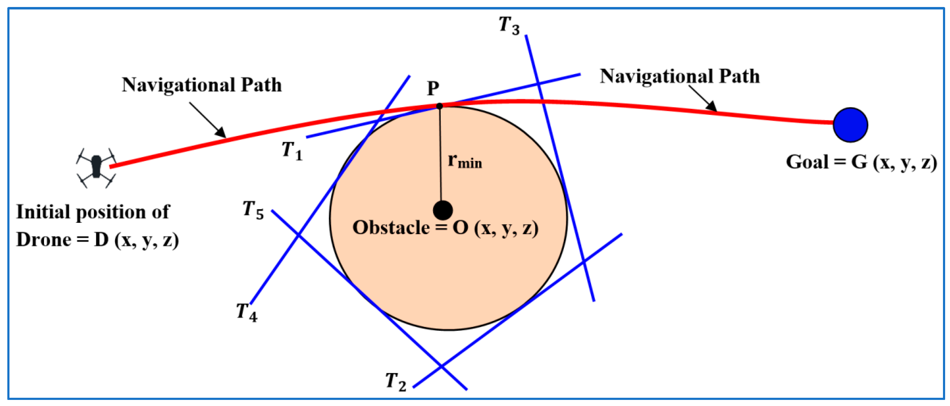
D has a sensor for identifying the obstacles and measuring the distance from the drone to the obstacle. Thus, the challenge exists to reach a goal through optimal path planning. The drone’s spherical navigation helps avoid discrete obstacles. Consider a sphere with a center (o) and radius (r) defined by
. There is a set of tangents of a sphere. The drone selects these tangents as the navigation path DP. At point P, the drone measures the distance using sensor PG and reaches goal G. The drone follows Equation (1) for this optimal navigation.
Figure 1 represents the trajectory planning through the spherical navigation:
The optimal path planning comprises the speed of the drone and the fast avoidance of obstacles. This objective is achieved by Hamilton’s Ricci flow (HRF) [
34]. HRF is an observation of the 3D transformation, e.g., from a sphere into a cylinder and vice versa. This provides a set of options to select the optimal structure, and its application appears in drone navigation. Next, Hamilton’s Ricci flow is defined.
where a Ricci curvature of the metric with respect to time
t is denoted as
and its solution is
where
is the initial radius of the sphere’s center ‘
r’. For the hyperbolic n-space
, the Ricci flow can be simplified to the ordinary differential equation (ODE)
Then, its solution is given as
The general solution is
where
The parameter of the left-hand side defines the velocity of the drone, and the right-hand side defines the three-dimensional manifolds. The drone (
D) navigates towards the goal (
G), and if there is no obstacle, then
D reaches
G. Mathematically, it can be said that
D and
R are simultaneous. If there is any obstacle, then
D avoids it by measuring the distance by metric
. It treats the obstacle as the center and the radius
r of the sphere. On the sphere, there exists a finite set of tangents
. The drone selects the tangent with minimum distance. By following this tangent, the drone reaches the surface of the sphere, and, hence, obstacles are avoided. If there are more such obstacles, then the drone follows the same process to avoid these. The topological navigation is presented in
Figure 2 based on hyperbolic geometry. There are a finite number of obstacles referred to as continuous obstacles. When applying the spherical navigation method, n spheres and n tangents will result from the n obstacles, making efficient navigation impossible. The selection of optimal tangents is challenging. Hyperbolic navigation will be feasible and efficient in this case. The drone selects point P in the hyperbola and follows the path DP for optimal navigation.
The next navigation will be based on the path PG. The curvature exists in the environment contained with discrete and continuous obstacles. This is called the hyperbolic navigation. This hyperbolic navigation is described as follows:
Hyperbolic Navigation: If the distribution of obstacles is continuous, then the continuous distribution function-based hyperbolic manifolds exist. There is no obstacle in the path PG. Thus, the drone reaches goal G. The transformation from a sphere into a hyperbola and vice versa by HRF follows the following hyperbolic navigation:
The existing obstacles are classified into two classes: single obstacles and multiple obstacles, with both having discrete, continuous, and mixed distribution functions. The discrete distribution of obstacles is observed in a spherical trajectory, and the continuous distribution of obstacles follows the principles of hyperbolic manifolds. However, the mixed (discrete and continuous) distribution of obstacles follows the tangent line axioms, which implies that a tangent line simultaneously separates the trajectory for spherical and hyperbolic navigation. The single obstacle is avoided by tangent sequences. If multiple obstacles exist, then by following the hyperbolic navigation with Equations (3) and (4), optimal path planning is generated. Let the displacement of the drone be
x; then, the velocity will be
and the acceleration will be
The direction of the drone follows the tangent line, but the displacement towards the tangent line follows the following rules as shown in
Table 1.
Where denotes a set of non-zero real positive numbers, and denotes a set of non-zero negative real numbers. The drone follows the direction obtained in the pair. If the pair is , then the drone will move in a front direction because this basis provides a linear combination with coefficients expressed as positive real numbers. If the pair is , then the drone will move in a backward direction because this provides a linear combination with coefficients expressed as negative real numbers. If the first coordinate is a positive real number and the second one is a negative real number , then the drone will move towards the left. The drone’s upward direction is represented by the coordinates ; the second coordinate is zero, resulting in linear independence with the non-zero positive real number coefficient in the first coordinate. If the first coordinate is zero, then linear independence also exists with the second coordinate’s non-zero coefficient. This will ensure that the drone moves in a downward direction.
The volume of the sphere plays a crucial role in controlling the speed of the drone as it is directly proportional to the volume of the sphere. The volume of the sphere is V, and its normalized (volume-preserving) Ricci flow equation is presented by Equation (6).
where
is a topological space with n-manifolds,
g is a Riemannian metric,
is the Ricci Tensor, and
R is the scalar curvature. For three-manifolds,
then (6) becomes
In
Table 2, the first row displays the maximum speed of the drone using the second-order partial derivative and exhibits the negative values that occur when the specified input of the first-order partial derivative is applied. The drone defines its minimum speed as the point at which the first-order partial derivative is zero, and the second-order partial derivative is positive. The speed of the drone will be considered constant when the speed command is received. Otherwise, the speed is not specified by either zero or alternate values.
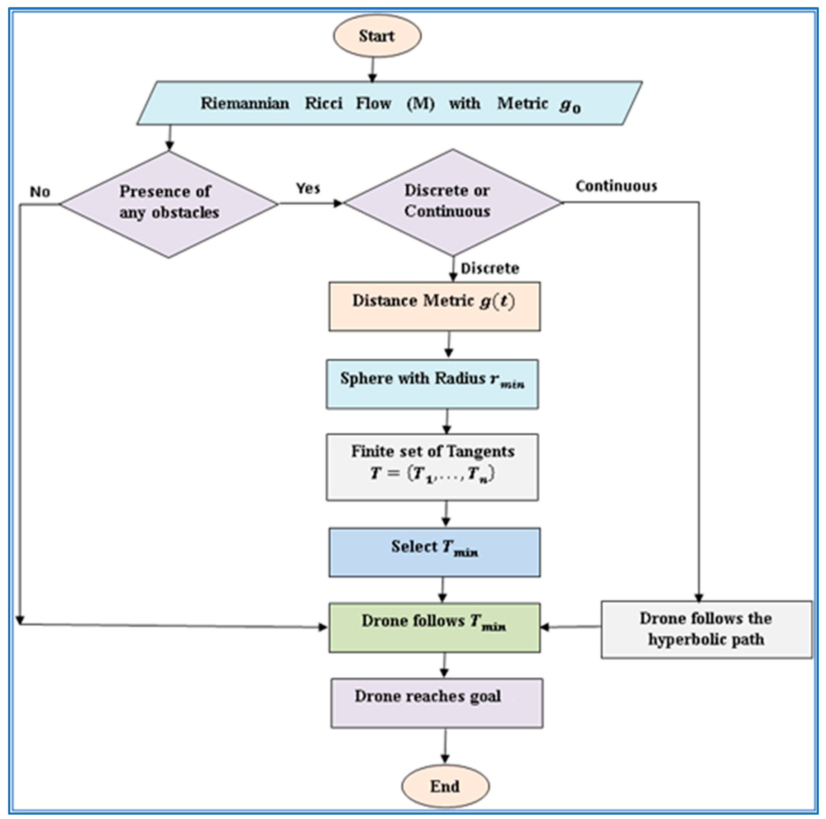
In this work, minimizing the computational time is the prime objective concerning path planning from the initial position to the final position, taking into account various constraints and environmental factors. Factors such as the complexity of the environment, the number of obstacles, the position of an obstacle, the dimensionality of search space, and computational power are considered for obtaining an optimal path with less computational time as described in Algorithm 1. By balancing the trade-off between speed and path optimality, effective path planning algorithms aim to minimize this time while maintaining safety and adherence to mission criteria, as illustrated in the flow chart in
Figure 3. The complete pseudocode is described in Algorithm 2.
| Algorithm 1: Riemannian manifolds computational time algorithm |
| 1. Drone starts navigating in the environment and time starts. |
| 2. |
| If |
|
| Then, |
|
| If |
|
| Then, |
|
| 3. Total computational time = Equation (7) + … … … + Equation (7). |
| 4. |
| 5. Path completed and complete time is recorded. |
| Algorithm 2: Pseudocode |
| 1. Drone starts. |
| 2. Riemannian Ricci flow M with metric g0. |
| 3. If any obstacle: |
| No; go to (12). |
| Yes; |
| if discrete, then go to (4). |
| If continuous, then go to (10). |
| 4. Distance metric g(t). |
| 5. Consider a sphere with center (obstacle) and radius (rmin). |
| 6. Finite set of tangents T = {T1, …, Tn}. |
| 7. Select (Tmin). |
| 8. Drone follows (Tmin, go to (3)). |
| 9. An obstacle is avoided. |
| 10. If multiple objects exist, |
| then, drone follows the hyperbolic path through
and its velocity is set by . |
| 11. Go to (3). |
| 12. Drone reaches goal. |
| 13. Drone stops. |
3. Simulation and Experimental Analysis
In this simulation study, we evaluated the performance of a T3DRM to solve path planning optimization problems for drones in static environments. The path planning approach was designed with the main objective of achieving optimal path planning from the drone’s initial position to a target destination while also ensuring path safety through obstacle avoidance. Visualization and statistical analysis of the simulation results were tested using MATLAB R2022b software. The programming for drone navigation was conducted in a 2D rectangular space measuring 600 cm by 600 cm while considering multiple static obstacles with different shapes and orientations. An assessment of drone control parameters when encountering obstacles was conducted through simulation analysis. By simulating various obstacle avoidance scenarios, researchers can assess how different control parameters impact the drone’s performance, and this allows for informed decision making when selecting optical parameter values for real-time experimentations. Altering the parameters of the T3DRM provides valuable insights into its effectiveness in path planning and obstacle avoidance. The drone parameters, such as position control, altitude control, and velocity control, are shown in
Table 3, with specified ranges for
(Proportional Gain),
(Derivative Gain), and
(Integral Gain). In this simulation study, these control parameters were carefully adjusted to ensure stable and responsive flight dynamics. Position control used
for quick adjustments,
for correcting accumulated errors, and
for minimizing oscillations. Altitude control relied on
to maintain the desired height,
ki to correct long-term deviations, and
to smooth vertical transitions. Velocity control involved
for rapid speed adjustments,
for consistent velocity tracking, and
for dampening abrupt changes. By varying these gains within their specified ranges, the simulation identified optimal settings that achieved precise and reliable control, mirroring real-world flight conditions and enhancing the drone’s overall performance.
A specially designed drone with six well-placed infrared sensors was used for the real-time analysis as shown in
Appendix A. This allowed for obstacle recognition and avoidance within a 2 to 100 cm range. A GPS sensor also made sure the drone stayed stable and oriented while in flight. Four blades on the drone provided thrust for flying and maneuverability. An onboard minicomputer handled operations, ran flight control algorithms, and processed sensor data. Pitch, roll, throttle, and yaw were basic motions that allowed the drone to perform a variety of orientations and maneuvers. The drone’s navigation in a real-time interior environment with well-placed obstacles is shown graphically in
Figure 4a,b. When there were no obstacles in the way, the drone moved on its own and did not need the T3DRM-based decision system to guide it toward its target, as shown in
Figure 4a. On the other hand, this system was activated when obstacles were identified, ensuring that the drone’s navigation was effectively and safely planned around them. This demo took place in a small area with obstacles placed to meet certain needs, which effectively highlighted the drone’s versatility in real-world situations. The drone’s navigation path from its original starting point to its intended destination is shown in
Figure 4. This image demonstrates how the drone navigated its surroundings on its own, intelligently avoiding obstacles and precisely aiming for its target.
The drone’s navigation programming used Equation (10), the Euclidean formula, to determine the shortest path between its starting position and the destination. The drone used this formula to find the navigation angle (
) and then followed a straight line to the goal position, as shown in
Figure 4. When there were no obstacles in the area, as shown in
Figure 4a, the drone easily reached the desired position without having to activate the suggested approach. However, when more obstacles were present, as shown in
Figure 4b, the drone used the same navigational strategy detailed in
Figure 4a. However, the drone stopped moving forward when it sensed an obstacle. It then initiated the T3DRM (three-dimensional route mapping) mechanism to circumvent the obstacle and continue traveling in the direction of the target place, creating an optimized path in the process. While there were many possible ways to reach the destination, the main goal of this study was to find the optimal path in order to cut traversal time. This emphasis highlights how crucial efficacy and efficiency are in real-world drone navigation situations. Here, (
XD,
YD) and (
XG,
YG) were the drone’s initial positions and the destination, respectively.
4. Results and Discussion
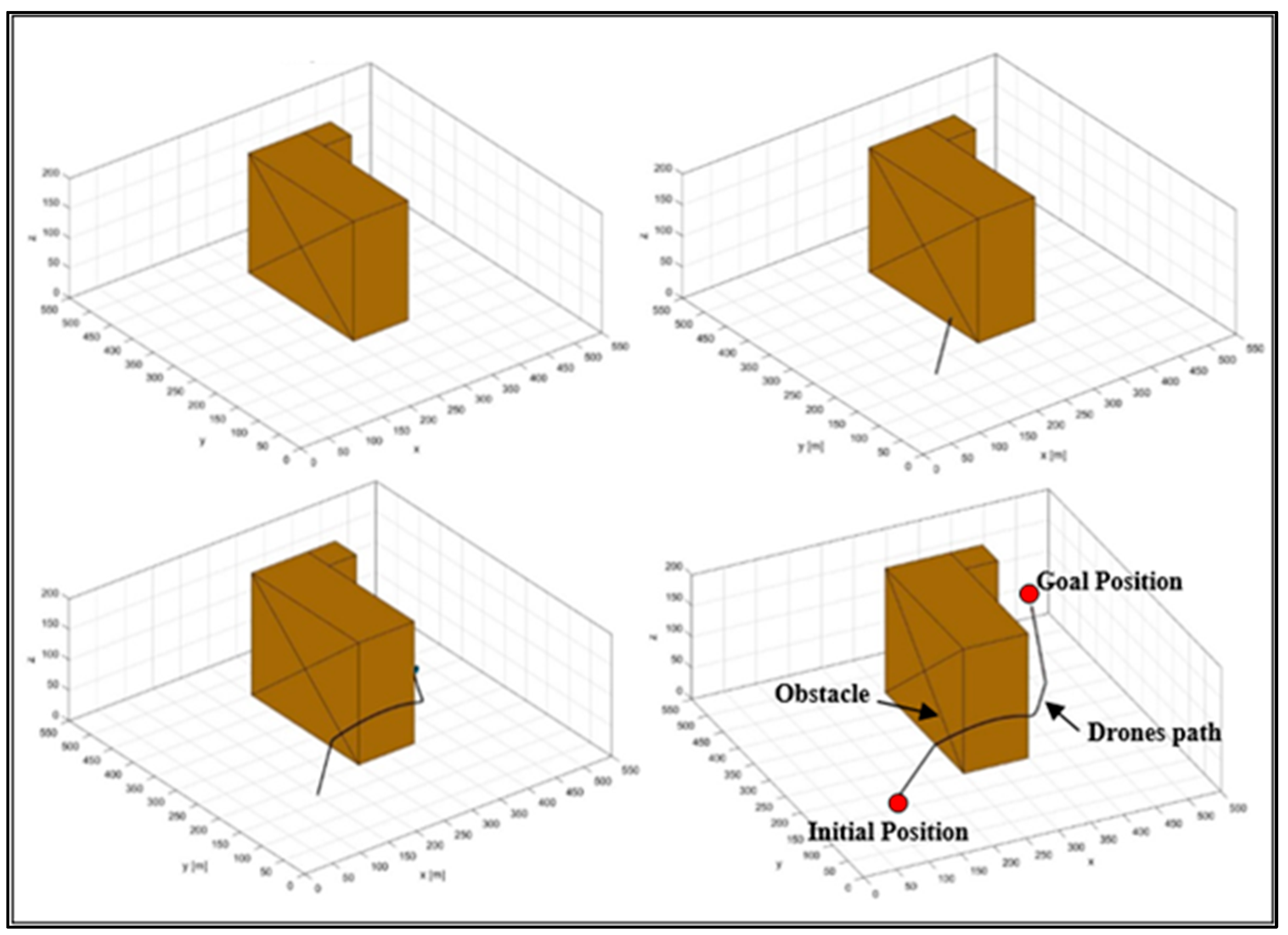
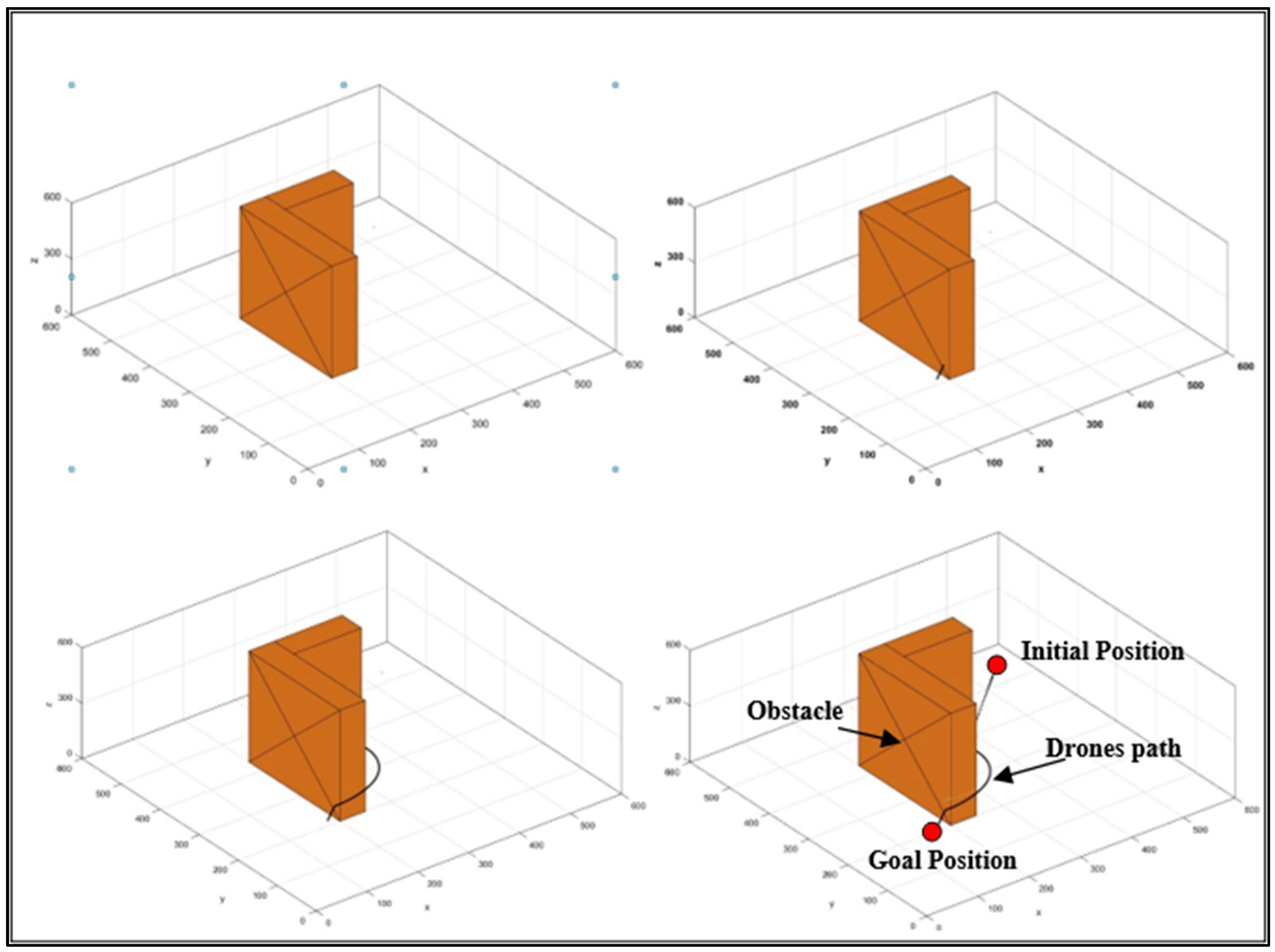
Over twenty trials with a maximum velocity of 0.2 m/s were carried out on the drone in both simulated and real-time scenarios for this study. The drone’s real-time navigation and its navigation in the 2D simulation environment is shown in
Figure 5,
Figure 6,
Figure 7 and
Figure 8. Scenario 1 involves comparing the virtual navigation of the drone in simulation (
Figure 6) with the real-time environment (
Figure 5). In Scenario 2,
Figure 7 and
Figure 8 are compared in obstacle-contained environments. The drone’s starting location, the goal position, the number of obstacles, and the obstacle’s position are all similar in the environments taken into consideration for the simulation analysis and the experimental setup. The goal of the analysis is to compare the path’s length and the amount of time needed for navigation when the drone plans its route from the starting point to the destination. It is evident from the results in
Table 4 and
Table 5 (Scenarios 1 and 2) that the path length and navigational time needed in simulation results are significantly shorter than in experiment results. Our primary goal is to minimize the percentage of the difference between path length and navigational time when comparing the outcomes of simulations and experiments. Based on the collected data, the deviation percentage in both cases is less than 5.0%, indicating that the suggested T3DRM-based controller is quite effective.
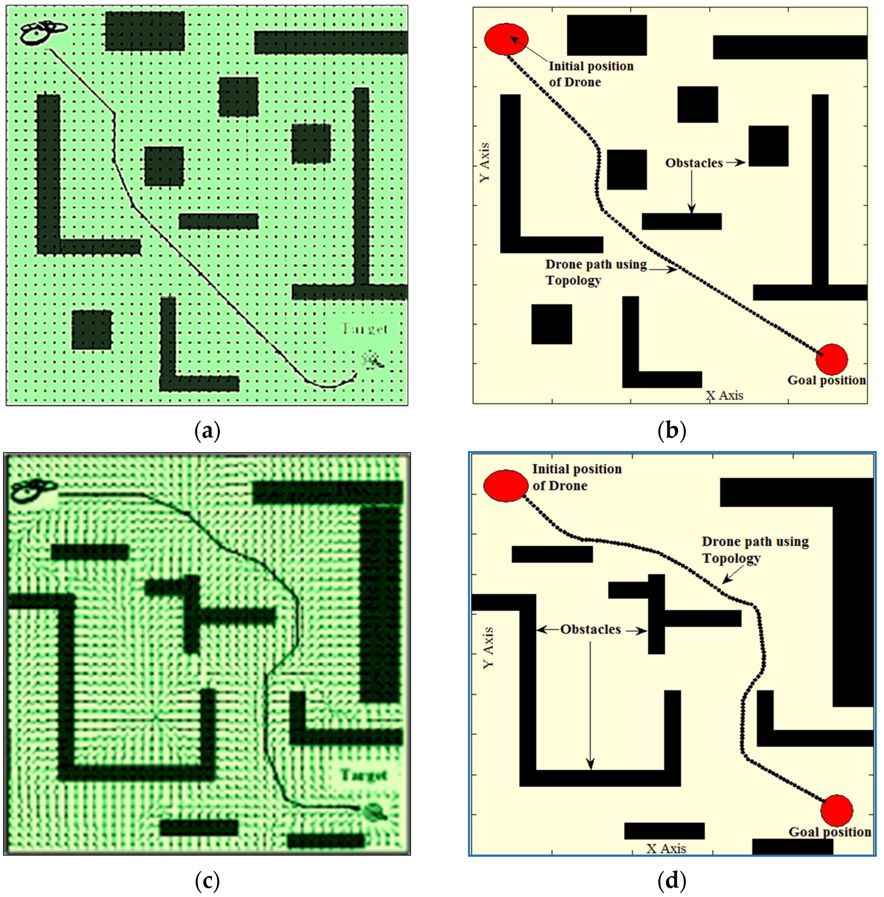
The methodology offered by other drone navigation researchers is compared with the suggested T3DRM-based strategy in Scenarios 3, 4, and 5. A potential field approach is employed in one such study [
35] to guide drones in indoor spaces, especially when they come across unknown objects.
Figure 9a,c show how the drone navigates using this technique. As seen in
Figure 9b,d, a fresh simulation setup is made with the same environmental parameters as those considered in the cited work to conduct a comparative analysis. This covers elements like the quantity, size, and locations of obstacles in addition to the drone’s starting and finishing places. Similarly, the proposed approach is also compared with Ant Colony Optimization (ACO) [
36] in a similar simulation environment that includes multiple obstacles (
Figure 9e,f). It is clear from the numerical results for Scenarios 3, 4, and 5 (
Table 6 and
Table 7) that using the T3DRM technique leads to notable gains. In Scenarios 3, 4, and 5, the T3DRM technique delivers path length reductions of up to 7.52%, 9.98%, and 2.0, respectively. Furthermore, using the T3DRM technique results in navigational time savings of 5.4%, 8.6%, and 7.04 in Scenarios 3, 4, and 5, respectively.

