
Colored 3D Path Extraction Based on Depth-RGB Sensor for Welding Robot Trajectory Generation

 ,
,  ,
,  ,
,  and
and
Abstract
:1. Introduction
2. Materials and Methods
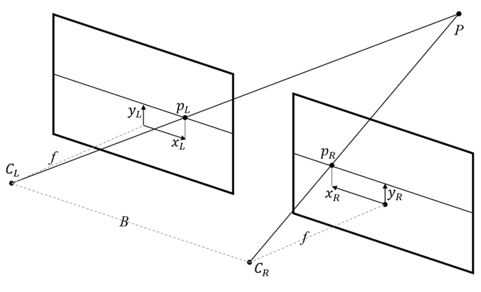
2.1. Stereo Vision
2.2. Structured Light
2.3. Point Cloud
2.4. Colored Point Cloud
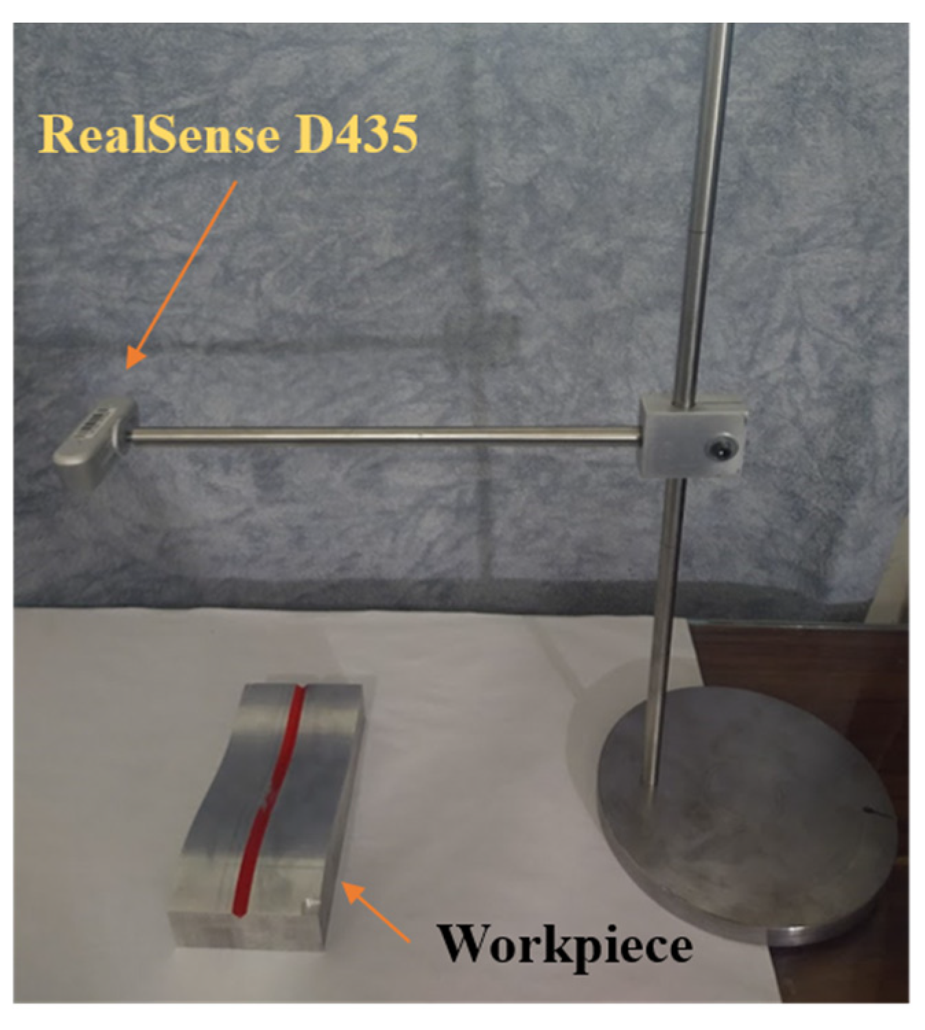
3. Experimental Setup
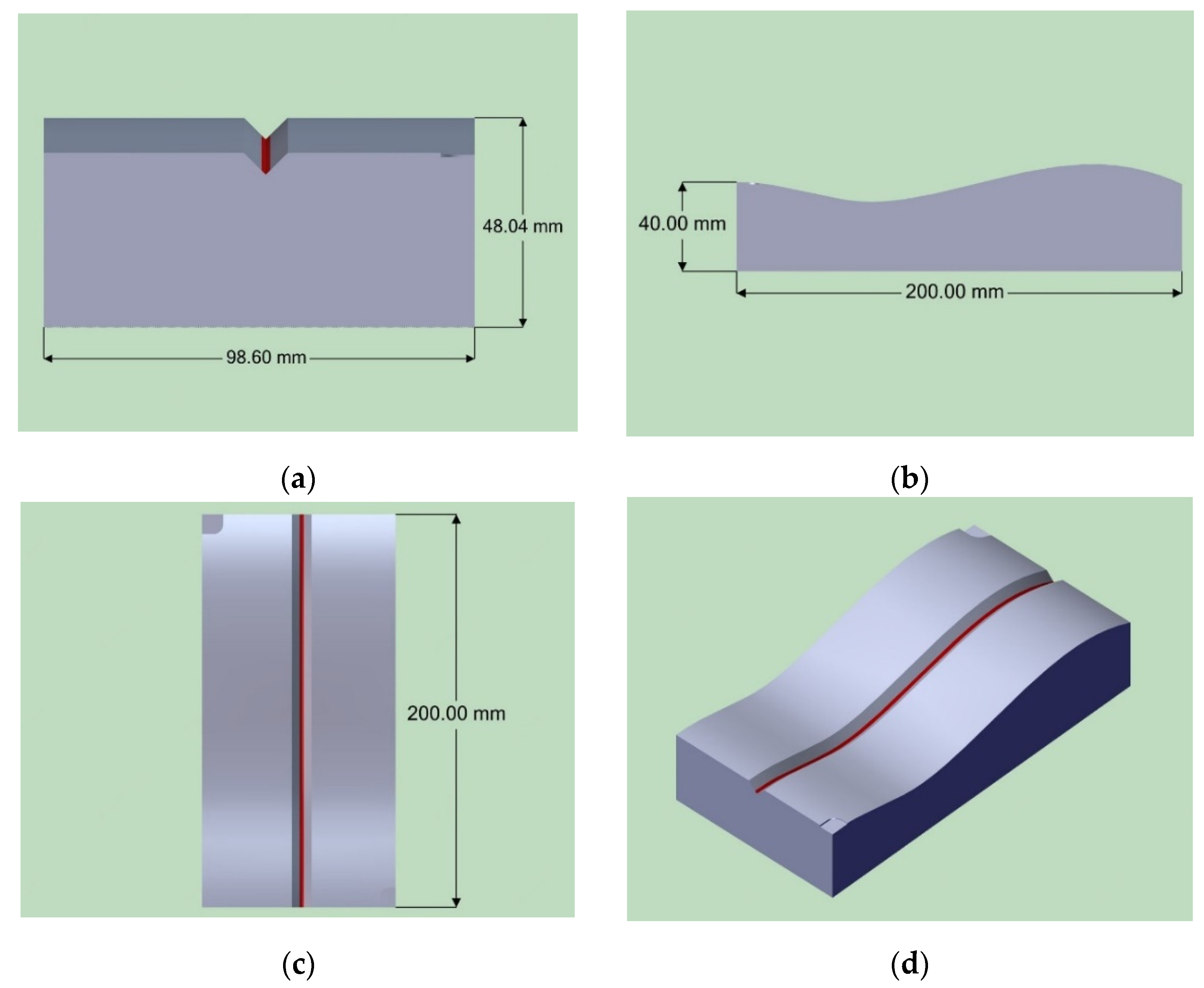
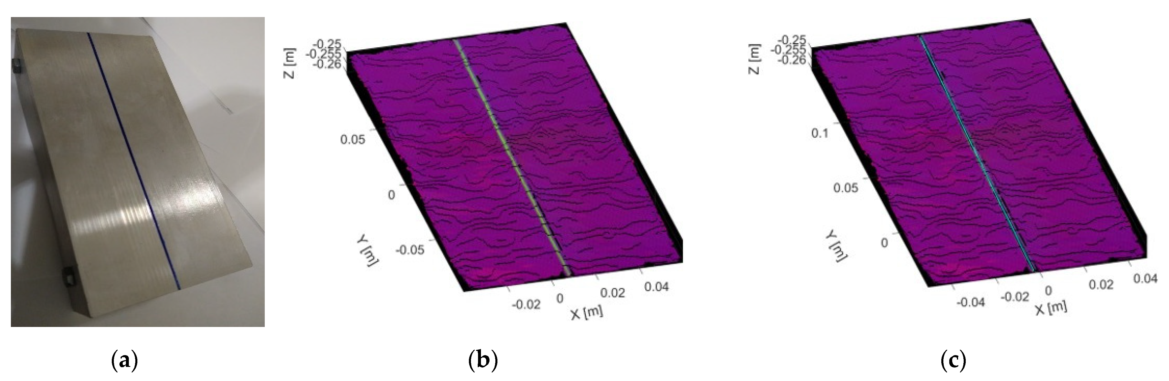
3.1. Test Sample
3.2. Trajectory Extraction Based on Stereo Vision System Embedding Color Data
3.3. 3D Reconstruction with RealSense D435 Sensor
4. Results
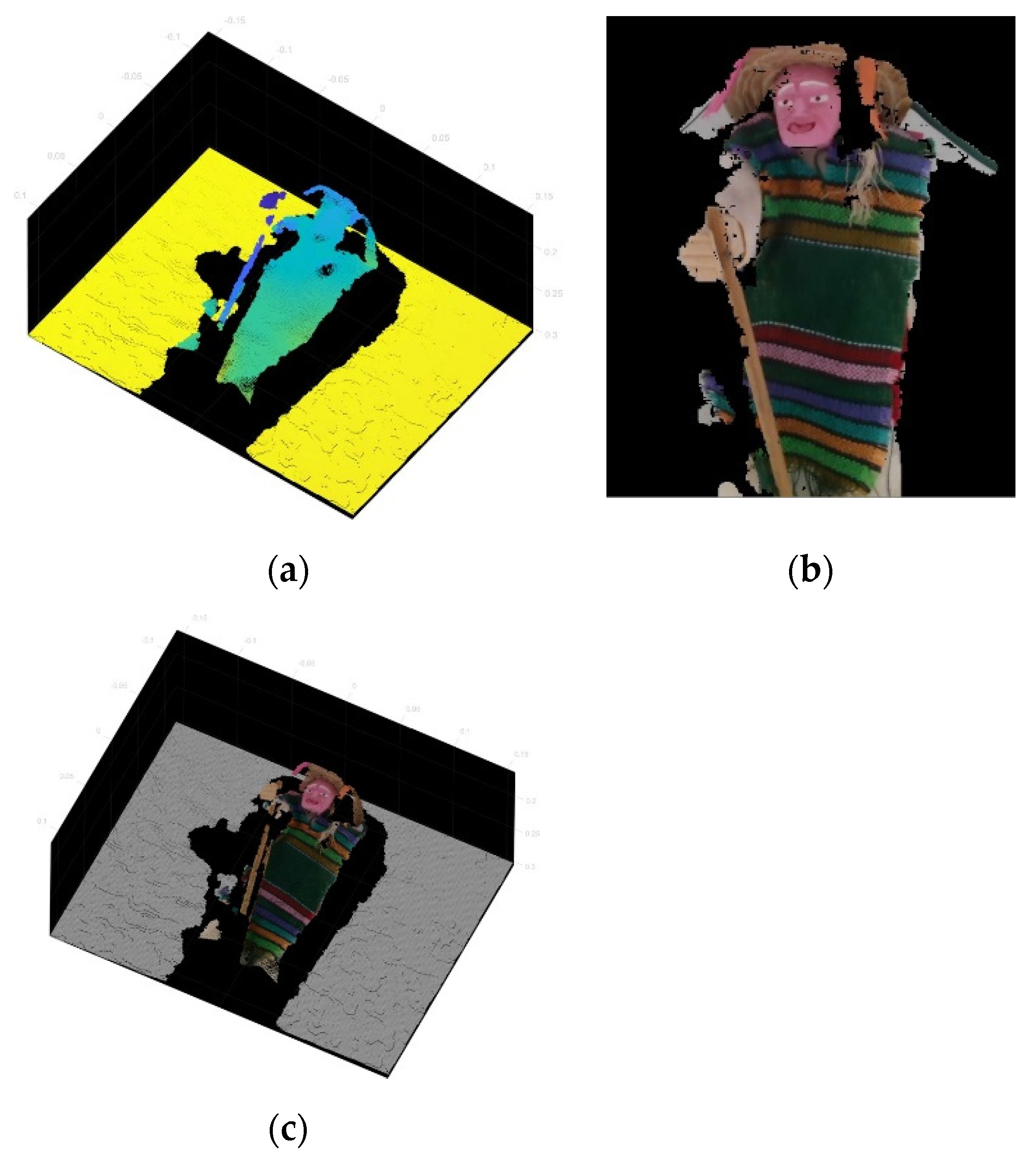
4.1. RealSense D435 3D Reconstruction Performance
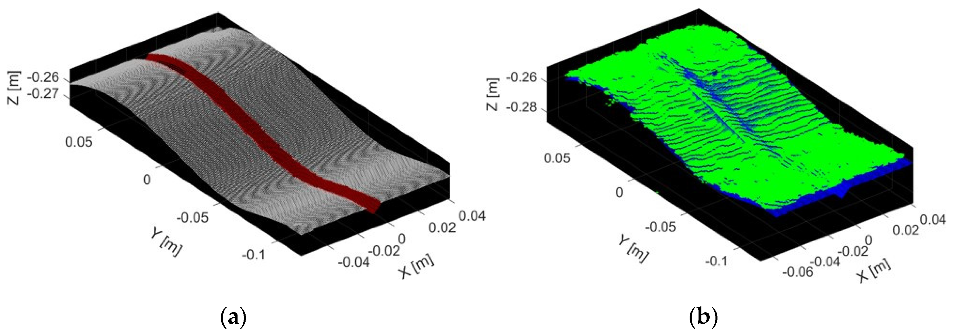
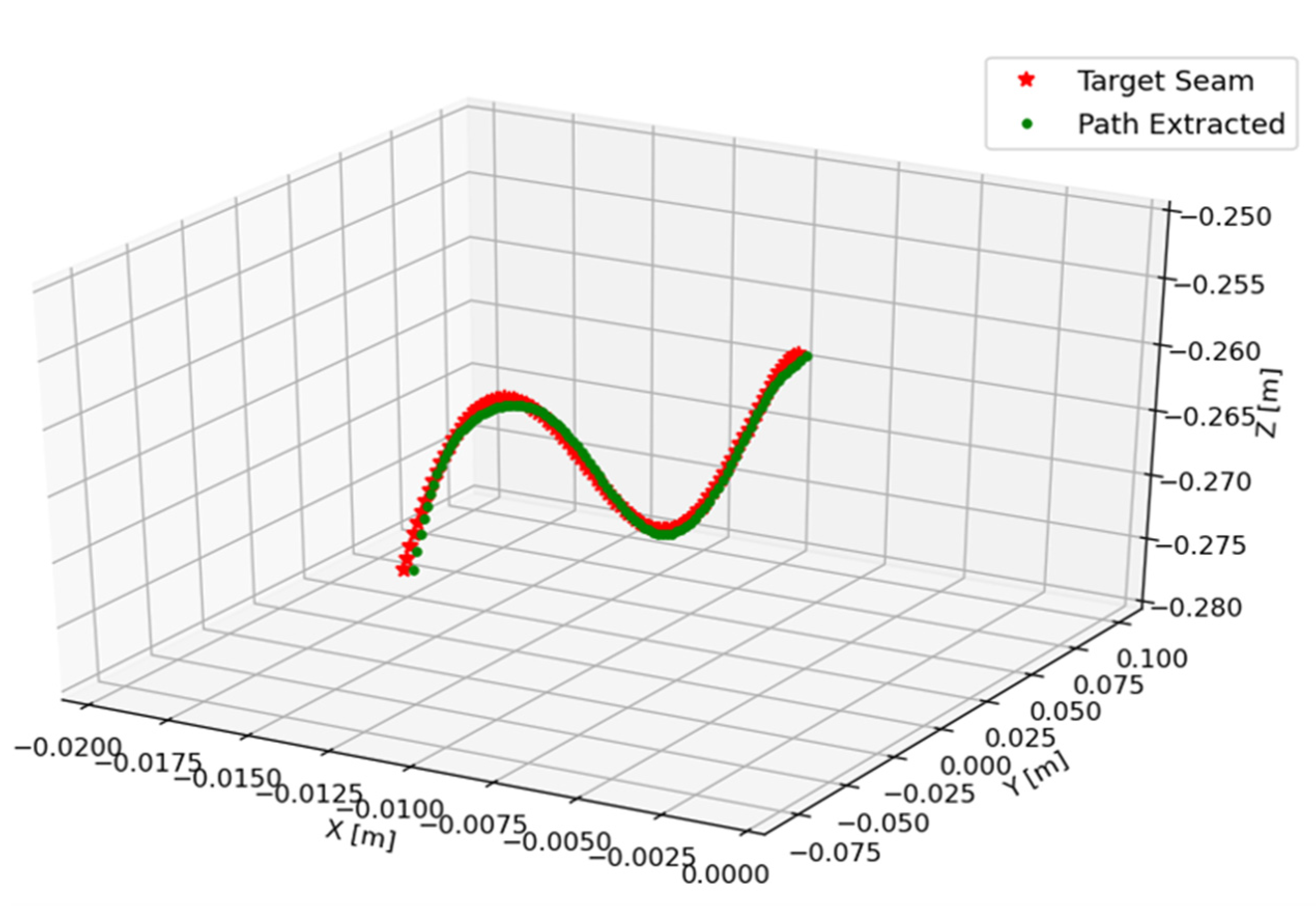
4.2. Trajectory Extraction of the Weld Bead by Colorimetry Point Cloud Segmentation
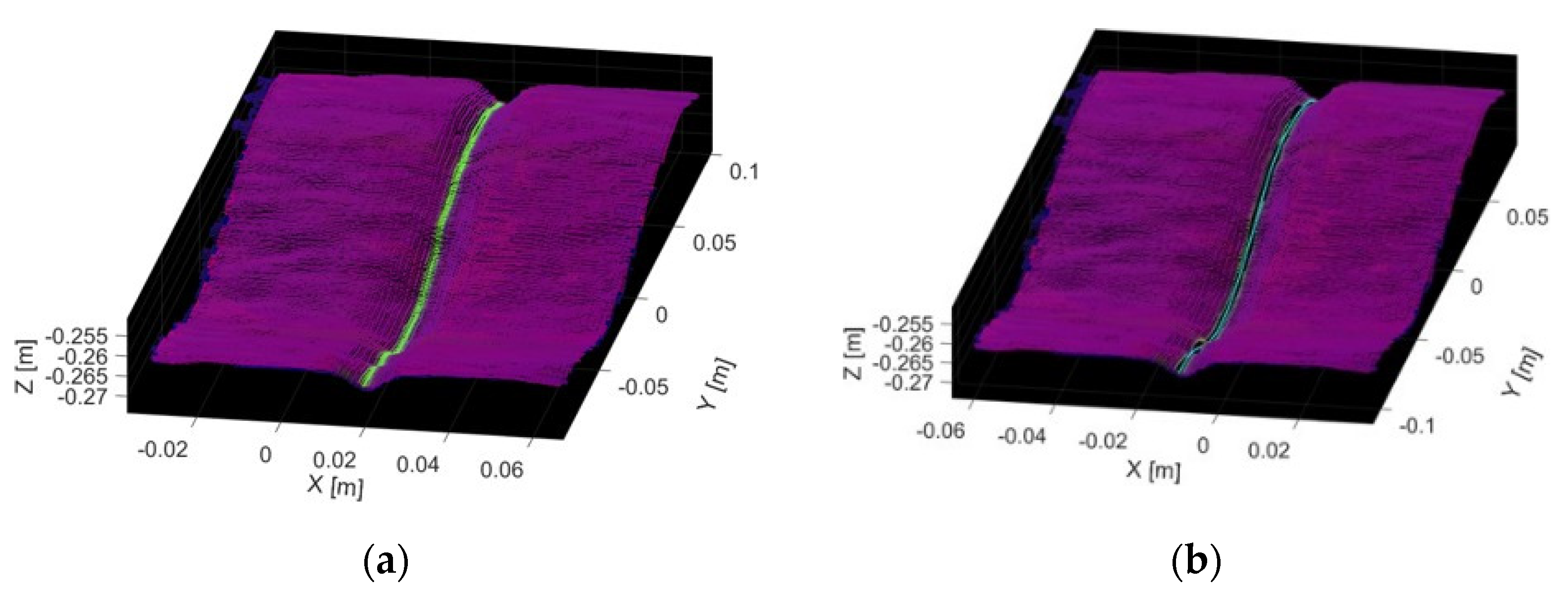
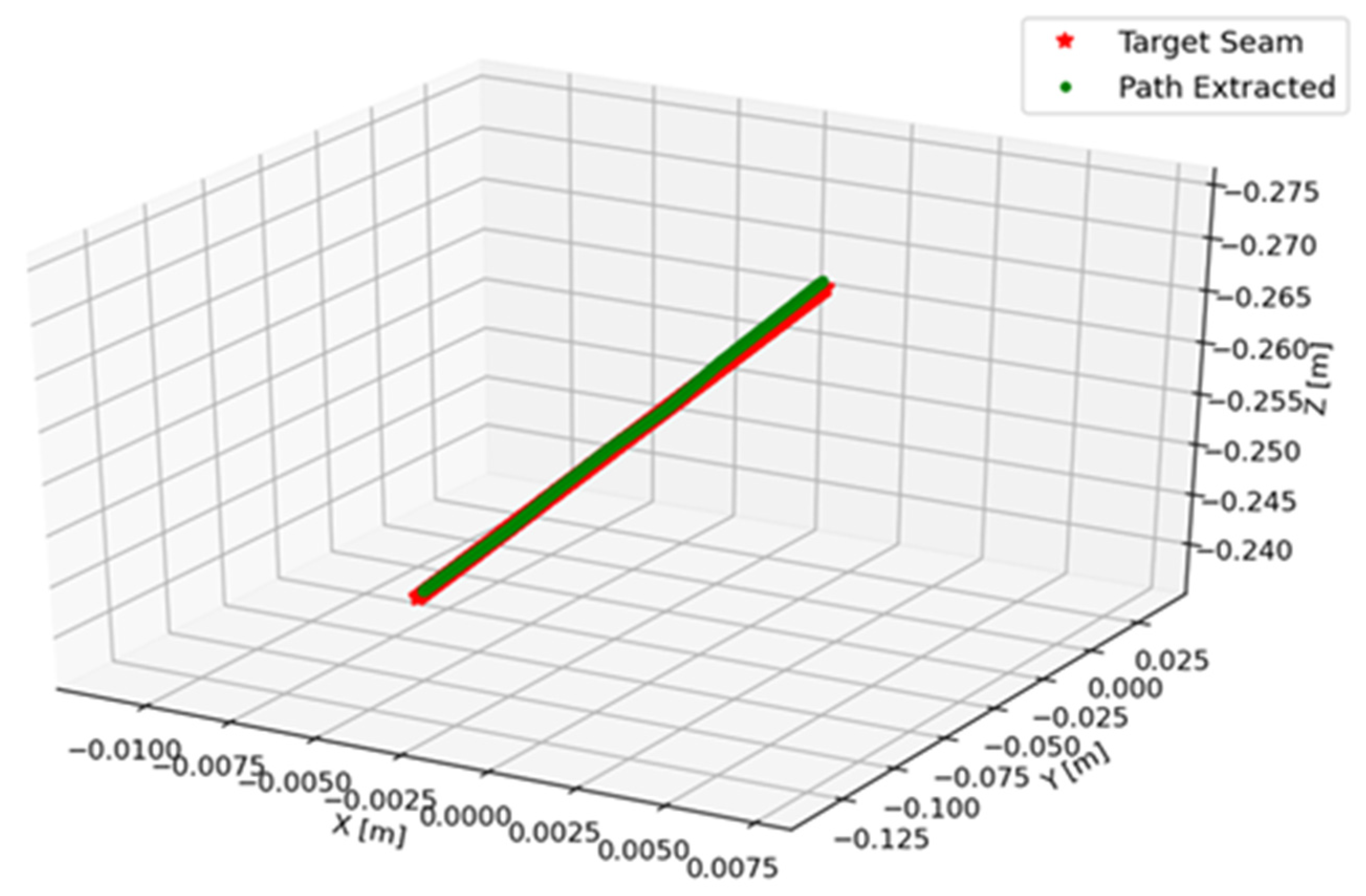
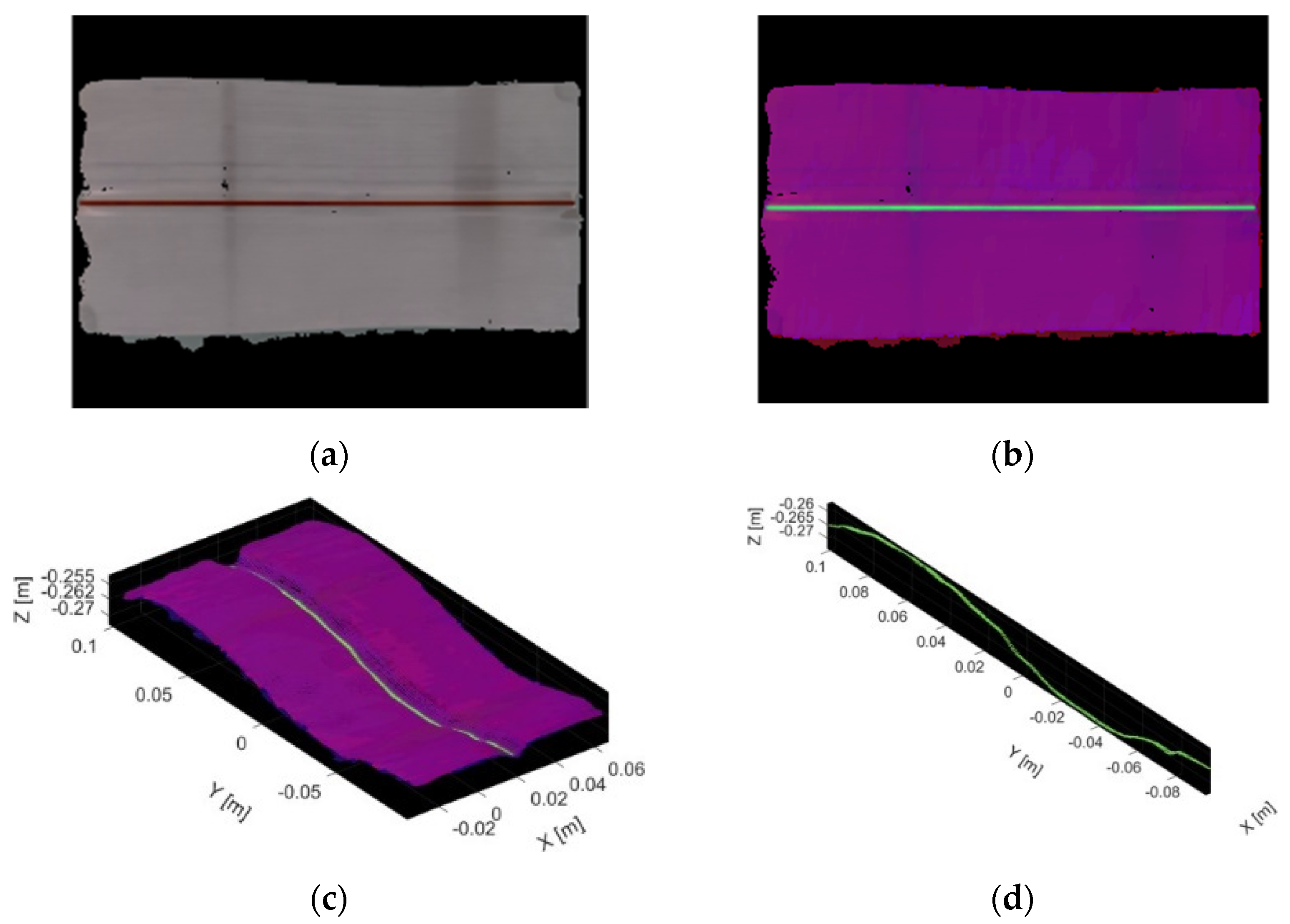
4.3. Testing Trajectory Extraction of a V-Type Butt Joint
4.4. Testing Trajectory Extraction of a Straight Butt Joint
5. Conclusions
- (1)
- A welding robot sensor based on stereo vision and RGB sensor was implemented in this paper that could finish the 3D color reconstruction task of welding workpiece, with a reconstruction standard deviation less than 1 mm, which is a parameter comparable to that shown by Carfagni [33] for similar devices.
- (2)
- In order to achieve quick and robust weld 3D path extraction, a color segmentation based on color point cloud reconstruction was performed, with thresholds in HSV color space and an interpolation of the segmented points. The trajectory extraction results show errors close to or below 1.1 mm for V-type butt joint and below 0.6 mm for a straight butt joint, comparable with other stereo vision studies; for example, Yang et al. [20] show that the measurement resolution is less than 0.7 mm for V-type butt joint, and in contrast, Zhou et al. [23] show a pose accuracy RMSE of 0.8 mm for a cylinder butt joint using a RealSense D415 sensor.
- (3)
- In addition to the above, the adaptability of the proposed trajectory extraction system, due to being a global capture system, shows results that encourage experimentation in V-type welding as one of the more studied in the literature, but also in other types of welding that would give a differential over most of the proposals found in the literature.
Author Contributions
Funding
Data Availability Statement
Acknowledgments
Conflicts of Interest
References
- Ogbemhe, J.; Mpofu, K. Towards achieving a fully intelligent robotic arc welding: A review. Ind. Robot Int. J. 2015, 42, 475–484. [Google Scholar] [CrossRef]
- Pan, Z.; Polden, J.; Larkin, N.; Van Duin, S.; Norrish, J. Recent progress on programming methods for Industrial Robots. Robot. Comput. Integr. Manuf. 2012, 28, 87–94. [Google Scholar] [CrossRef] [Green Version]
- Pérez, L.; Rodríguez, Í.; Rodríguez, N.; Usamentiaga, R.; García, D.F. Robot Guidance Using Machine Vision Techniques in Industrial Environments: A Comparative Review. Sensors 2016, 16, 335. [Google Scholar] [CrossRef]
- Lei, T.; Rong, Y.; Wang, H.; Huang, Y.; Li, M. A review of vision-aided robotic welding. Comput. Ind. 2020, 123, 103326. [Google Scholar] [CrossRef]
- Kiddee, P.; Fang, Z.; Tan, M. Visual recognition of the initial and end points of lap joint for welding robots. In 2014 IEEE International Conference on Information and Automation (ICIA); IEEE: Piscataway, NJ, USA, 2014. [Google Scholar] [CrossRef]
- Ye, Z.; Fang, G.; Chen, S.; Dinham, M. A robust algorithm for weld seam extraction based on prior knowledge of weld seam. Sens. Rev. 2013, 33, 125–133. [Google Scholar] [CrossRef]
- Yang, L.; Li, E.; Long, T.; Fan, J.; Mao, Y.; Fang, Z.; Liang, Z. A welding quality detection method for arc welding robot based on 3D reconstruction with SFS algorithm. Int. J. Adv. Manuf. Technol. 2017, 94, 1209–1220. [Google Scholar] [CrossRef]
- Villan, A.F.; Acevedo, R.G.; Alvarez, E.A.; Campos-Lopez, A.M.; Garcia-Martinez, D.F.; Fernandez, R.U.; Meana, M.J.; Sanchez, J.M.G. Low-cost system for weld tracking based on artificial vision. IEEE Trans. Ind. Appl. 2011, 47, 1159–1167. [Google Scholar] [CrossRef]
- Liu, F.Q.; Wang, Z.Y.; Ji, Y. Precise initial weld position identification of a fillet weld seam using laser vision technology. Int. J. Adv. Manuf. Technol. 2018, 99, 2059–2068. [Google Scholar] [CrossRef]
- Li, X.; Li, X.; Ge, S.S.; Khyam, M.O.; Luo, C. Automatic welding Seam tracking and identification. IEEE Trans. Ind. Electron. 2017, 64, 7261–7271. [Google Scholar] [CrossRef]
- Fan, J.; Jing, F.; Yang, L.; Teng, L.; Tan, M. A precise initial weld point guiding method of micro-gap weld based on structured light vision sensor. IEEE Sens. J. 2019, 19, 322–331. [Google Scholar] [CrossRef]
- Zeng, J.; Chang, B.; Du, D.; Wang, L.; Chang, S.; Peng, G.; Wang, W. A Weld Position Recognition Method Based on Directional and Structured Light Information Fusion in Multi-Layer/Multi-Pass Welding. Sensors 2018, 18, 129. [Google Scholar] [CrossRef] [PubMed] [Green Version]
- Guo, J.; Zhu, Z.; Sun, B.; Yu, Y. A novel multifunctional visual sensor based on combined laser structured lights and its anti-jamming detection algorithms. Weld. World 2018, 63, 313–322. [Google Scholar] [CrossRef]
- Kos, M.; Arko, E.; Kosler, H.; Jezeršek, M. Remote laser welding with in-line adaptive 3D seam tracking. Int. J. Adv. Manuf. Technol. 2019, 103, 4577–4586. [Google Scholar] [CrossRef] [Green Version]
- Zhang, K.; Yan, M.; Huang, T.; Zheng, J.; Li, Z. 3D reconstruction of complex spatial weld seam for autonomous welding by laser structured light scanning. J. Manuf. Process. 2019, 39, 200–207. [Google Scholar] [CrossRef]
- Chen, X.Z.; Chen, S.B. The autonomous detection and guiding of start welding position for arc welding robot. Ind. Robot Int. J. 2010, 37, 70–78. [Google Scholar] [CrossRef]
- Dinham, M.; Fang, G. Autonomous weld seam identification and localisation using eye-in-hand stereo vision for robotic arc welding. Robot. Comput. Integr. Manuf. 2013, 29, 288–301. [Google Scholar] [CrossRef]
- Ma, H.; Wei, S.; Lin, T.; Chen, S.; Li, L. Binocular vision system for both weld pool and root gap in robot welding process. Sens. Rev. 2010, 30, 116–123. [Google Scholar] [CrossRef]
- Xiao, R.; Xu, Y.; Hou, Z.; Chen, C.; Chen, S. An adaptive feature extraction algorithm for multiple typical seam tracking based on vision sensor in robotic arc welding. Sens. Actuators A Phys. 2019, 297, 111533. [Google Scholar] [CrossRef]
- Yang, L.; Li, E.; Long, T.; Fan, J.; Liang, Z. A novel 3-d path extraction method for arc welding robot based on stereo structured light sensor. IEEE Sens. J. 2019, 19, 763–773. [Google Scholar] [CrossRef]
- Yang, L.; Liu, Y.; Peng, J.; Liang, Z. A novel system for off-line 3D seam extraction and path planning based on point cloud segmentation for arc welding robot. Robot. Comput. Integr. Manuf. 2020, 64, 101929. [Google Scholar] [CrossRef]
- Maiolino, P.; Woolley, R.; Branson, D.; Benardos, P.; Popov, A.; Ratchev, S. Flexible robot sealant dispensing cell using RGB-D sensor and off-line programming. Robot. Comput. Integr. Manuf. 2017, 48, 188–195. [Google Scholar] [CrossRef] [Green Version]
- Zhou, P.; Peng, R.; Xu, M.; Wu, V.; Navarro-Alarcon, D. Path planning with automatic seam extraction over point cloud models for robotic arc welding. IEEE Robot. Autom. Lett. 2021, 6, 5002–5009. [Google Scholar] [CrossRef]
- Tippetts, B.; Lee, D.J.; Lillywhite, K.; Archibald, J. Review of stereo vision algorithms and their suitability for resource-limited systems. J. Real-Time Image Process. 2013, 11, 5–25. [Google Scholar] [CrossRef]
- Ke, F.; Liu, H.; Zhao, D.; Sun, G.; Xu, W.; Feng, W. A high precision image registration method for measurement based on the stereo camera system. Optik 2020, 204, 164186. [Google Scholar] [CrossRef]
- Zhang, S. High-speed 3D shape measurement with structured light methods: A review. Opt. Lasers Eng. 2018, 106, 119–131. [Google Scholar] [CrossRef]
- Geng, J. Structured-light 3D surface imaging: A tutorial. Adv. Opt. Photonics 2011, 3, 128. [Google Scholar] [CrossRef]
- Bi, Z.M.; Wang, L. Advances in 3D data acquisition and processing for industrial applications. Robot. Comput. Integr. Manuf. 2010, 26, 403–413. [Google Scholar] [CrossRef]
- Laganiere, R.; Gilbert, S.; Roth, G. Robust object pose estimation from feature-based stereo. IEEE Trans. Instrum. Meas. 2006, 55, 1270–1280. [Google Scholar] [CrossRef]
- Park, J.; Zhou, Q.-Y.; Koltun, V. Colored point cloud registration revisited. In 2017 IEEE International Conference on Computer Vision (ICCV); IEEE: Piscataway, NJ, USA, 2017. [Google Scholar] [CrossRef]
- Huang, X.; Zhang, J.; Wu, Q.; Fan, L.; Yuan, C. A coarse-to-fine algorithm for matching and registration in 3d CROSS-SOURCE point clouds. IEEE Trans. Circuits Syst. Video Technol. 2018, 28, 2965–2977. [Google Scholar] [CrossRef] [Green Version]
- Grunnet-Jepsen, A.; Tong, D. Depth Post-Processing FOR Intel® REALSENSE™ Depth Camera D400 Series. Available online: https://dev.intelrealsense.com/docs/depth-post-processing (accessed on 12 September 2021).
- Carfagni, M.; Furferi, R.; Governi, L.; Santarelli, C.; Servi, M.; Uccheddu, F.; Volpe, Y. Metrological and Critical Characterization of the Intel D415 Stereo Depth Camera. Sensors 2019, 19, 489. [Google Scholar] [CrossRef] [Green Version]


| Tool Path | Tool- | Vc (m/min) | RPM | F (mm) |
|---|---|---|---|---|
| Facing | Facer 2.5” | 650 | 3500 | 300 |
| Pocketing | Flat 0.25” | 120 | 6000 | 7 |
| Drilling | Drill 0.203” | 50 | 3048 | 6 |
| Tangent to curve | Flat 1.0” | 350 | 4500 | 40 |
| Wall machining | Flat 0.5” | 200 | 5000 | 30 |
| Z level | Flat 0.437” | 250 | 5500 | 47 |
| Z finishing | Ball 0.25” | 100 | 6000 | 32 |
| Average | Standard Deviation | |
|---|---|---|
| Test 1 | 0.704 mm | 0.378 mm |
| Test 2 | 1.053 mm | 0.623 mm |
| Test 3 | 1.284 mm | 0.738 mm |
| Hue | Saturation | |
|---|---|---|
| Red | 160–180 | 100–255 |
| Green | 30–50 | 100–255 |
| Blue | 110–120 | 50–255 |
| X | Y | Z | |
|---|---|---|---|
| Test 1 | 0.063 mm | 0. 184 mm | 0.952 mm |
| Test 2 | 0.046 mm | 0.195 mm | 1.059 mm |
| Test 3 | 0.010 mm | 0.145 mm | 0.739 mm |
| Average | Standard Deviation | |
|---|---|---|
| Test 1 | 0.70 mm | 0.30 mm |
| Test 2 | 0.80 mm | 0.30 mm |
| Test 3 | 0.80 mm | 0.30 mm |
| X | Y | Z | Average | Standard Deviation | |
|---|---|---|---|---|---|
| Test 1 | 0.142 mm | 0.075 mm | 0.683 mm | 0.60 mm | 0.20 mm |
| Test 2 | 0.124 mm | 0.072 mm | 0.530 mm | 0.50 mm | 0.20 mm |
| Test 3 | 0.180 mm | 0.069 mm | 0.494 mm | 0.50 mm | 0.20 mm |
Publisher’s Note: MDPI stays neutral with regard to jurisdictional claims in published maps and institutional affiliations. |
© 2021 by the authors. Licensee MDPI, Basel, Switzerland. This article is an open access article distributed under the terms and conditions of the Creative Commons Attribution (CC BY) license (https://creativecommons.org/licenses/by/4.0/).
Share and Cite
Gómez-Espinosa, A.; Rodríguez-Suárez, J.B.; Cuan-Urquizo, E.; Cabello, J.A.E.; Swenson, R.L. Colored 3D Path Extraction Based on Depth-RGB Sensor for Welding Robot Trajectory Generation. Automation 2021, 2, 252-265. https://doi.org/10.3390/automation2040016
Gómez-Espinosa A, Rodríguez-Suárez JB, Cuan-Urquizo E, Cabello JAE, Swenson RL. Colored 3D Path Extraction Based on Depth-RGB Sensor for Welding Robot Trajectory Generation. Automation. 2021; 2(4):252-265. https://doi.org/10.3390/automation2040016
Chicago/Turabian StyleGómez-Espinosa, Alfonso, Jesús B. Rodríguez-Suárez, Enrique Cuan-Urquizo, Jesús Arturo Escobedo Cabello, and Rick L. Swenson. 2021. "Colored 3D Path Extraction Based on Depth-RGB Sensor for Welding Robot Trajectory Generation" Automation 2, no. 4: 252-265. https://doi.org/10.3390/automation2040016
APA StyleGómez-Espinosa, A., Rodríguez-Suárez, J. B., Cuan-Urquizo, E., Cabello, J. A. E., & Swenson, R. L. (2021). Colored 3D Path Extraction Based on Depth-RGB Sensor for Welding Robot Trajectory Generation. Automation, 2(4), 252-265. https://doi.org/10.3390/automation2040016